Analysis of Building Structures & Load Transfer Methods in Engineering
VerifiedAdded on 2023/06/14
|13
|2106
|249
Report
AI Summary
This report provides a detailed structural analysis of an industrial building and a multi-story building, examining their structural features, material choices, and load transfer mechanisms. The industrial building, a commercial garage located in Coopers Plains, Qld, features reinforced concrete foundations and a structural steel roofing system. The multi-story building, One One One Eagle Street in Brisbane, is a skyscraper office building with a network of column and beam connections and a stiff structural core. The report discusses how horizontal and vertical loads are accommodated in both buildings, with horizontal loads acting as flexural and shear forces and vertical loads being transmitted through gravity load paths. The analysis includes timber tension member and beam designs, considering permanent, construction, and wind actions, as well as bending, shear, and bearing strength. The report concludes with calculations and checks for deflection limits in timber beam design, adhering to AS 1720.1—2010 standards.
Structural Engineering
1
STRUCTURAL ENGINEERING
By [Name]
Course
Professor’s Name
Institution
Location of Institution
Date
1
STRUCTURAL ENGINEERING
By [Name]
Course
Professor’s Name
Institution
Location of Institution
Date
Paraphrase This Document
Need a fresh take? Get an instant paraphrase of this document with our AI Paraphraser
Structural Engineering
2
Question1a
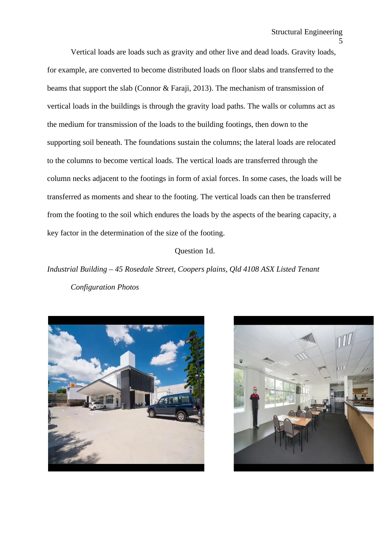
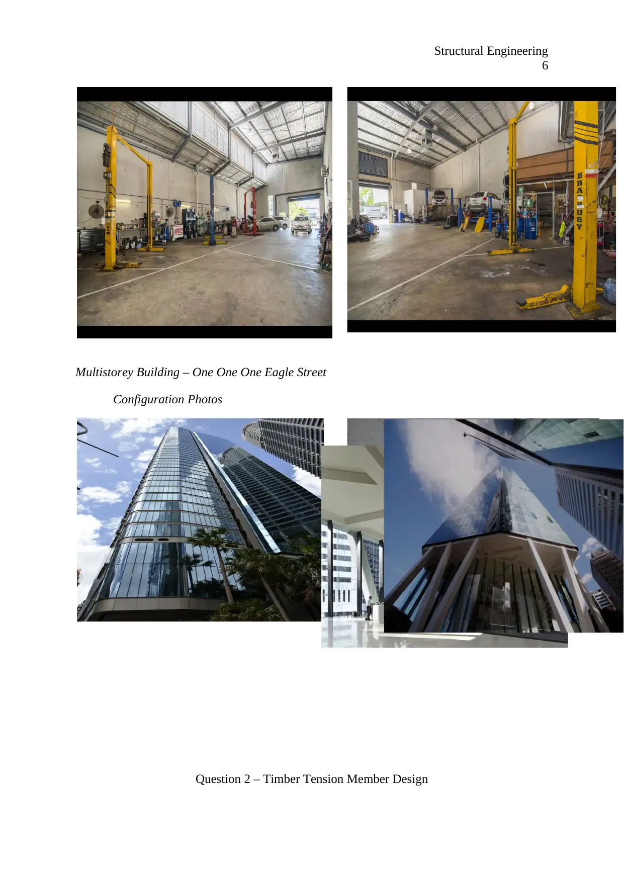
Industrial Building – 45 Rosedale Street, Coopers plains, Qld 4108 ASX Listed Tenant
Use of the Building
The industrial building I visited is a modern commercial industrial building that is
fully leased ASX listed tenant. The building is strategically located on 45 Rosedale Street,
Coopers Plains, Qld 4108 and adjacent to the Coopers Plains trains station. This is a
commercial building that can be primarily used as a garage for all types and sizes of motor
vehicles. The facility is portioned such that it has the garage area, and also office area. There
is also space for conferences, or meetings – board rooms.
Structural Features
Structural features of the building include reinforced concrete pad foundations with
isolated footing that are associated with concrete blinding, grade beams and exterior concrete
slab. Framing systems for roofs with designed structural steel i.e. for roof trusses. The
building is also decked with a composite concrete steel system and structurally designed
beam and columns connection systems. Other structural features of the building include wood
trusses, I-joists, floor trusses in some areas and engineered beams, columns and headers.
Multistorey Building – One One One Eagle Street
Use of the Building
The One One One Eagle street is a multistorey building at Brisbane city centre, 111
Eagle Street. The building is primarily used as an office. It is basically a commercial building
that comprises of many units that are used to serve staffs working in various organizations
and personal offices. The higher levels basically serve as offices, while lower levels have
other utilities such as restaurants, parking space, waiting areas etc. It is basically allocated for
multiple functions – it is a multi-use building.
Structural Features
Structural Engineering
3
The multistorey building is a 194.7 metre skyscraper office building with 54 floors
that include 44 levels of premium office space and a 115 parking space car park. The basic
structural features of the building include a network column and beam connections within the
structural skeleton, Cantilever slabs utelising internal core and external propped columns,
Bracing systems / braced frame structures, shear walls stiff structural core structures for lifts
and stairs, and composite truss systems.
Question 1b
Industrial Building – Choice of Structural Material
The building under consideration is basically used as a workshop. The building has a
large and clear space unobstructed by columns, with adequate headroom to allow use of
overhead travelling cranes. The choice of structural material used had to accommodate the
structural function of the building. The floors are designed with high strength concrete slabs
sufficient for resistance to impact, high temperatures, abrasion and shear depending on
activities carried out (Askeland & Wright, 2015).
Roofing system has been done using structural steel, with sheeting, purlin and
supporting seasoned timber roof trusses. The choice of structural material for roofing system
is done due to their insulating value, acoustical properties, and weight (Kumar & Kumar,
2018). Columns, beams and other structural members are made of steel and reinforced
concrete designed as per the buildings drift ratio to maintain high stability and structural
integrity (American Society of Civile Engineers, 2013).
Multi-Storey Building – Choice of Structural Material
Specific design types and material chosen for the building are as per office standards
in building and construction codes. Roofing and wall material are light weight to take care of
gravity forces and seismic forces. Structural steel of specified standards is selected for evaded
members, foundations, girts and wall bracing, all dependent on the type of wall used.
⊘ This is a preview!⊘
Do you want full access?
Subscribe today to unlock all pages.

Trusted by 1+ million students worldwide
Structural Engineering
4
Standard bay sizes of 30 ft x 30 ft to 40 ft x 40 ft are used in the greater structural part
of the building. The bay sizes are selected to specific standards to take care of the gravity
loads.
All material used in the construction of the building including steel, concrete, timber
etc are low weight , though not all of them. The material selection done and used for the
building improves resilience, facilitates temporary load conditions, permits deliberate
overdesign, and allows for fire protection. Some material is heavier to increase surface are to
volume ratio, thus saving both material and cost (Ward-Harvey, 2009).
Question 1c.
Horizontal and Vertical Loads
Generally,, the buildings are designed with strength and stiffness sufficient enough to
offers resistance to both horizontal loads and vertical loads that might result from the
structure itself, cracking or overturning of the bracing walls within the buildings.
Most horizontal loads are live loads. Typically, they could be wind loads,
earthquakes, earth pressures against retaining walls, and earth pressures against the basement
walls. The intensity of the horizontal loads in the building considered are varied depending
on the location, structural material, their heights and shapes. The buildings are built in shapes
that accommodate with loads. The mechanism of transfer of horizontal loads in both
buildings is by the structural members of the buildings. Structural elements shifts the loads to
other elements and finally to the footing through numerous forms. The horizontal loads act as
flexural forces because of moments, and shear forces in shear walls and core walls (Gupta &
Moss, 1993). Transmission to the footings begins from the slabs that support the live loads.
The loads are then transferred from the slabs to the beams, either in one way or two way
depending on the section of the building. The loads are then transferred to the footing through
the beams as vertical loads.
Paraphrase This Document
Need a fresh take? Get an instant paraphrase of this document with our AI Paraphraser
Structural Engineering
5
Vertical loads are loads such as gravity and other live and dead loads. Gravity loads,
for example, are converted to become distributed loads on floor slabs and transferred to the
beams that support the slab (Connor & Faraji, 2013). The mechanism of transmission of
vertical loads in the buildings is through the gravity load paths. The walls or columns act as
the medium for transmission of the loads to the building footings, then down to the
supporting soil beneath. The foundations sustain the columns; the lateral loads are relocated
to the columns to become vertical loads. The vertical loads are transferred through the
column necks adjacent to the footings in form of axial forces. In some cases, the loads will be
transferred as moments and shear to the footing. The vertical loads can then be transferred
from the footing to the soil which endures the loads by the aspects of the bearing capacity, a
key factor in the determination of the size of the footing.
Question 1d.
Industrial Building – 45 Rosedale Street, Coopers plains, Qld 4108 ASX Listed Tenant
Configuration Photos
Structural Engineering
6
Multistorey Building – One One One Eagle Street
Configuration Photos
Question 2 – Timber Tension Member Design
6
Multistorey Building – One One One Eagle Street
Configuration Photos
Question 2 – Timber Tension Member Design
⊘ This is a preview!⊘
Do you want full access?
Subscribe today to unlock all pages.

Trusted by 1+ million students worldwide
Structural Engineering
7
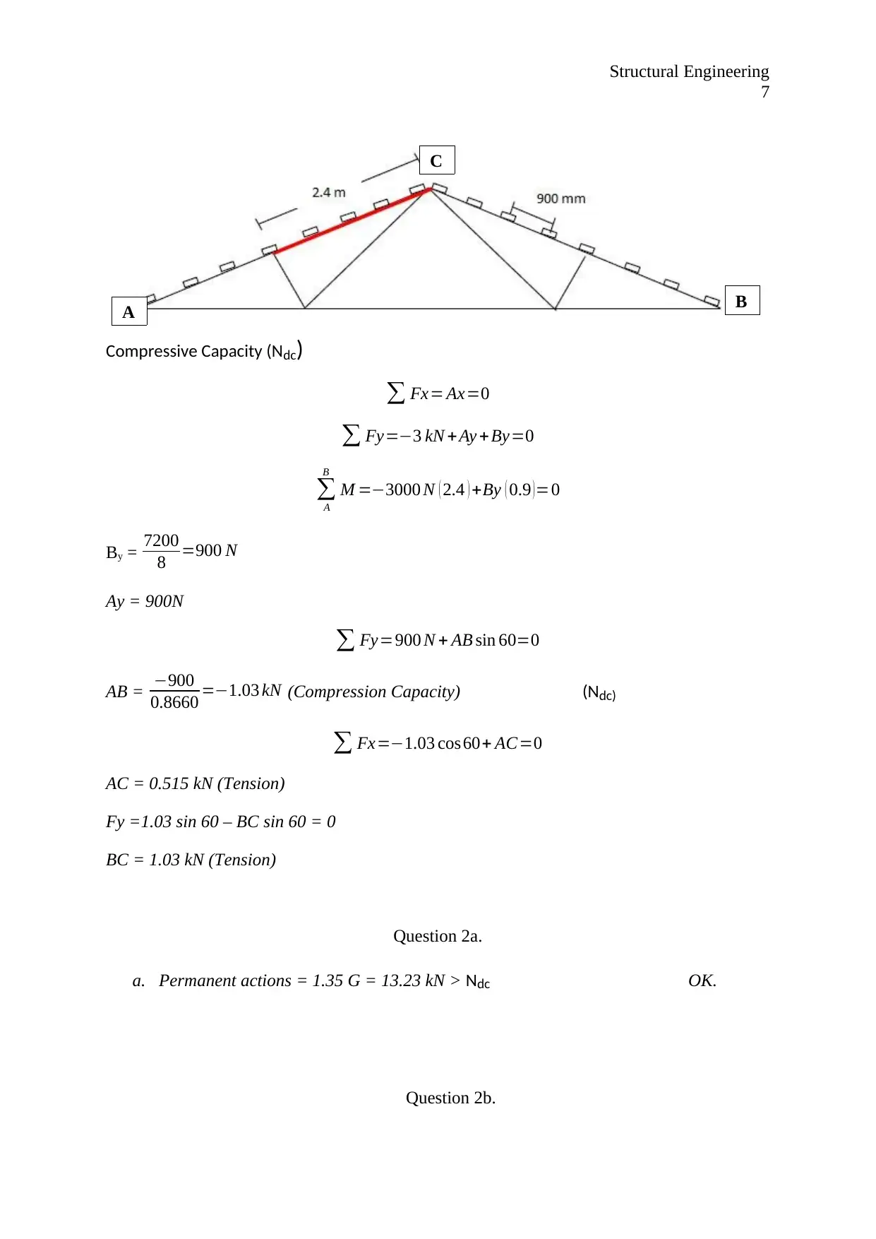
Compressive Capacity (Ndc)
∑ Fx= Ax=0
∑ Fy=−3 kN +Ay +By=0
∑
A
B
M =−3000 N ( 2.4 ) +By ( 0.9 ) =0
By = 7200
8 =900 N
Ay = 900N
∑ Fy=900 N + AB sin 60=0
AB = −900
0.8660 =−1.03 kN (Compression Capacity) (Ndc)
∑ Fx=−1.03 cos60+ AC=0
AC = 0.515 kN (Tension)
Fy =1.03 sin 60 – BC sin 60 = 0
BC = 1.03 kN (Tension)
Question 2a.
a. Permanent actions = 1.35 G = 13.23 kN > Ndc OK.
Question 2b.
A B
C
Paraphrase This Document
Need a fresh take? Get an instant paraphrase of this document with our AI Paraphraser
Structural Engineering
8
b. 5 day loading (construction loading) 1.2 G + 1.5 Q =16.26 kN > Ndc OK.
Question 2c.
c. Ultimate wind actions (downwards) 1.2 G + Wu = 26.76 > Ndc OK.
8
b. 5 day loading (construction loading) 1.2 G + 1.5 Q =16.26 kN > Ndc OK.
Question 2c.
c. Ultimate wind actions (downwards) 1.2 G + Wu = 26.76 > Ndc OK.
Structural Engineering
9
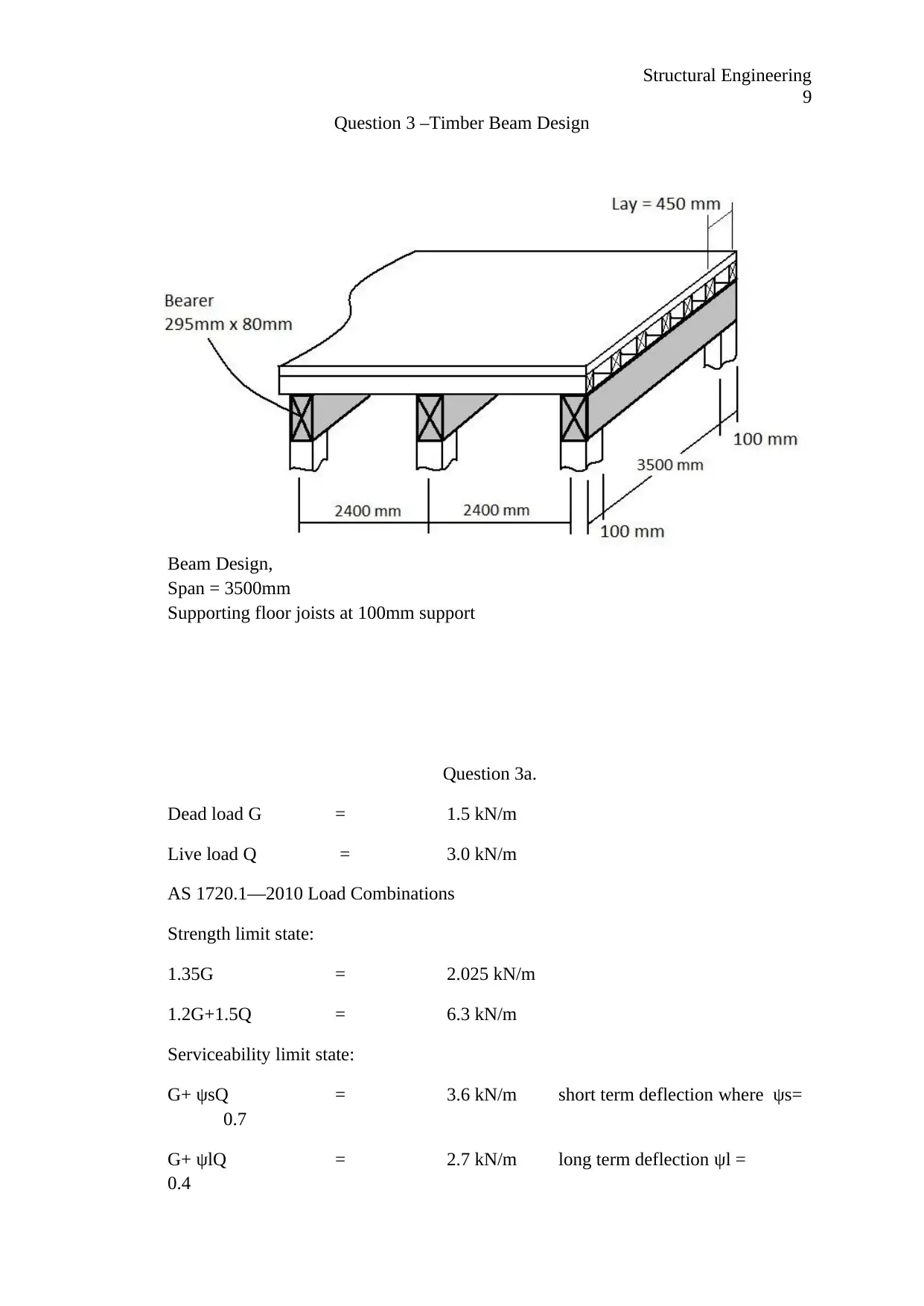
Question 3 –Timber Beam Design
Beam Design,
Span = 3500mm
Supporting floor joists at 100mm support
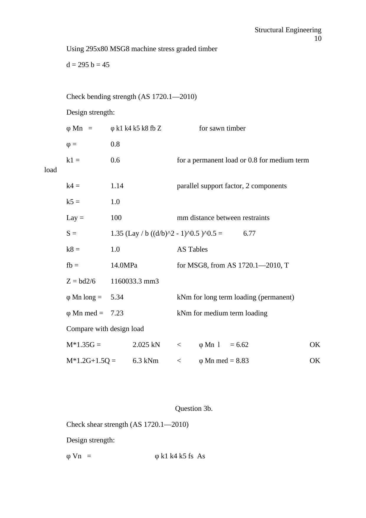
Question 3a.
Dead load G = 1.5 kN/m
Live load Q = 3.0 kN/m
AS 1720.1—2010 Load Combinations
Strength limit state:
1.35G = 2.025 kN/m
1.2G+1.5Q = 6.3 kN/m
Serviceability limit state:
G+ ψsQ = 3.6 kN/m short term deflection where ψs=
0.7
G+ ψlQ = 2.7 kN/m long term deflection ψl =
0.4
⊘ This is a preview!⊘
Do you want full access?
Subscribe today to unlock all pages.

Trusted by 1+ million students worldwide
Structural Engineering
10
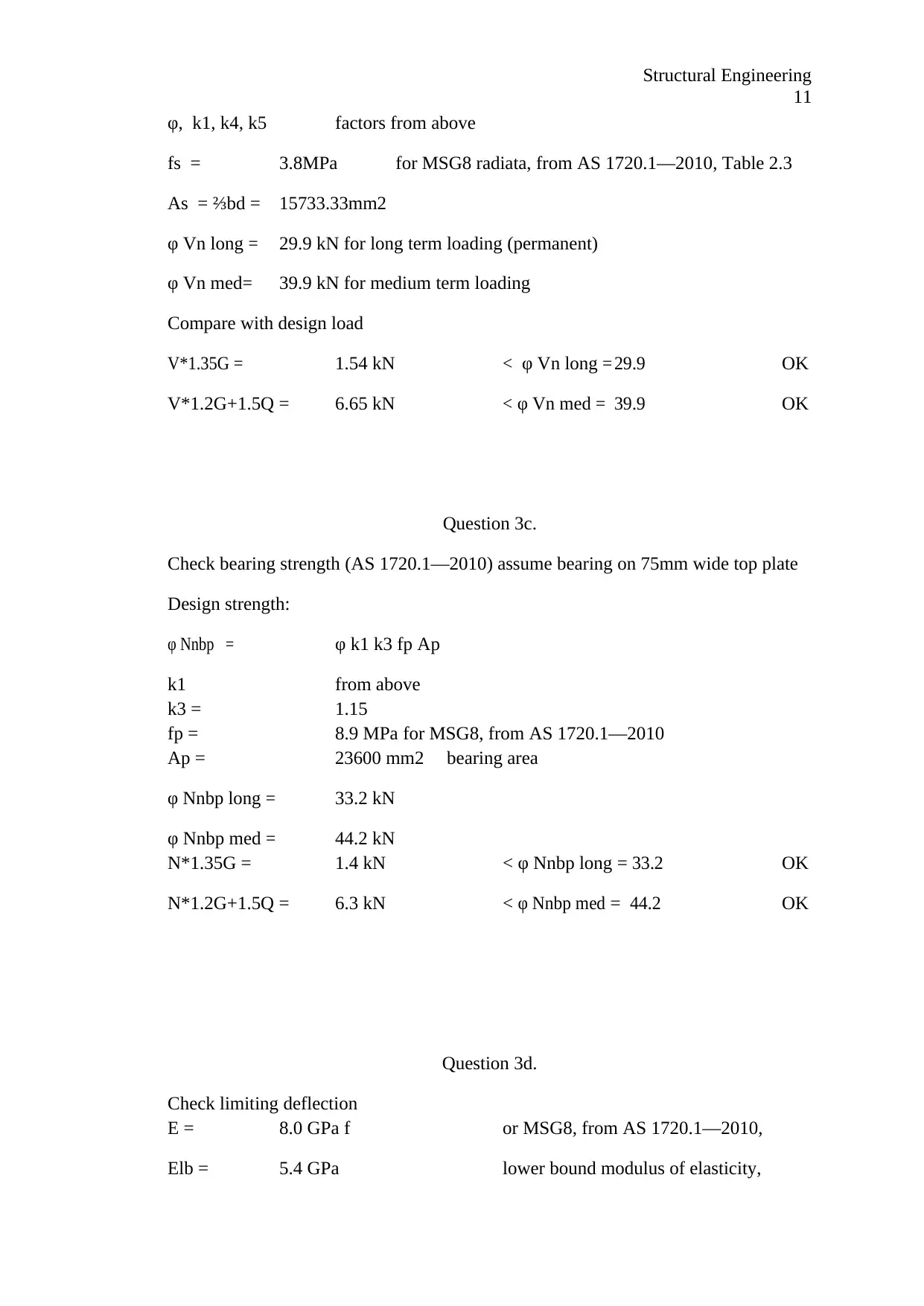
Using 295x80 MSG8 machine stress graded timber
d = 295 b = 45
Check bending strength (AS 1720.1—2010)
Design strength:
φ Mn = φ k1 k4 k5 k8 fb Z for sawn timber
φ = 0.8
k1 = 0.6 for a permanent load or 0.8 for medium term
load
k4 = 1.14 parallel support factor, 2 components
k5 = 1.0
Lay = 100 mm distance between restraints
S = 1.35 (Lay / b ((d/b)^2 - 1)^0.5 )^0.5 = 6.77
k8 = 1.0 AS Tables
fb = 14.0MPa for MSG8, from AS 1720.1—2010, T
Z = bd2/6 1160033.3 mm3
φ Mn long = 5.34 kNm for long term loading (permanent)
φ Mn med = 7.23 kNm for medium term loading
Compare with design load
M*1.35G = 2.025 kN < φ Mn l = 6.62 OK
M*1.2G+1.5Q = 6.3 kNm < φ Mn med = 8.83 OK
Question 3b.
Check shear strength (AS 1720.1—2010)
Design strength:
φ Vn = φ k1 k4 k5 fs As
Paraphrase This Document
Need a fresh take? Get an instant paraphrase of this document with our AI Paraphraser
Structural Engineering
11
φ, k1, k4, k5 factors from above
fs = 3.8MPa for MSG8 radiata, from AS 1720.1—2010, Table 2.3
As = ⅔bd = 15733.33mm2
φ Vn long = 29.9 kN for long term loading (permanent)
φ Vn med = 39.9 kN for medium term loading
Compare with design load
V*1.35G = 1.54 kN < φ Vn long = 29.9 OK
V*1.2G+1.5Q = 6.65 kN < φ Vn med = 39.9 OK
Question 3c.
Check bearing strength (AS 1720.1—2010) assume bearing on 75mm wide top plate
Design strength:
φ Nnbp = φ k1 k3 fp Ap
k1 from above
k3 = 1.15
fp = 8.9 MPa for MSG8, from AS 1720.1—2010
Ap = 23600 mm2 bearing area
φ Nnbp long = 33.2 kN
φ Nnbp med = 44.2 kN
N*1.35G = 1.4 kN < φ Nnbp long = 33.2 OK
N*1.2G+1.5Q = 6.3 kN < φ Nnbp med = 44.2 OK
Question 3d.
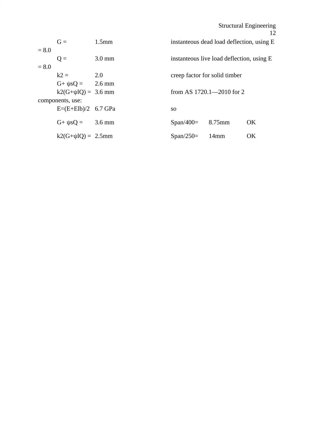
Check limiting deflection
E = 8.0 GPa f or MSG8, from AS 1720.1—2010,
Elb = 5.4 GPa lower bound modulus of elasticity,
Structural Engineering
12
G = 1.5mm instanteous dead load deflection, using E
= 8.0
Q = 3.0 mm instanteous live load deflection, using E
= 8.0
k2 = 2.0 creep factor for solid timber
G+ ψsQ = 2.6 mm
k2(G+ψlQ) = 3.6 mm from AS 1720.1—2010 for 2
components, use:
E=(E+Elb)/2 6.7 GPa so
G+ ψsQ = 3.6 mm Span/400= 8.75mm OK
k2(G+ψlQ) = 2.5mm Span/250= 14mm OK
⊘ This is a preview!⊘
Do you want full access?
Subscribe today to unlock all pages.

Trusted by 1+ million students worldwide
1 out of 13
Related Documents
Your All-in-One AI-Powered Toolkit for Academic Success.
+13062052269
info@desklib.com
Available 24*7 on WhatsApp / Email
![[object Object]](/_next/static/media/star-bottom.7253800d.svg)
Unlock your academic potential
Copyright © 2020–2025 A2Z Services. All Rights Reserved. Developed and managed by ZUCOL.


