Report on Developing a Student Enrollment for Job Database System
VerifiedAdded on 2020/11/23
|39
|3339
|277
Report
AI Summary
This report details the design and implementation of a student enrollment database system. The introduction provides context for database management systems and their importance. Task 1 focuses on developing an entity-relationship (ER) model, including identifying entities (Student, Course, Job, Roaster, Volunteers, Facility), attributes, and relationships. The business case for entity relations is discussed, followed by mapping the ER diagram to a set of relations in Third Normal Form (3NF), covering 1NF, 2NF, and 3NF normalization. Task 2 involves implementing a data dictionary to create a relational database in PhpMyAdmin, along with associated database queries and the design of forms and reports. The report includes tables showcasing data structures, relationships, and normalization processes. The conclusion summarizes the findings and the references provide the sources used to create the report.

Student Enrolment for Job
Paraphrase This Document
Need a fresh take? Get an instant paraphrase of this document with our AI Paraphraser
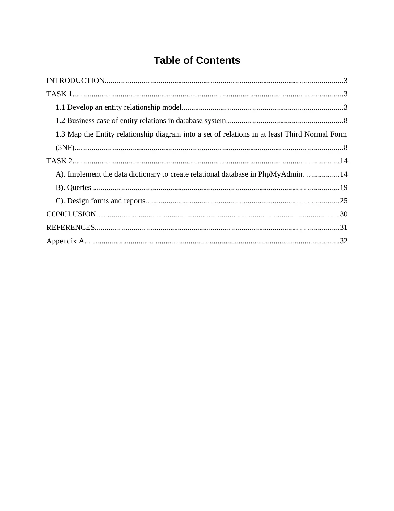
Table of Contents
INTRODUCTION...........................................................................................................................3
TASK 1............................................................................................................................................3
1.1 Develop an entity relationship model...................................................................................3
1.2 Business case of entity relations in database system............................................................8
1.3 Map the Entity relationship diagram into a set of relations in at least Third Normal Form
(3NF)...........................................................................................................................................8
TASK 2..........................................................................................................................................14
A). Implement the data dictionary to create relational database in PhpMyAdmin. .................14
B). Queries ...............................................................................................................................19
C). Design forms and reports....................................................................................................25
CONCLUSION..............................................................................................................................30
REFERENCES..............................................................................................................................31
Appendix A....................................................................................................................................32
INTRODUCTION
Database management system is a type of software that helps for managing the large
number of data in proper manner. This software will possible for create, read, delete and update
the data in the database system. It is an essential for DBMS to serve as an interface between the
data and end users. This assignment will discuss about the database that stored all the
information of student in proper manner. It will discover the Entity relationship diagram to show
the relationship between different entities. This report will discuss about the Normalization
forms like 1NF, 2NF, 3NF. These forms are useful in tables to create relationship between them.
TASK 1
1.1 Develop an entity relationship model
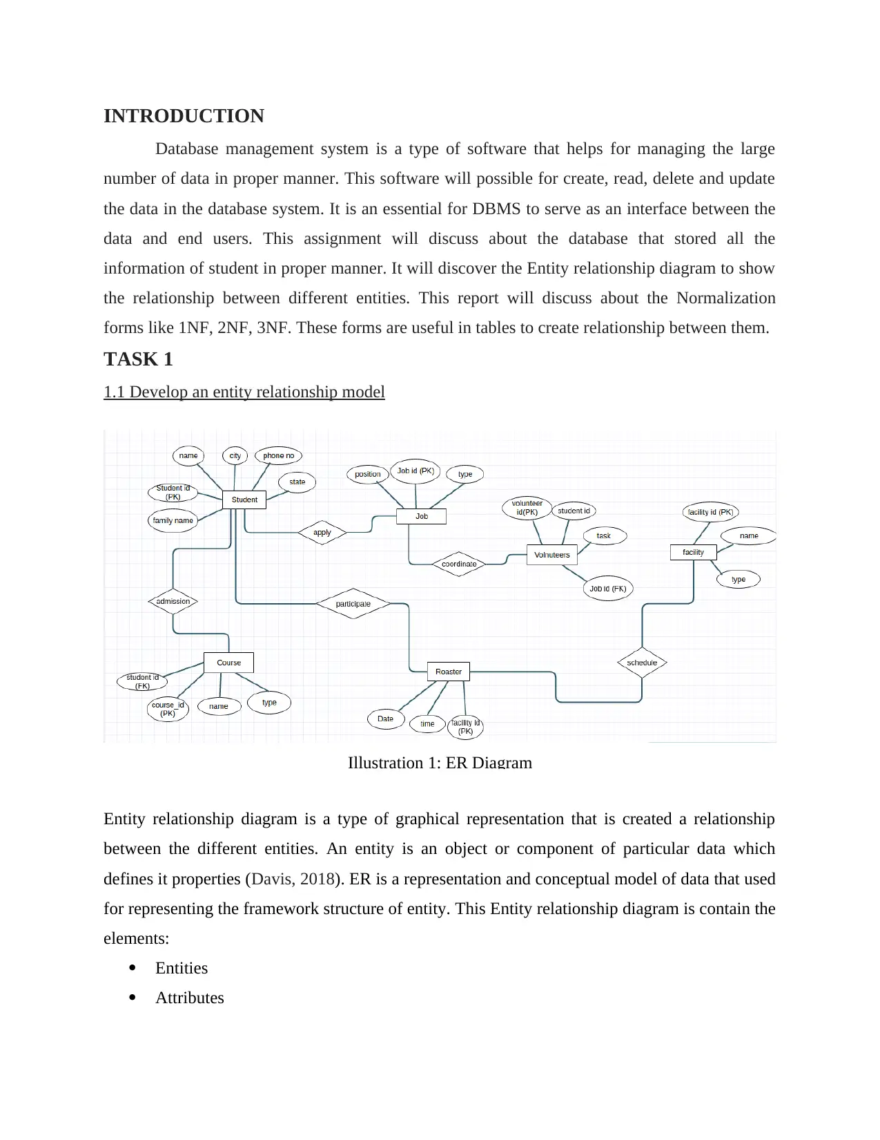
Entity relationship diagram is a type of graphical representation that is created a relationship
between the different entities. An entity is an object or component of particular data which
defines it properties (Davis, 2018). ER is a representation and conceptual model of data that used
for representing the framework structure of entity. This Entity relationship diagram is contain the
elements:
Entities
Attributes
Illustration 1: ER Diagram
⊘ This is a preview!⊘
Do you want full access?
Subscribe today to unlock all pages.

Trusted by 1+ million students worldwide
Relationship
For creating ER diagram that involved some specific steps:
First of all, defining and identifying the entities
Determining all the relationship or interaction among the entities
Analysing the nature of interaction and identifying the cardinality of the relationships
At last, it is creating the Entity relationship diagram in effective ways.
A). Demonstrate all necessary entities
Student
Course
Job
Roaster
Volunteers
Facility
These are the different type of entities help for creating an effective relationship database system
where all entities are interconnected to each other.
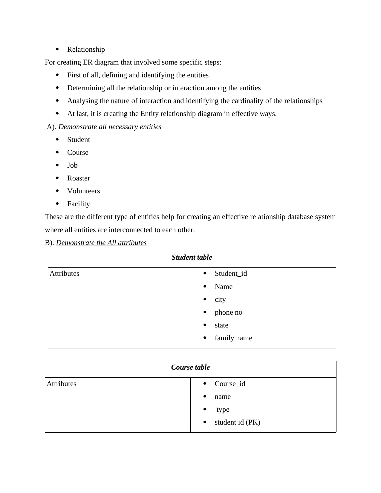
B). Demonstrate the All attributes
Student table
Attributes Student_id
Name
city
phone no
state
family name
Course table
Attributes Course_id
name
type
student id (PK)
Paraphrase This Document
Need a fresh take? Get an instant paraphrase of this document with our AI Paraphraser
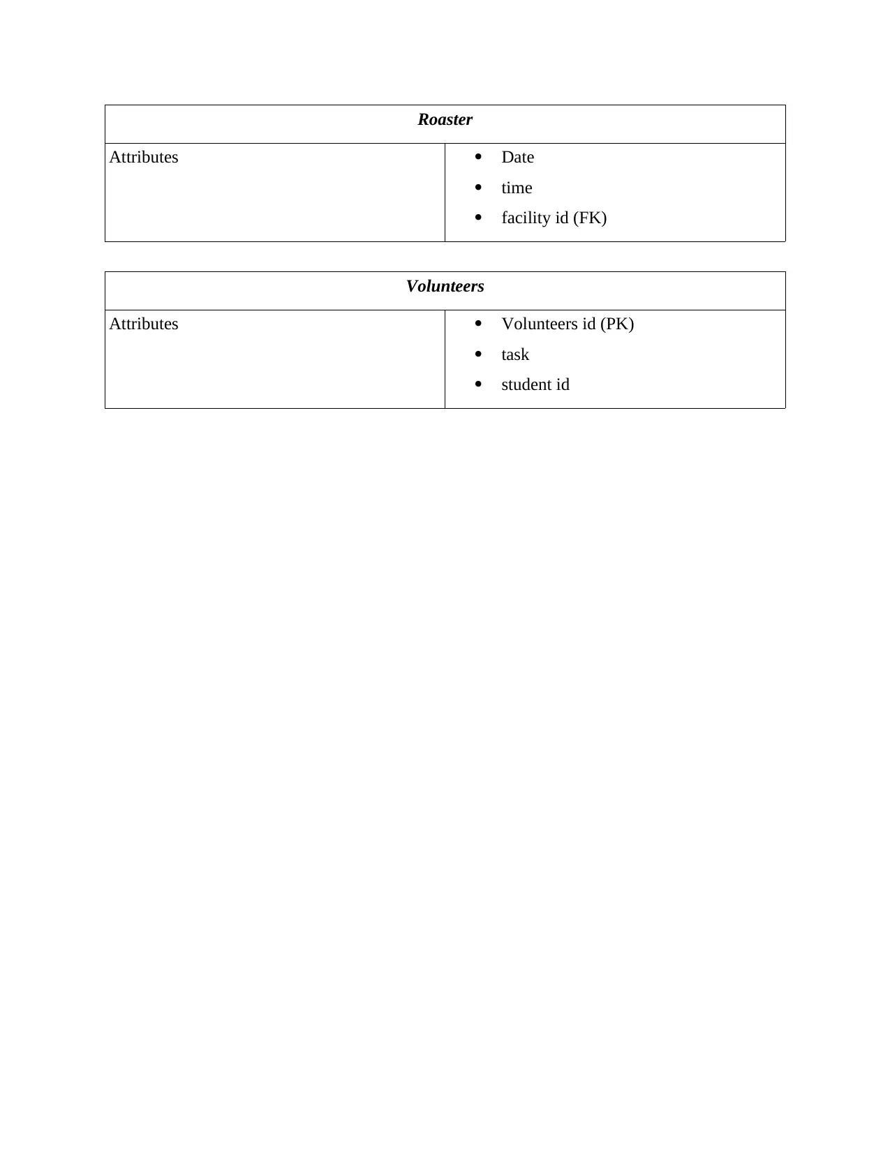
Roaster
Attributes Date
time
facility id (FK)
Volunteers
Attributes Volunteers id (PK)
task
student id
Attributes Date
time
facility id (FK)
Volunteers
Attributes Volunteers id (PK)
task
student id
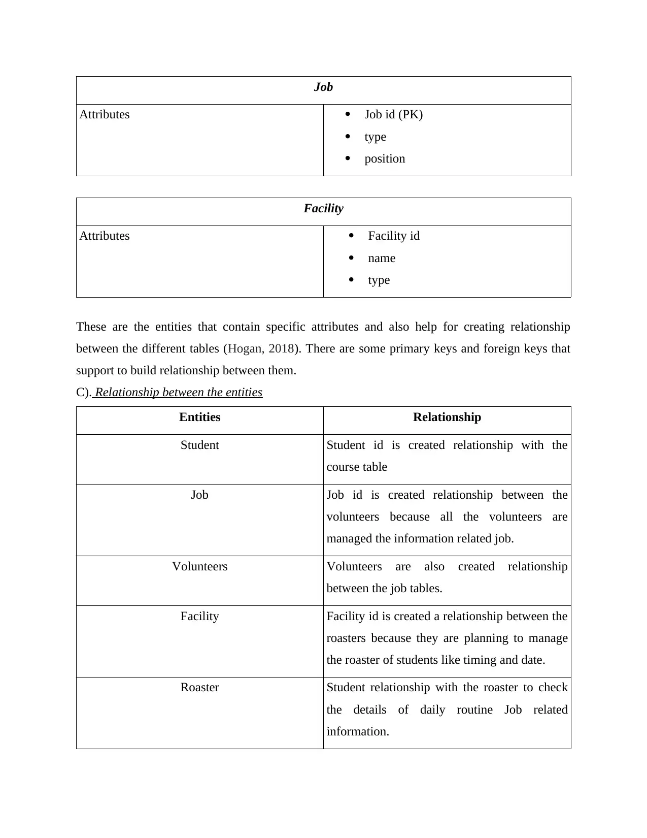
Job
Attributes Job id (PK)
type
position
Facility
Attributes Facility id
name
type
These are the entities that contain specific attributes and also help for creating relationship
between the different tables (Hogan, 2018). There are some primary keys and foreign keys that
support to build relationship between them.
C). Relationship between the entities
Entities Relationship
Student Student id is created relationship with the
course table
Job Job id is created relationship between the
volunteers because all the volunteers are
managed the information related job.
Volunteers Volunteers are also created relationship
between the job tables.
Facility Facility id is created a relationship between the
roasters because they are planning to manage
the roaster of students like timing and date.
Roaster Student relationship with the roaster to check
the details of daily routine Job related
information.
⊘ This is a preview!⊘
Do you want full access?
Subscribe today to unlock all pages.

Trusted by 1+ million students worldwide
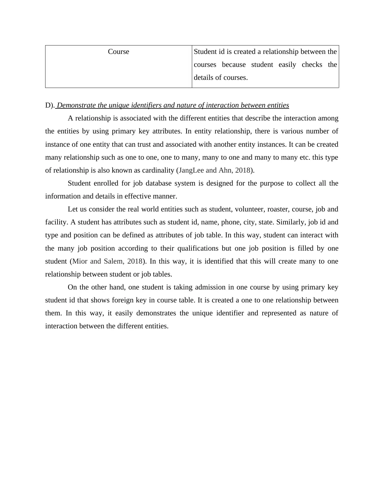
Course Student id is created a relationship between the
courses because student easily checks the
details of courses.
D). Demonstrate the unique identifiers and nature of interaction between entities
A relationship is associated with the different entities that describe the interaction among
the entities by using primary key attributes. In entity relationship, there is various number of
instance of one entity that can trust and associated with another entity instances. It can be created
many relationship such as one to one, one to many, many to one and many to many etc. this type
of relationship is also known as cardinality (JangLee and Ahn, 2018).
Student enrolled for job database system is designed for the purpose to collect all the
information and details in effective manner.
Let us consider the real world entities such as student, volunteer, roaster, course, job and
facility. A student has attributes such as student id, name, phone, city, state. Similarly, job id and
type and position can be defined as attributes of job table. In this way, student can interact with
the many job position according to their qualifications but one job position is filled by one
student (Mior and Salem, 2018). In this way, it is identified that this will create many to one
relationship between student or job tables.
On the other hand, one student is taking admission in one course by using primary key
student id that shows foreign key in course table. It is created a one to one relationship between
them. In this way, it easily demonstrates the unique identifier and represented as nature of
interaction between the different entities.
Paraphrase This Document
Need a fresh take? Get an instant paraphrase of this document with our AI Paraphraser
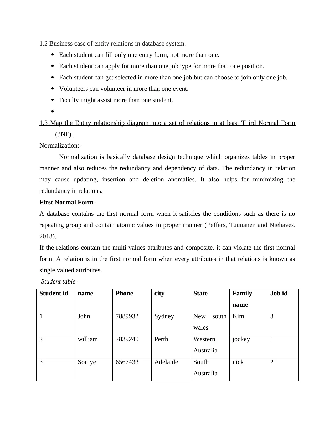
1.2 Business case of entity relations in database system.
Each student can fill only one entry form, not more than one.
Each student can apply for more than one job type for more than one position.
Each student can get selected in more than one job but can choose to join only one job.
Volunteers can volunteer in more than one event.
Faculty might assist more than one student.
1.3 Map the Entity relationship diagram into a set of relations in at least Third Normal Form
(3NF).
Normalization:-
Normalization is basically database design technique which organizes tables in proper
manner and also reduces the redundancy and dependency of data. The redundancy in relation
may cause updating, insertion and deletion anomalies. It also helps for minimizing the
redundancy in relations.
First Normal Form-
A database contains the first normal form when it satisfies the conditions such as there is no
repeating group and contain atomic values in proper manner (Peffers, Tuunanen and Niehaves,
2018).
If the relations contain the multi values attributes and composite, it can violate the first normal
form. A relation is in the first normal form when every attributes in that relations is known as
single valued attributes.
Student table-
Student id name Phone city State Family
name
Job id
1 John 7889932 Sydney New south
wales
Kim 3
2 william 7839240 Perth Western
Australia
jockey 1
3 Somye 6567433 Adelaide South
Australia
nick 2
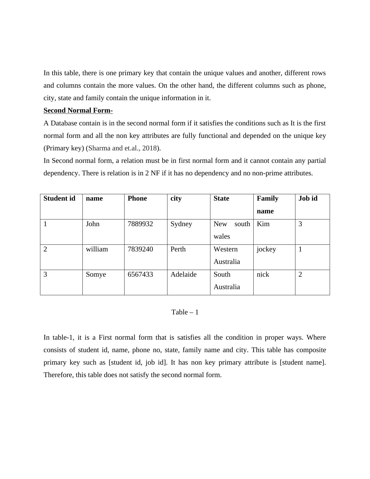
In this table, there is one primary key that contain the unique values and another, different rows
and columns contain the more values. On the other hand, the different columns such as phone,
city, state and family contain the unique information in it.
Second Normal Form-
A Database contain is in the second normal form if it satisfies the conditions such as It is the first
normal form and all the non key attributes are fully functional and depended on the unique key
(Primary key) (Sharma and et.al., 2018).
In Second normal form, a relation must be in first normal form and it cannot contain any partial
dependency. There is relation is in 2 NF if it has no dependency and no non-prime attributes.
Student id name Phone city State Family
name
Job id
1 John 7889932 Sydney New south
wales
Kim 3
2 william 7839240 Perth Western
Australia
jockey 1
3 Somye 6567433 Adelaide South
Australia
nick 2
Table – 1
In table-1, it is a First normal form that is satisfies all the condition in proper ways. Where
consists of student id, name, phone no, state, family name and city. This table has composite
primary key such as [student id, job id]. It has non key primary attribute is [student name].
Therefore, this table does not satisfy the second normal form.
⊘ This is a preview!⊘
Do you want full access?
Subscribe today to unlock all pages.

Trusted by 1+ million students worldwide
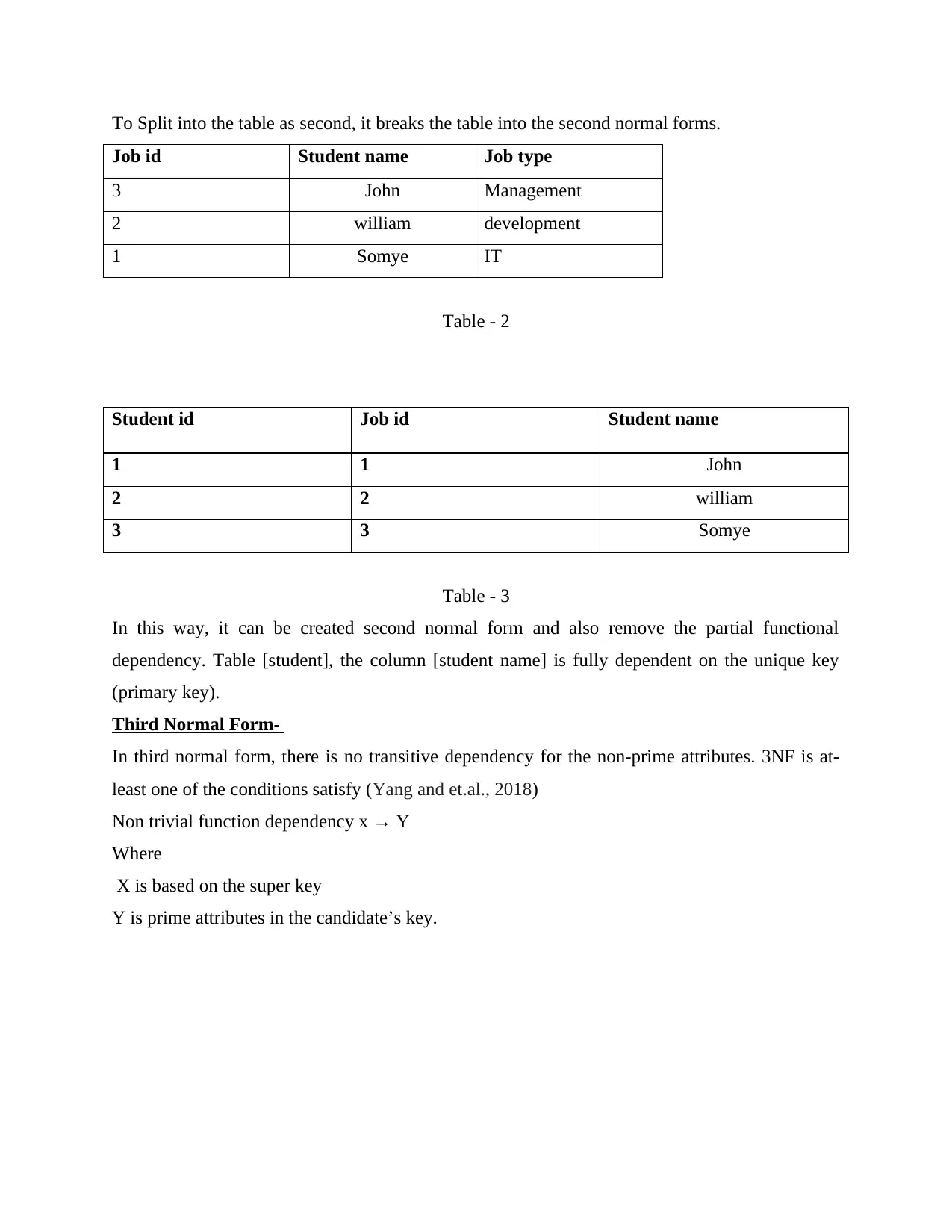
To Split into the table as second, it breaks the table into the second normal forms.
Job id Student name Job type
3 John Management
2 william development
1 Somye IT
Table - 2
Student id Job id Student name
1 1 John
2 2 william
3 3 Somye
Table - 3
In this way, it can be created second normal form and also remove the partial functional
dependency. Table [student], the column [student name] is fully dependent on the unique key
(primary key).
Third Normal Form-
In third normal form, there is no transitive dependency for the non-prime attributes. 3NF is at-
least one of the conditions satisfy (Yang and et.al., 2018)
Non trivial function dependency x → Y
Where
X is based on the super key
Y is prime attributes in the candidate’s key.
Paraphrase This Document
Need a fresh take? Get an instant paraphrase of this document with our AI Paraphraser
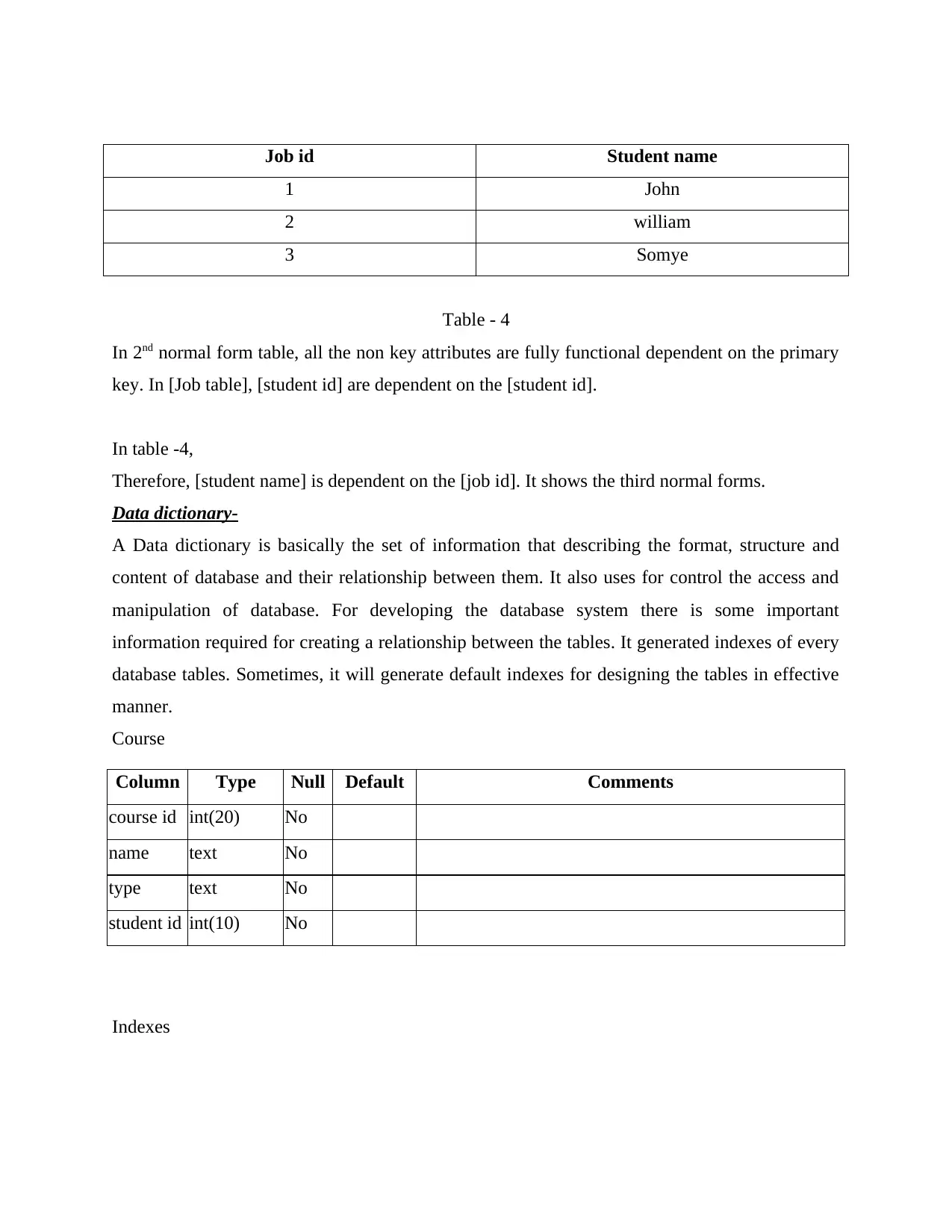
Job id Student name
1 John
2 william
3 Somye
Table - 4
In 2nd normal form table, all the non key attributes are fully functional dependent on the primary
key. In [Job table], [student id] are dependent on the [student id].
In table -4,
Therefore, [student name] is dependent on the [job id]. It shows the third normal forms.
Data dictionary-
A Data dictionary is basically the set of information that describing the format, structure and
content of database and their relationship between them. It also uses for control the access and
manipulation of database. For developing the database system there is some important
information required for creating a relationship between the tables. It generated indexes of every
database tables. Sometimes, it will generate default indexes for designing the tables in effective
manner.
Course
Column Type Null Default Comments
course id int(20) No
name text No
type text No
student id int(10) No
Indexes
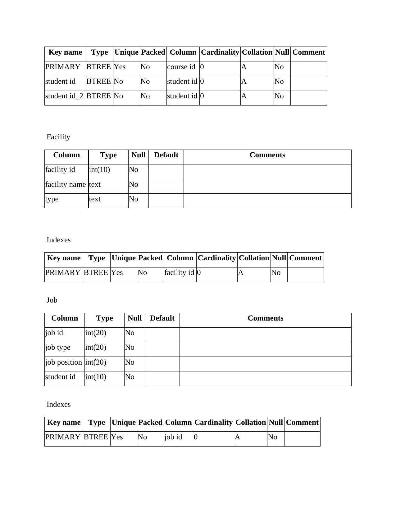
Key name Type Unique Packed Column Cardinality Collation Null Comment
PRIMARY BTREE Yes No course id 0 A No
student id BTREE No No student id 0 A No
student id_2 BTREE No No student id 0 A No
Facility
Column Type Null Default Comments
facility id int(10) No
facility name text No
type text No
Indexes
Key name Type Unique Packed Column Cardinality Collation Null Comment
PRIMARY BTREE Yes No facility id 0 A No
Job
Column Type Null Default Comments
job id int(20) No
job type int(20) No
job position int(20) No
student id int(10) No
Indexes
Key name Type Unique Packed Column Cardinality Collation Null Comment
PRIMARY BTREE Yes No job id 0 A No
⊘ This is a preview!⊘
Do you want full access?
Subscribe today to unlock all pages.

Trusted by 1+ million students worldwide
1 out of 39
Related Documents
Your All-in-One AI-Powered Toolkit for Academic Success.
+13062052269
info@desklib.com
Available 24*7 on WhatsApp / Email
![[object Object]](/_next/static/media/star-bottom.7253800d.svg)
Unlock your academic potential
Copyright © 2020–2025 A2Z Services. All Rights Reserved. Developed and managed by ZUCOL.


