SEE332 - Theoretical Background of Electrical Engineering Report
VerifiedAdded on 2023/01/18
|9
|1452
|51
Report
AI Summary
This report provides a comprehensive overview of synchronous machines and AC transmission lines, fundamental components in electrical engineering. It begins by defining synchronous machines, differentiating between synchronous motors and generators, and explaining their operational principles, constructional features, and applications. The report delves into the workings of synchronous generators, including the generation of stator induced voltage and the concept of synchronous speed. It also discusses the parallel operation of synchronous generators. The second part of the report focuses on AC transmission lines, outlining their purpose in transferring electrical power from generating stations to distribution networks. It covers the equivalent circuit of AC transmission lines, the types of conductors used, and the characteristics of active and reactive power flow. The report also explores the voltage regulation characteristics of AC transmission lines under various load conditions. Overall, the report provides a detailed understanding of the theoretical background of synchronous machines and AC transmission lines, offering valuable insights for electrical engineering students.
Running head: THEORETICAL BACKGROUND ELECTRICAL ENGINEERING
Theoretical background Electrical engineering
Name of the student:
Name of the University:
Theoretical background Electrical engineering
Name of the student:
Name of the University:
Paraphrase This Document
Need a fresh take? Get an instant paraphrase of this document with our AI Paraphraser
1THEORETICAL BACKGROUND ELECTRICAL ENGINEERING
Synchronous Machine
Synchronous machine is a combination of synchronous motors and asynchronous
generator. Application of DC system is always beneficial than the AC systems. Synchronous
machine rotates in a steady speed known as synchronous speed in the stable situations. In case of
synchronous machine the dc excitation is supplied to the rotor field winding and then the
alteration current (AC) flows or directed to the armature winding. In order to produce the field
flux permanent magnet is used in the permanent magnet synchronous machine. It has been
determined that, as per requirements the synchronous machine can be used either as a motor or
as a generator. The AC system is always utterly used for transmission, distribution and power
generation.
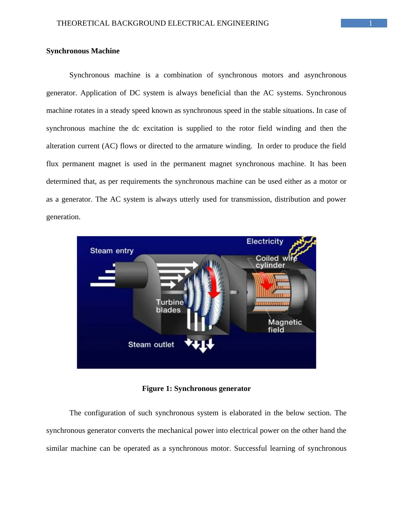
Figure 1: Synchronous generator
The configuration of such synchronous system is elaborated in the below section. The
synchronous generator converts the mechanical power into electrical power on the other hand the
similar machine can be operated as a synchronous motor. Successful learning of synchronous
2THEORETICAL BACKGROUND ELECTRICAL ENGINEERING
machine will help the learners to understand its operational principles and features of both the
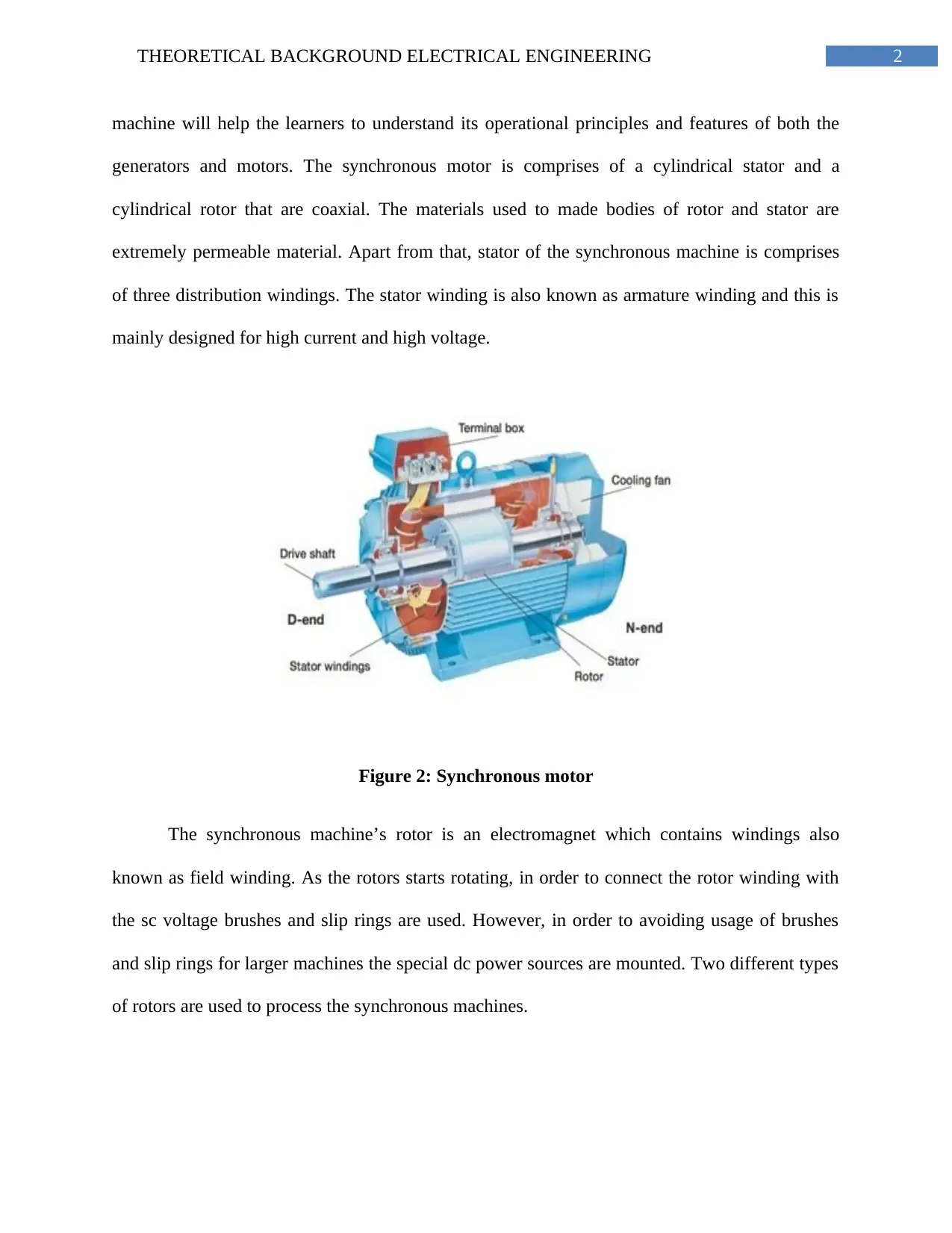
generators and motors. The synchronous motor is comprises of a cylindrical stator and a
cylindrical rotor that are coaxial. The materials used to made bodies of rotor and stator are
extremely permeable material. Apart from that, stator of the synchronous machine is comprises
of three distribution windings. The stator winding is also known as armature winding and this is
mainly designed for high current and high voltage.
Figure 2: Synchronous motor
The synchronous machine’s rotor is an electromagnet which contains windings also
known as field winding. As the rotors starts rotating, in order to connect the rotor winding with
the sc voltage brushes and slip rings are used. However, in order to avoiding usage of brushes
and slip rings for larger machines the special dc power sources are mounted. Two different types
of rotors are used to process the synchronous machines.
⊘ This is a preview!⊘
Do you want full access?
Subscribe today to unlock all pages.

Trusted by 1+ million students worldwide
3THEORETICAL BACKGROUND ELECTRICAL ENGINEERING
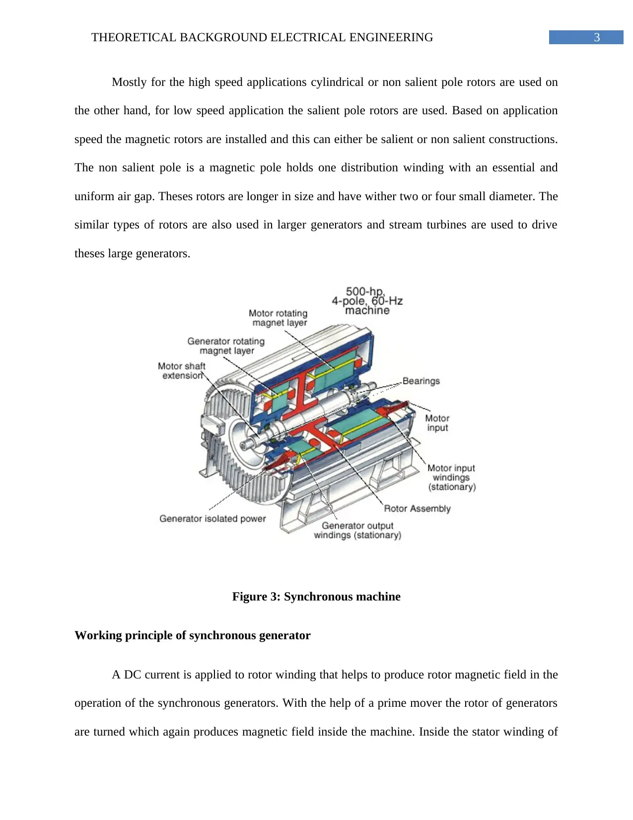
Mostly for the high speed applications cylindrical or non salient pole rotors are used on
the other hand, for low speed application the salient pole rotors are used. Based on application
speed the magnetic rotors are installed and this can either be salient or non salient constructions.
The non salient pole is a magnetic pole holds one distribution winding with an essential and
uniform air gap. Theses rotors are longer in size and have wither two or four small diameter. The
similar types of rotors are also used in larger generators and stream turbines are used to drive
theses large generators.
Figure 3: Synchronous machine
Working principle of synchronous generator
A DC current is applied to rotor winding that helps to produce rotor magnetic field in the
operation of the synchronous generators. With the help of a prime mover the rotor of generators
are turned which again produces magnetic field inside the machine. Inside the stator winding of
Paraphrase This Document
Need a fresh take? Get an instant paraphrase of this document with our AI Paraphraser
4THEORETICAL BACKGROUND ELECTRICAL ENGINEERING
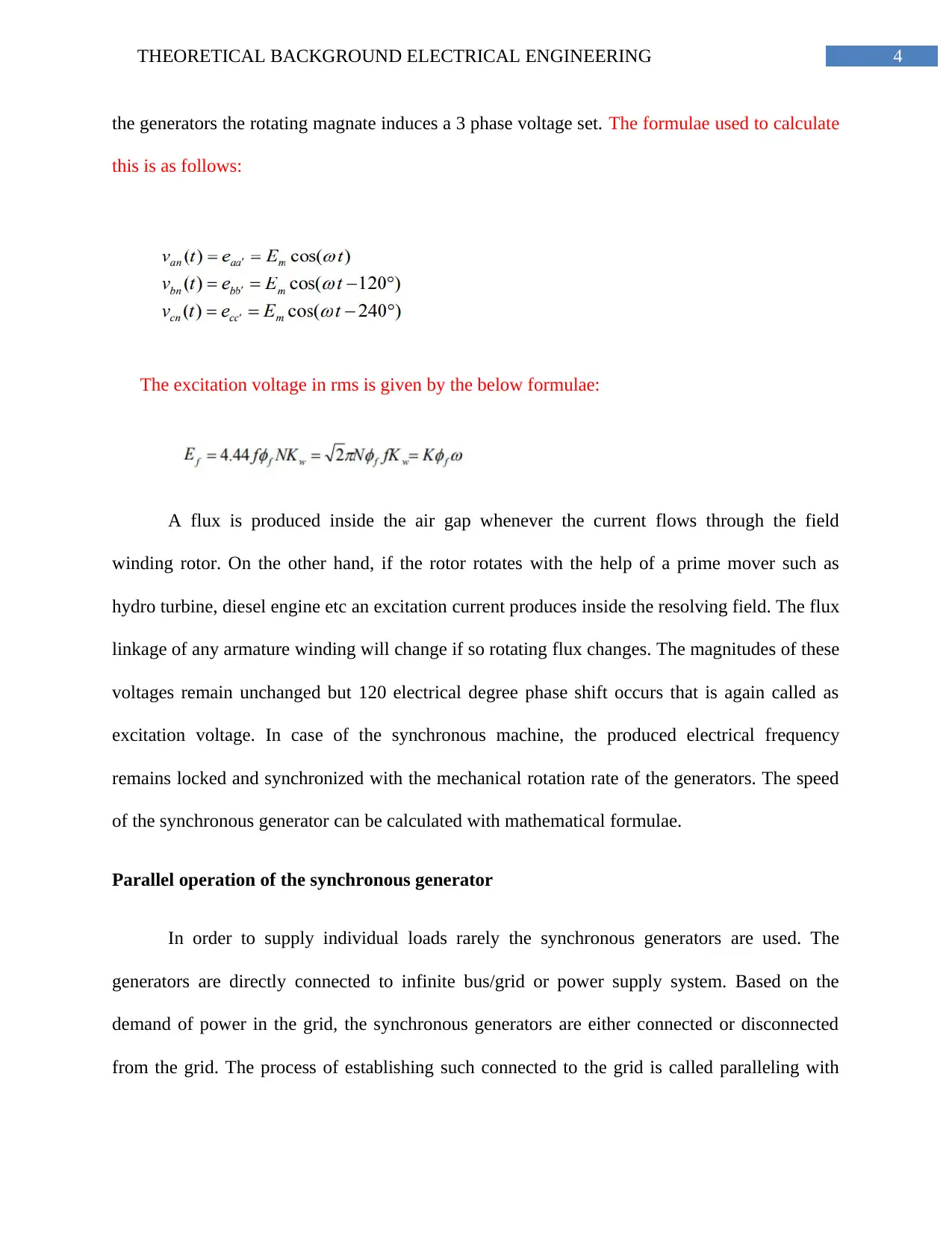
the generators the rotating magnate induces a 3 phase voltage set. The formulae used to calculate
this is as follows:
The excitation voltage in rms is given by the below formulae:
A flux is produced inside the air gap whenever the current flows through the field
winding rotor. On the other hand, if the rotor rotates with the help of a prime mover such as
hydro turbine, diesel engine etc an excitation current produces inside the resolving field. The flux
linkage of any armature winding will change if so rotating flux changes. The magnitudes of these
voltages remain unchanged but 120 electrical degree phase shift occurs that is again called as
excitation voltage. In case of the synchronous machine, the produced electrical frequency
remains locked and synchronized with the mechanical rotation rate of the generators. The speed
of the synchronous generator can be calculated with mathematical formulae.
Parallel operation of the synchronous generator
In order to supply individual loads rarely the synchronous generators are used. The
generators are directly connected to infinite bus/grid or power supply system. Based on the
demand of power in the grid, the synchronous generators are either connected or disconnected
from the grid. The process of establishing such connected to the grid is called paralleling with
5THEORETICAL BACKGROUND ELECTRICAL ENGINEERING
infinite bus. Mostly generators are connected paralelly and some of the advantages for this
operation are mentioned in the below section:
Bigger amount of load can be supplied by paralelly connected several generators
than a single machine
The parallel connection increases the power system’s reliability
If a single generator fails to produce proper power supply then it is not necessary
that the entire process fails to produce current supply
Before connecting a generator to the infinite bus or running generator it must be
ensured that the voltage, frequency, phase angle and phase sequence are properly
synchronized
⊘ This is a preview!⊘
Do you want full access?
Subscribe today to unlock all pages.

Trusted by 1+ million students worldwide
6THEORETICAL BACKGROUND ELECTRICAL ENGINEERING
AC transmission Lines
It is found that electrical power produces from the electric power stations such as solar
power plant, hydro power station, wind turbine etc. Then the electrical power is transferred
through transmission lines ranges 138 KV and 756 KV. The current flowing in the transmission
line is enables by the high voltages. On the other hand, the rate of power loss decreases if lower
rate of current flow through the transmission line. In fact, size of the wires also reduces with the
rate of the power transmitting through the line. It basically happens because in most cases the
transmission lines are used for long distance power flow. Reduces size of the wire also reduces
the net investment cost or price of the electricity transmission.
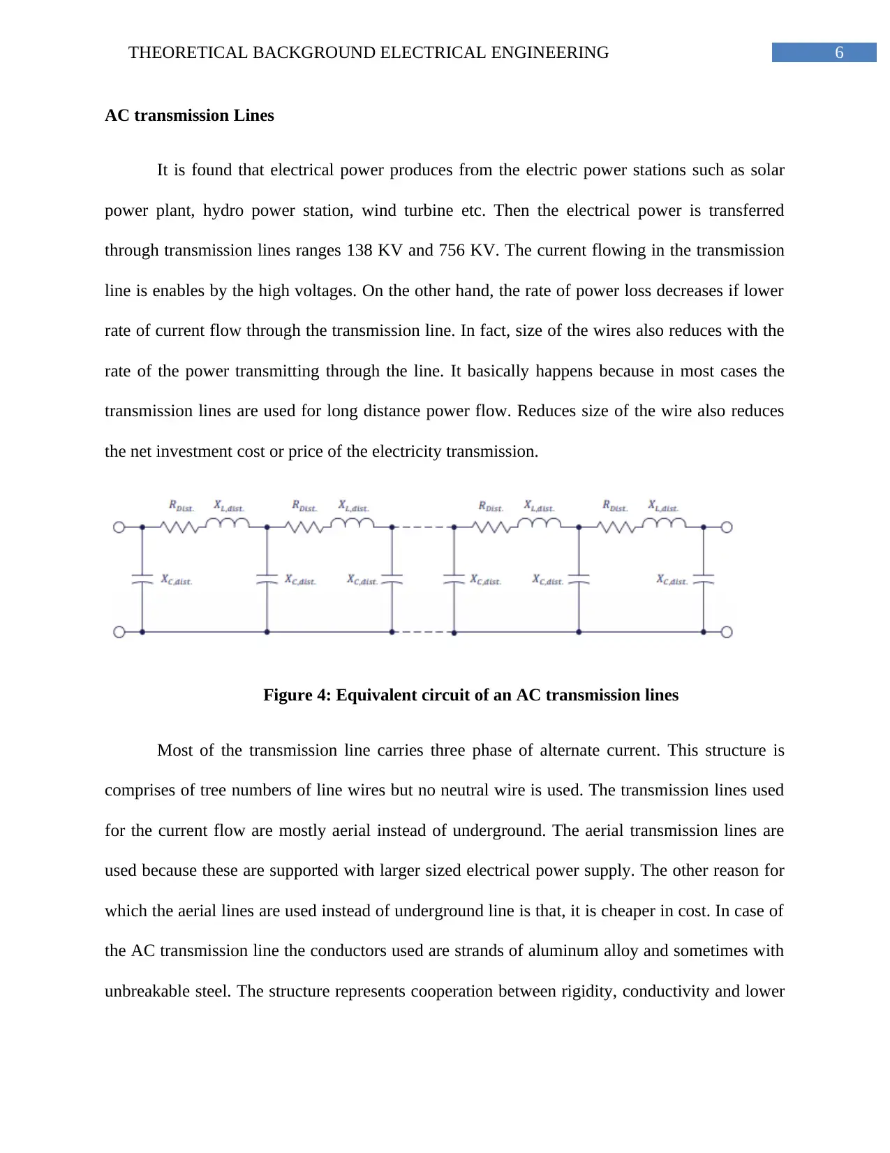
Figure 4: Equivalent circuit of an AC transmission lines
Most of the transmission line carries three phase of alternate current. This structure is
comprises of tree numbers of line wires but no neutral wire is used. The transmission lines used
for the current flow are mostly aerial instead of underground. The aerial transmission lines are
used because these are supported with larger sized electrical power supply. The other reason for
which the aerial lines are used instead of underground line is that, it is cheaper in cost. In case of
the AC transmission line the conductors used are strands of aluminum alloy and sometimes with
unbreakable steel. The structure represents cooperation between rigidity, conductivity and lower
Paraphrase This Document
Need a fresh take? Get an instant paraphrase of this document with our AI Paraphraser
7THEORETICAL BACKGROUND ELECTRICAL ENGINEERING
cost transmission lines. The AC transmission lines are mainly used for transferring active power,
which is actually used to accomplish works.
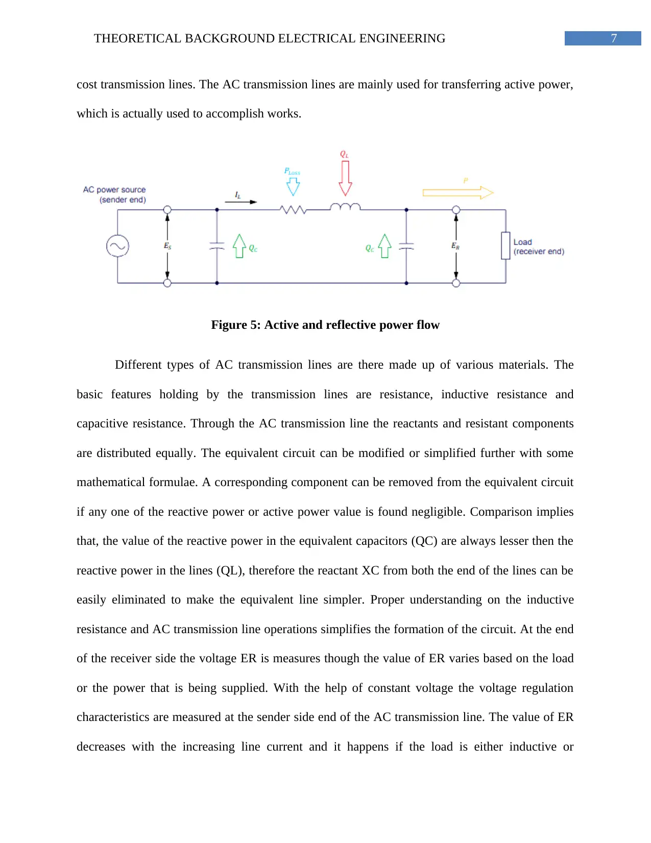
Figure 5: Active and reflective power flow
Different types of AC transmission lines are there made up of various materials. The
basic features holding by the transmission lines are resistance, inductive resistance and
capacitive resistance. Through the AC transmission line the reactants and resistant components
are distributed equally. The equivalent circuit can be modified or simplified further with some
mathematical formulae. A corresponding component can be removed from the equivalent circuit
if any one of the reactive power or active power value is found negligible. Comparison implies
that, the value of the reactive power in the equivalent capacitors (QC) are always lesser then the
reactive power in the lines (QL), therefore the reactant XC from both the end of the lines can be
easily eliminated to make the equivalent line simpler. Proper understanding on the inductive
resistance and AC transmission line operations simplifies the formation of the circuit. At the end
of the receiver side the voltage ER is measures though the value of ER varies based on the load
or the power that is being supplied. With the help of constant voltage the voltage regulation
characteristics are measured at the sender side end of the AC transmission line. The value of ER
decreases with the increasing line current and it happens if the load is either inductive or

8THEORETICAL BACKGROUND ELECTRICAL ENGINEERING
resistive. Similarly, while the load is capacitive, the value of voltage current increases with the
enhancing line current.
resistive. Similarly, while the load is capacitive, the value of voltage current increases with the
enhancing line current.
⊘ This is a preview!⊘
Do you want full access?
Subscribe today to unlock all pages.

Trusted by 1+ million students worldwide
1 out of 9
Related Documents
Your All-in-One AI-Powered Toolkit for Academic Success.
+13062052269
info@desklib.com
Available 24*7 on WhatsApp / Email
![[object Object]](/_next/static/media/star-bottom.7253800d.svg)
Unlock your academic potential
Copyright © 2020–2026 A2Z Services. All Rights Reserved. Developed and managed by ZUCOL.


