Transformer and Induction Motor Tests and Analysis

Verified

Added on  2023/06/05

|11
|927
|438
AI Summary
This chapter covers various tests and analysis of transformers and induction motors, including open circuit test, short circuit test, phasor diagrams, power factor, shunt parameters, series parameters, blocked rotor test, power flow diagram, starting torque, running torque, line reactance, fault analysis, and bus admittance matrix. It also provides study material, solved assignments, essays, and dissertations on these topics.

Contribute Materials

Your contribution can guide someone’s learning journey. Share your documents today.
Document Page
Chapter 3.2
a)
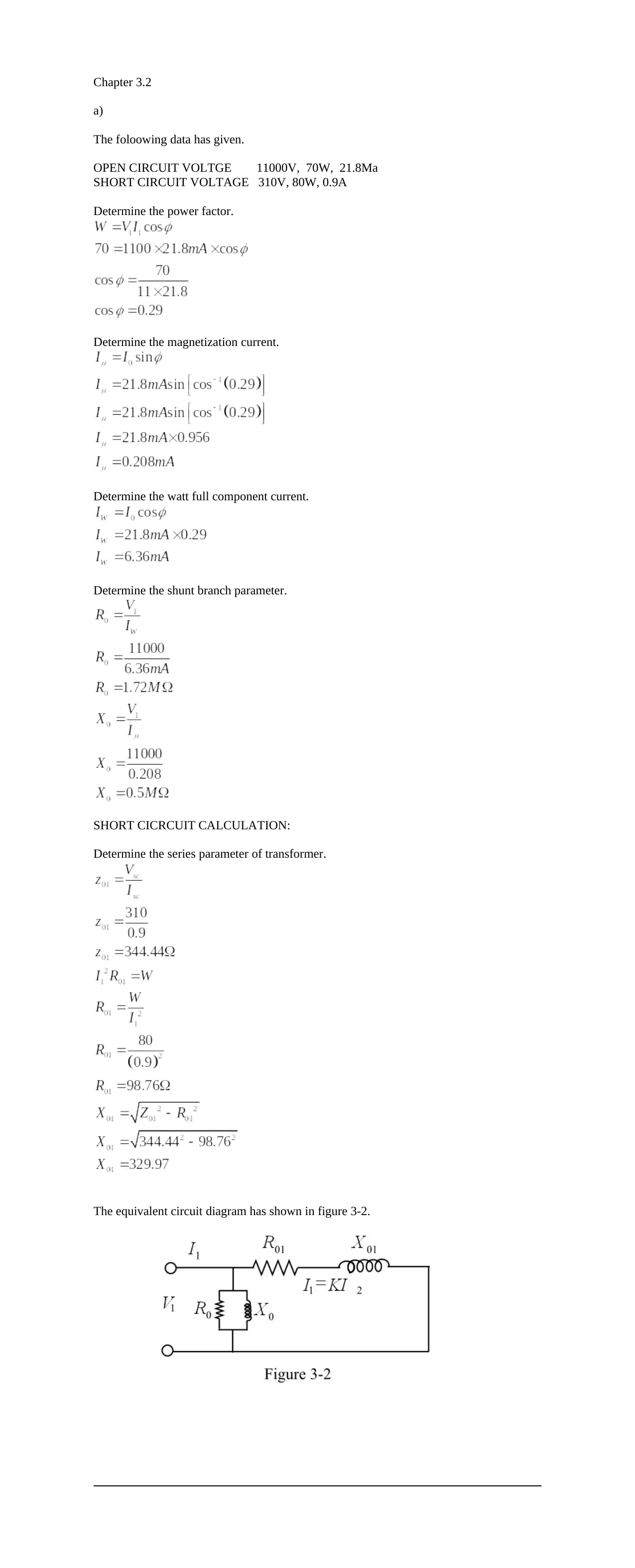
The foloowing data has given.
OPEN CIRCUIT VOLTGE 11000V, 70W, 21.8Ma
SHORT CIRCUIT VOLTAGE 310V, 80W, 0.9A
Determine the power factor.
Determine the magnetization current.
Determine the watt full component current.
Determine the shunt branch parameter.
SHORT CICRCUIT CALCULATION:
Determine the series parameter of transformer.
The equivalent circuit diagram has shown in figure 3-2.

Secure Best Marks with AI Grader

Need help grading? Try our AI Grader for instant feedback on your assignments.
Document Page
b)
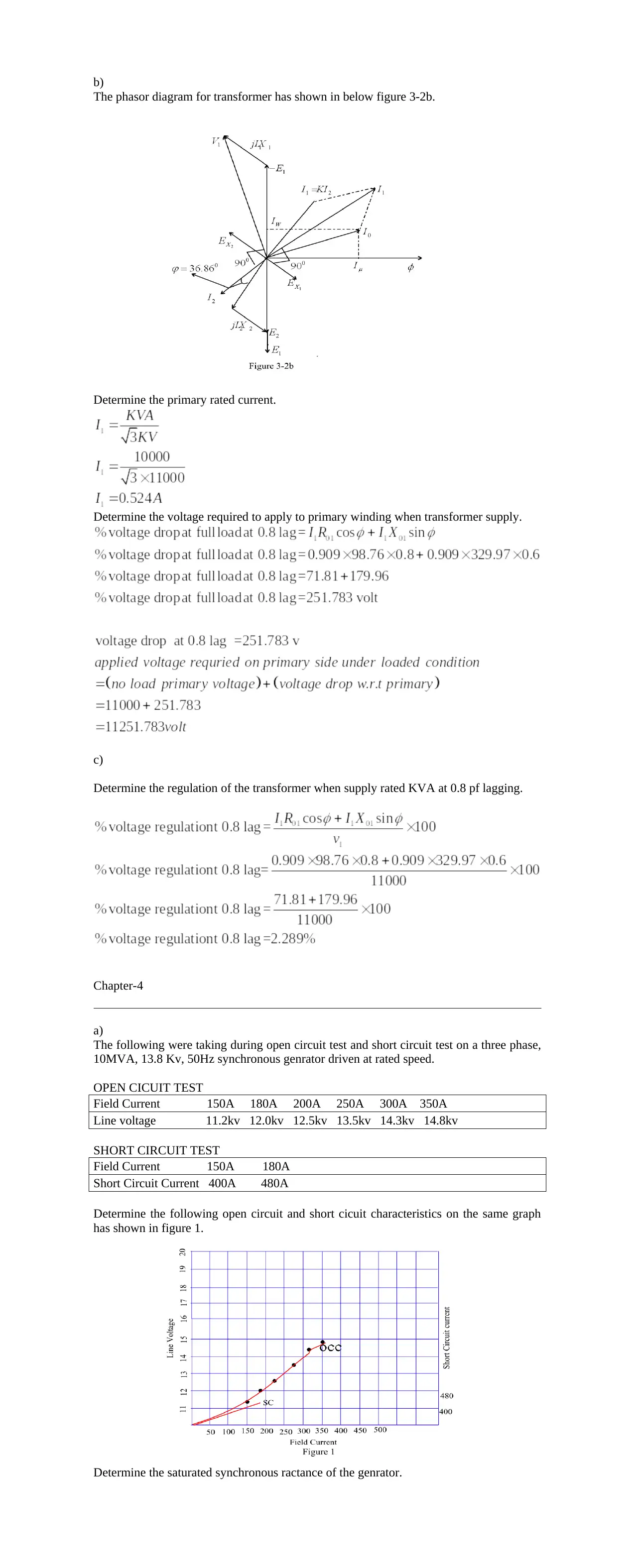
The phasor diagram for transformer has shown in below figure 3-2b.
Determine the primary rated current.
Determine the voltage required to apply to primary winding when transformer supply.
c)
Determine the regulation of the transformer when supply rated KVA at 0.8 pf lagging.
Chapter-4
a)
The following were taking during open circuit test and short circuit test on a three phase,
10MVA, 13.8 Kv, 50Hz synchronous genrator driven at rated speed.
OPEN CICUIT TEST
Field Current 150A 180A 200A 250A 300A 350A
Line voltage 11.2kv 12.0kv 12.5kv 13.5kv 14.3kv 14.8kv
SHORT CIRCUIT TEST
Field Current 150A 180A
Short Circuit Current 400A 480A
Determine the following open circuit and short cicuit characteristics on the same graph
has shown in figure 1.
Determine the saturated synchronous ractance of the genrator.
Document Page
b)
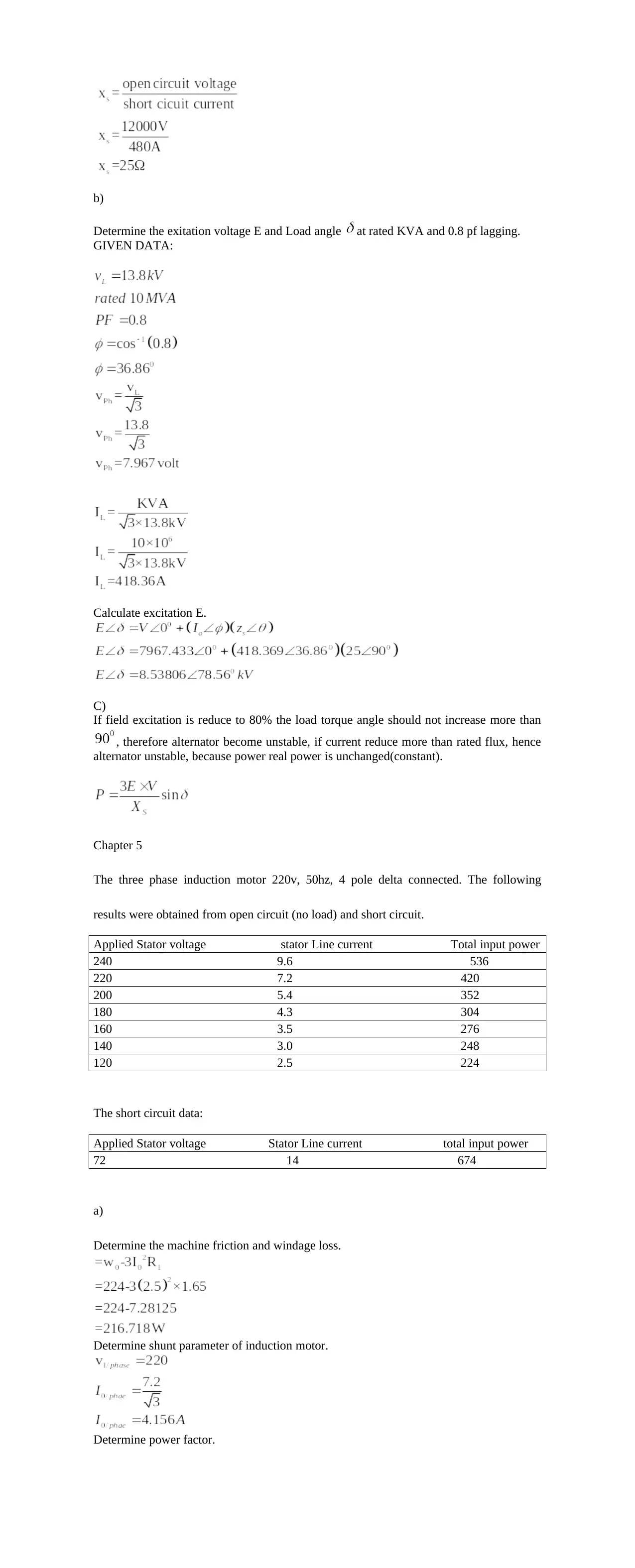
Determine the exitation voltage E and Load angle at rated KVA and 0.8 pf lagging.
GIVEN DATA:
Calculate excitation E.
C)
If field excitation is reduce to 80% the load torque angle should not increase more than
, therefore alternator become unstable, if current reduce more than rated flux, hence
alternator unstable, because power real power is unchanged(constant).
Chapter 5
The three phase induction motor 220v, 50hz, 4 pole delta connected. The following
results were obtained from open circuit (no load) and short circuit.
Applied Stator voltage stator Line current Total input power
240 9.6 536
220 7.2 420
200 5.4 352
180 4.3 304
160 3.5 276
140 3.0 248
120 2.5 224
The short circuit data:
Applied Stator voltage Stator Line current total input power
72 14 674
a)
Determine the machine friction and windage loss.
Determine shunt parameter of induction motor.
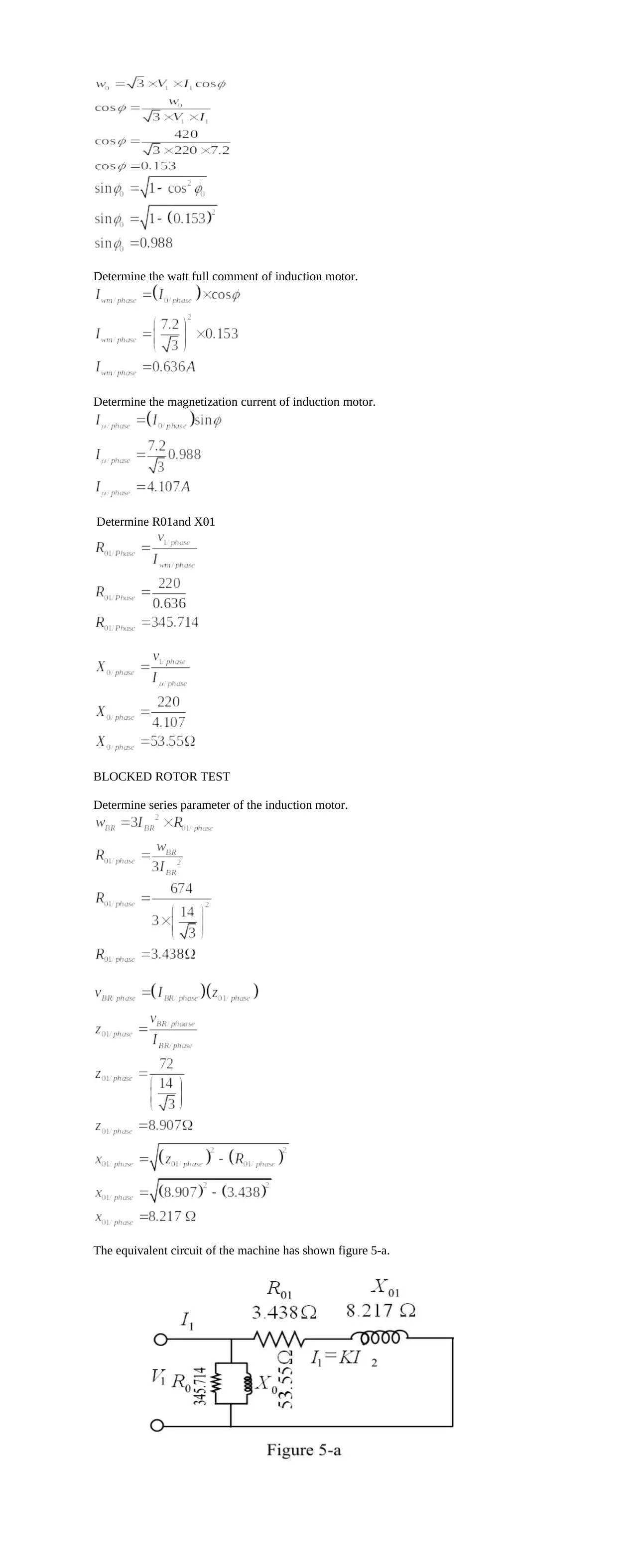
Determine power factor.
Document Page
Determine the watt full comment of induction motor.
Determine the magnetization current of induction motor.
Determine R01and X01
BLOCKED ROTOR TEST
Determine series parameter of the induction motor.
The equivalent circuit of the machine has shown figure 5-a.

Secure Best Marks with AI Grader

Need help grading? Try our AI Grader for instant feedback on your assignments.
Document Page
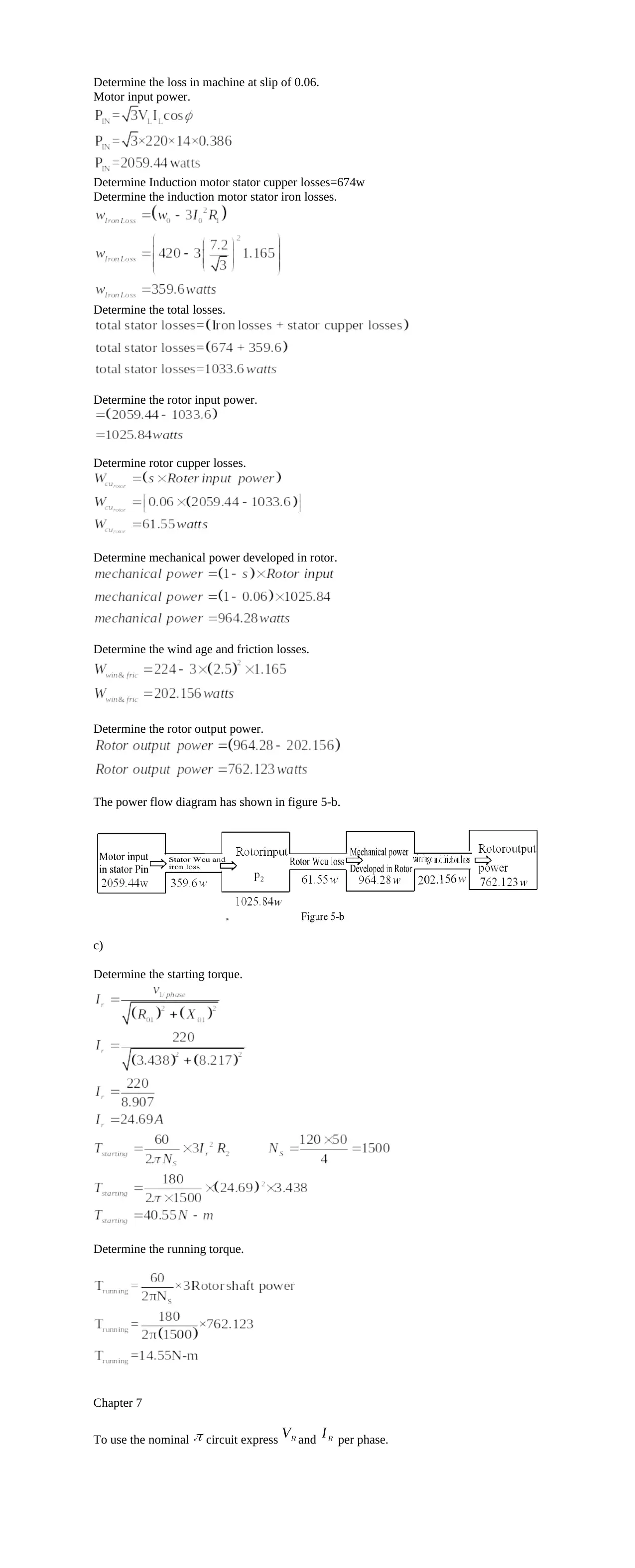
Determine the loss in machine at slip of 0.06.
Motor input power.
Determine Induction motor stator cupper losses=674w
Determine the induction motor stator iron losses.
Determine the total losses.
Determine the rotor input power.
Determine rotor cupper losses.
Determine mechanical power developed in rotor.
Determine the wind age and friction losses.
Determine the rotor output power.
The power flow diagram has shown in figure 5-b.
c)
Determine the starting torque.
Determine the running torque.
Chapter 7
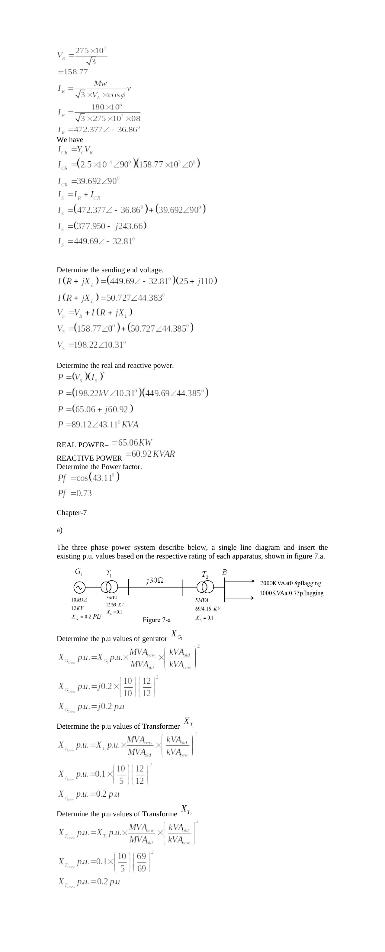
To use the nominal circuit express and per phase.
Document Page
We have
Determine the sending end voltage.
Determine the real and reactive power.
REAL POWER=
REACTIVE POWER
Determine the Power factor.
Chapter-7
a)
The three phase power system describe below, a single line diagram and insert the
existing p.u. values based on the respective rating of each apparatus, shown in figure 7.a.
Determine the p.u values of genrator
Determine the p.u values of Transformer
Determine the p.u values of Transforme
Document Page
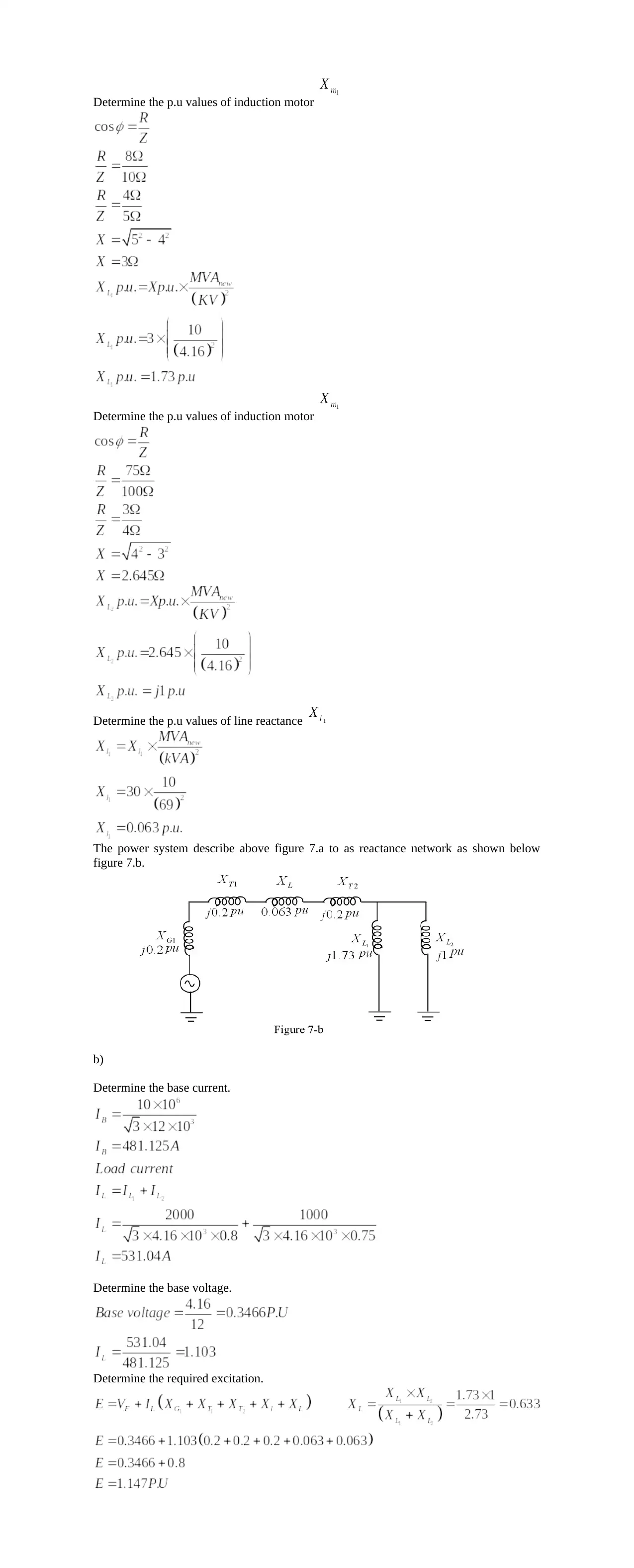
Determine the p.u values of induction motor
Determine the p.u values of line reactance
The power system describe above figure 7.a to as reactance network as shown below
figure 7.b.
b)
Determine the base current.
Determine the base voltage.
Determine the required excitation.

Paraphrase This Document

Need a fresh take? Get an instant paraphrase of this document with our AI Paraphraser
Document Page
c)
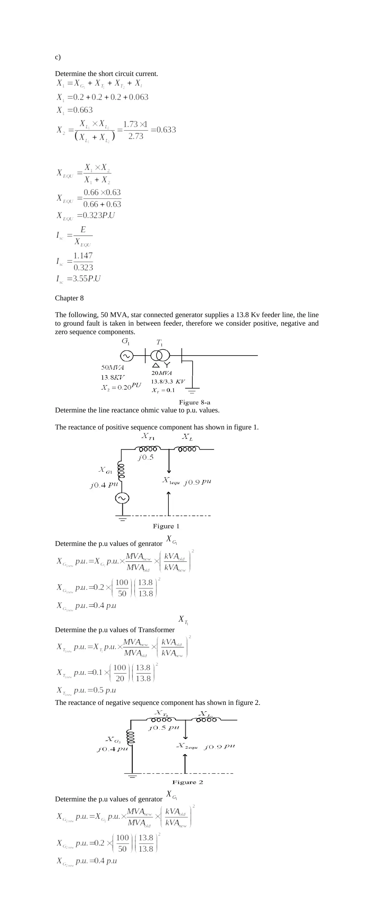
Determine the short circuit current.
Chapter 8
The following, 50 MVA, star connected generator supplies a 13.8 Kv feeder line, the line
to ground fault is taken in between feeder, therefore we consider positive, negative and
zero sequence components.
Determine the line reactance ohmic value to p.u. values.
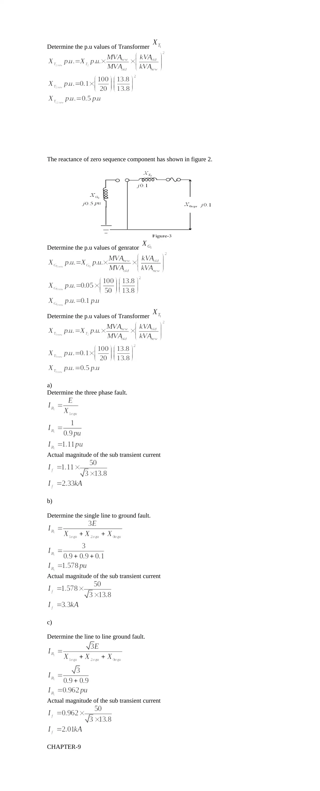
The reactance of positive sequence component has shown in figure 1.
Determine the p.u values of genrator
Determine the p.u values of Transformer
The reactance of negative sequence component has shown in figure 2.
Determine the p.u values of genrator
Document Page
Determine the p.u values of Transformer
The reactance of zero sequence component has shown in figure 2.
Determine the p.u values of genrator
Determine the p.u values of Transformer
a)
Determine the three phase fault.
Actual magnitude of the sub transient current
b)
Determine the single line to ground fault.
Actual magnitude of the sub transient current
c)
Determine the line to line ground fault.
Actual magnitude of the sub transient current
CHAPTER-9
Document Page
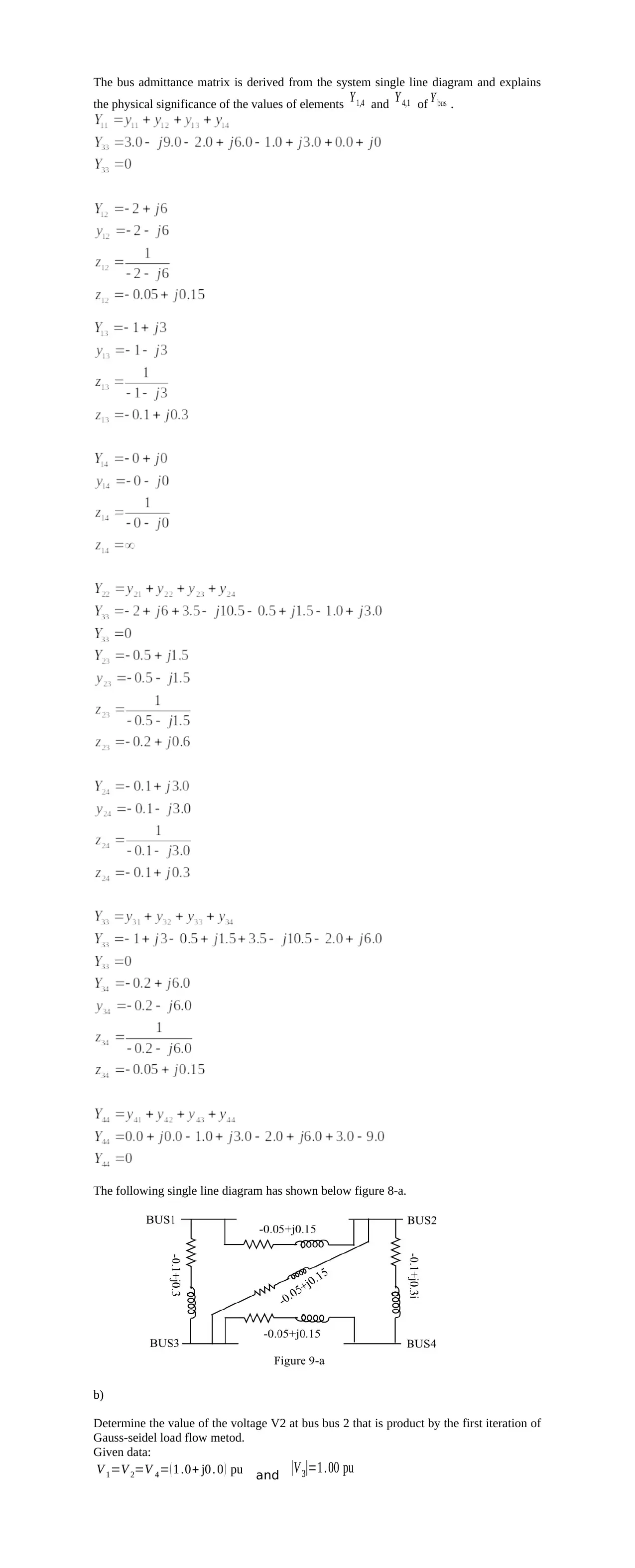
The bus admittance matrix is derived from the system single line diagram and explains
the physical significance of the values of elements Y 1,4 and Y 4,1 of Y bus .
The following single line diagram has shown below figure 8-a.
b)
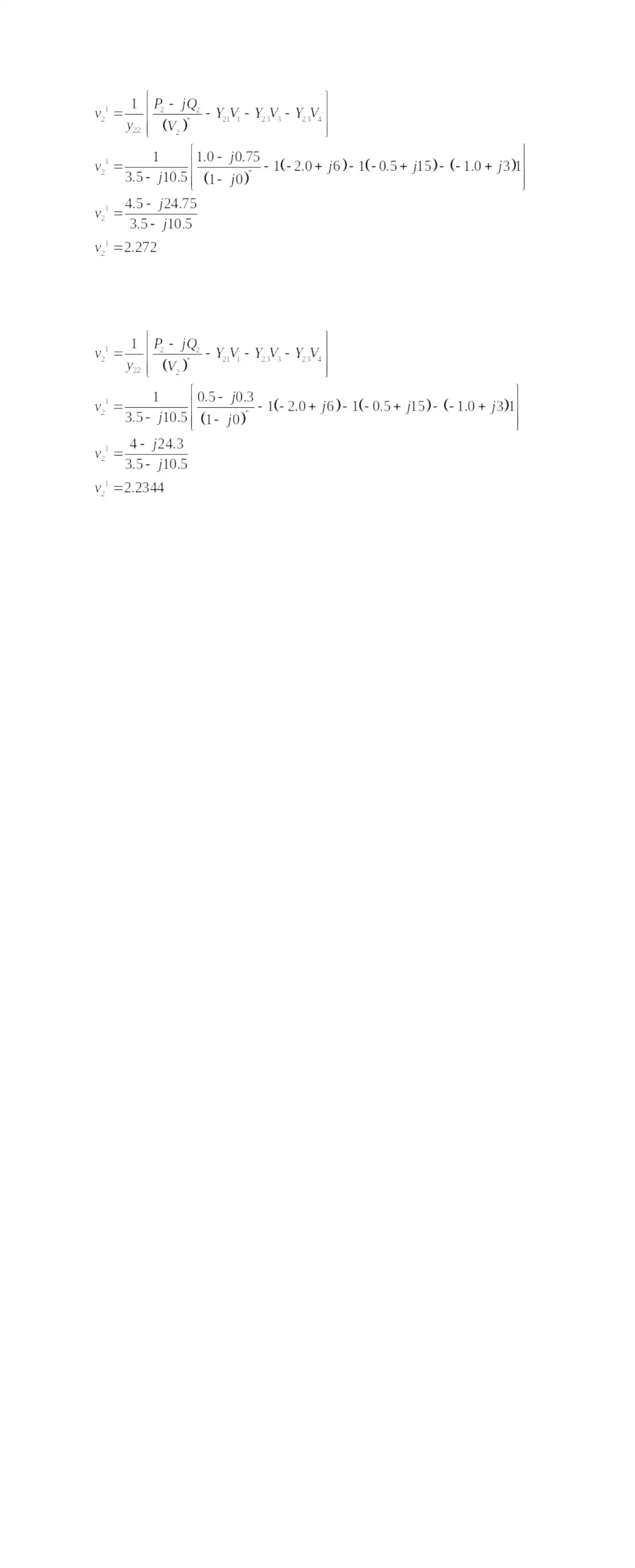
Determine the value of the voltage V2 at bus bus 2 that is product by the first iteration of
Gauss-seidel load flow metod.
Given data:
V 1=V 2=V 4= ( 1 .0+ j0 . 0 ) pu and |V 3|=1 . 00 pu

Secure Best Marks with AI Grader

Need help grading? Try our AI Grader for instant feedback on your assignments.
Document Page
1 out of 11
circle_padding
hide_on_mobile
zoom_out_icon
[object Object]

Your All-in-One AI-Powered Toolkit for Academic Success.

Available 24*7 on WhatsApp / Email

[object Object]