ProductsLogo
LogoStudy Documents
LogoAI Grader
LogoAI Answer
LogoAI Code Checker
LogoPlagiarism Checker
LogoAI Paraphraser
LogoAI Quiz
LogoAI Detector
PricingBlogAbout Us
logo

Tubular Heat Exchanger: Study of Energy Balance and Heat Transfer

Verified

Added on  2023/05/27

|7
|1053
|214
AI Summary
This laboratory experiment aims to study the tubular heat exchanger and its energy balance and heat transfer. The experiment measures the overall heat transfer coefficient in a double pipe heat exchanger under counter-current and co-current flow arrangements, demonstrates how temperature varies with position in the heat exchanger, and investigates the effect of fluid flow-rate on heat transfer coefficients.

Contribute Materials

Your contribution can guide someone’s learning journey. Share your documents today.
Document Page
1
Tubular Heat Exchanger
Tabular Heat Exchanger
First name Last name
Institution

Secure Best Marks with AI Grader

Need help grading? Try our AI Grader for instant feedback on your assignments.
Document Page
2
Tubular Heat Exchanger
Abstract
The main aim of this laboratory experiment is to study the tubular heat exchanger. The
computation of the transfer of heat and loss of heat were determined for the study of energy
balance. The analysis showed that the heat tabular heat exchanger in the co-current flow was
lower as compared to counter current flow.
.
Introduction
The heat exchanger is made up of wall in which the heat flows, the wall that separates the cold
fluid and hot fluid, in the process of exchanging heat at this section there is a loss of heat by the
hot fluid, while there is a gain in the same heat that was loss in hot fluid by the cold fluid. There
is an equilibrium rate at which the heat is gained by the cold fluid and the heat that is loss by the
hot fluid, the equilibrium is also extended to the rate of transferring heat through the exchanger
wall. The heat transfer across the hot fluid and cold fluid can be represented by the following
equations;
Rate of transfer of heat = mass flow – rate * specific heat capacity * change in temperature
˙Q= ( ˙mc P )hot ( Thot ¿T hotout )
Q= ( ˙mc P ) cold ( T coldoutT cold¿ )
The heat transfer across the exchanger wall can be represented as;
Rate of transfer of heat = coefficient of heat transfer * heat transfer area * temperature change of
a driving force.
˙Q=UA T
The value of rate of transfer of heat can also be represented as = temperature change of a driving
force/ total resistance to heat transfer
˙Q= T
Rtotal
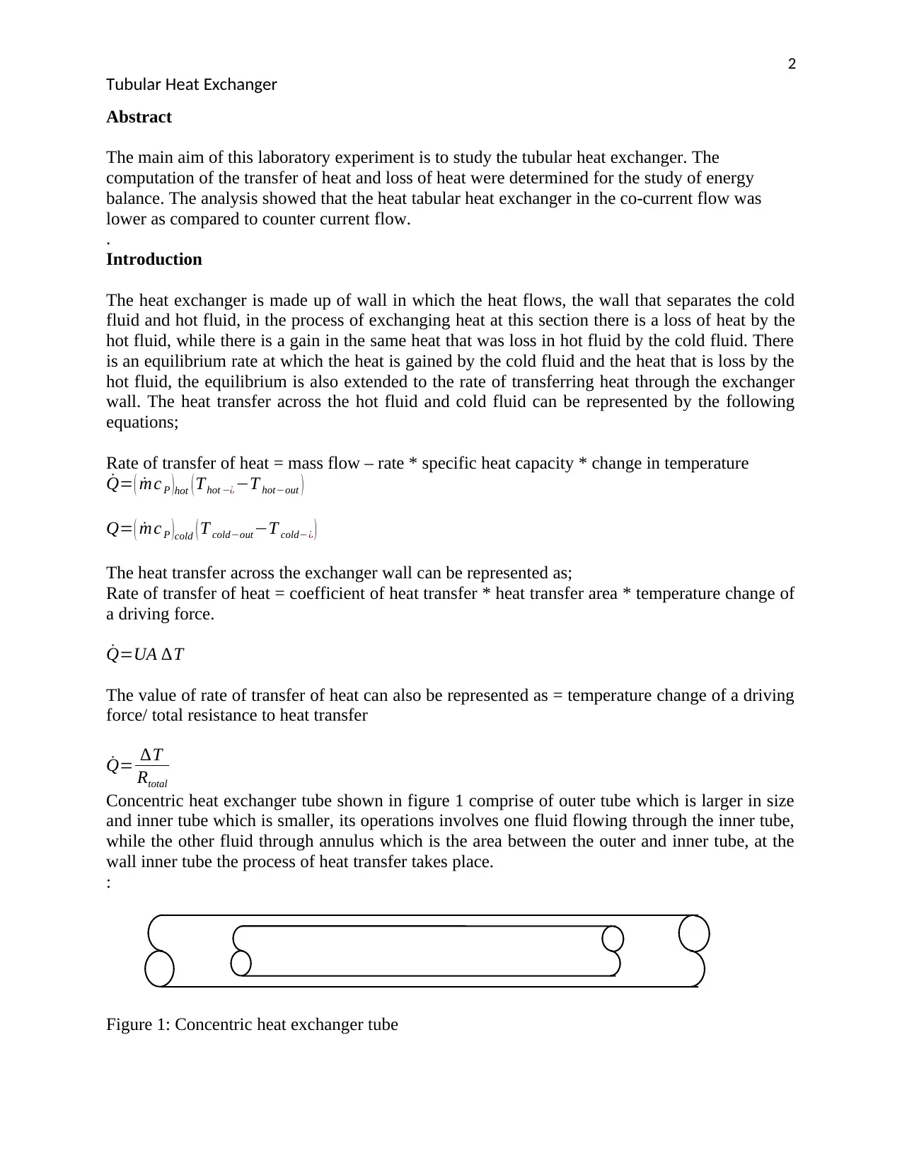
Concentric heat exchanger tube shown in figure 1 comprise of outer tube which is larger in size
and inner tube which is smaller, its operations involves one fluid flowing through the inner tube,
while the other fluid through annulus which is the area between the outer and inner tube, at the
wall inner tube the process of heat transfer takes place.
:
Figure 1: Concentric heat exchanger tube
Document Page
3
Tubular Heat Exchanger
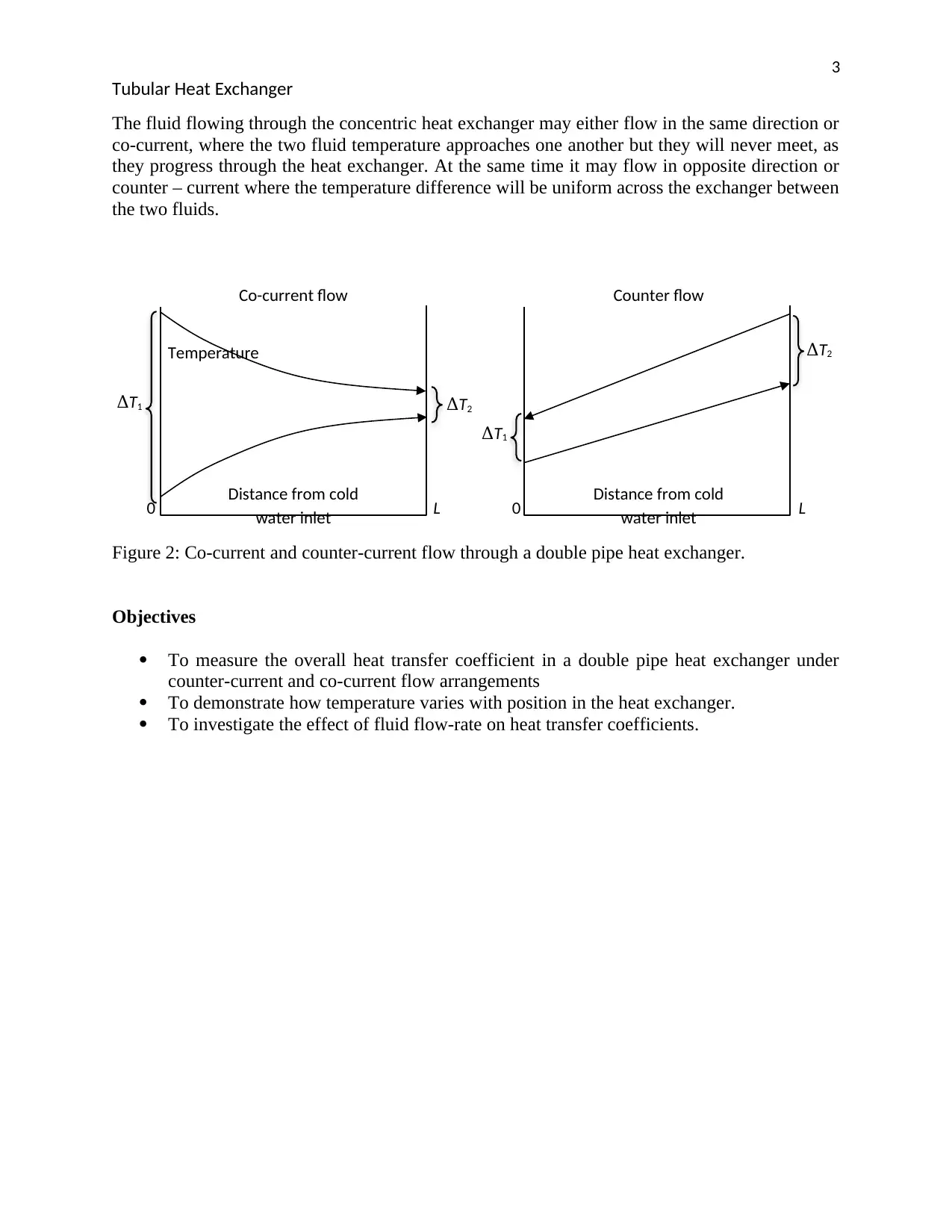
The fluid flowing through the concentric heat exchanger may either flow in the same direction or
co-current, where the two fluid temperature approaches one another but they will never meet, as
they progress through the heat exchanger. At the same time it may flow in opposite direction or
counter – current where the temperature difference will be uniform across the exchanger between
the two fluids.
Figure 2: Co-current and counter-current flow through a double pipe heat exchanger.
Objectives
To measure the overall heat transfer coefficient in a double pipe heat exchanger under
counter-current and co-current flow arrangements
To demonstrate how temperature varies with position in the heat exchanger.
To investigate the effect of fluid flow-rate on heat transfer coefficients.
Distance from cold
water inlet
Temperature
L0 Distance from cold
water inlet L0
Co-current flow Counter flow
ΔT2
ΔT2
ΔT1
ΔT1
Document Page
4
Tubular Heat Exchanger
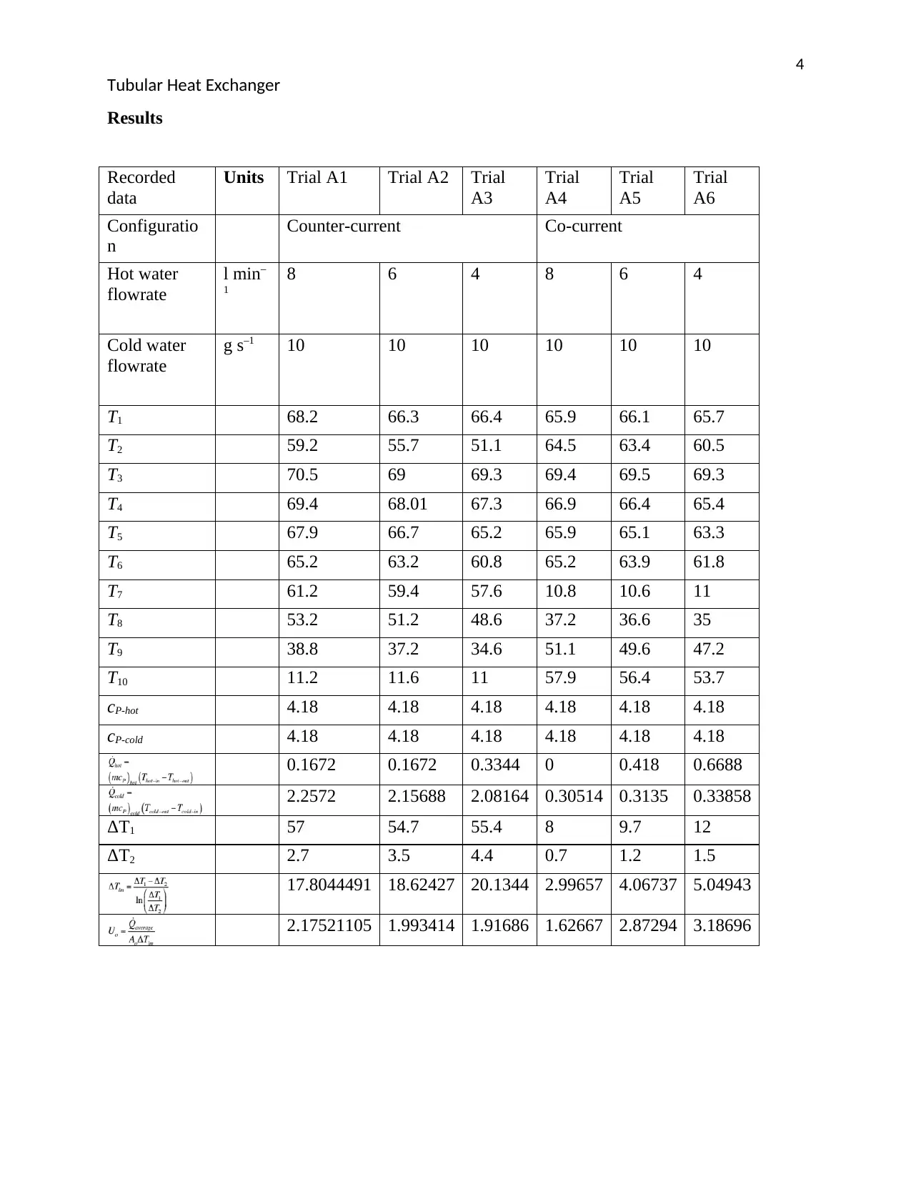
Results
Recorded
data
Units Trial A1 Trial A2 Trial
A3
Trial
A4
Trial
A5
Trial
A6
Configuratio
n
Counter-current Co-current
Hot water
flowrate
l min
1
8 6 4 8 6 4
Cold water
flowrate
g s–1 10 10 10 10 10 10
T1 68.2 66.3 66.4 65.9 66.1 65.7
T2 59.2 55.7 51.1 64.5 63.4 60.5
T3 70.5 69 69.3 69.4 69.5 69.3
T4 69.4 68.01 67.3 66.9 66.4 65.4
T5 67.9 66.7 65.2 65.9 65.1 63.3
T6 65.2 63.2 60.8 65.2 63.9 61.8
T7 61.2 59.4 57.6 10.8 10.6 11
T8 53.2 51.2 48.6 37.2 36.6 35
T9 38.8 37.2 34.6 51.1 49.6 47.2
T10 11.2 11.6 11 57.9 56.4 53.7
cP-hot 4.18 4.18 4.18 4.18 4.18 4.18
cP-cold 4.18 4.18 4.18 4.18 4.18 4.18
0.1672 0.1672 0.3344 0 0.418 0.6688
2.2572 2.15688 2.08164 0.30514 0.3135 0.33858
ΔT1 57 54.7 55.4 8 9.7 12
ΔT2 2.7 3.5 4.4 0.7 1.2 1.5
17.8044491 18.62427 20.1344 2.99657 4.06737 5.04943
2.17521105 1.993414 1.91686 1.62667 2.87294 3.18696

Paraphrase This Document

Need a fresh take? Get an instant paraphrase of this document with our AI Paraphraser
Document Page
5
Tubular Heat Exchanger
Discussions
3.5 4 4.5 5 5.5 6 6.5 7 7.5 8 8.5
62
63
64
65
66
67
68
69
70
71
flow rate
Temperature
58
59
60
61
62
63
64
65
66
Flow rate
Temperature
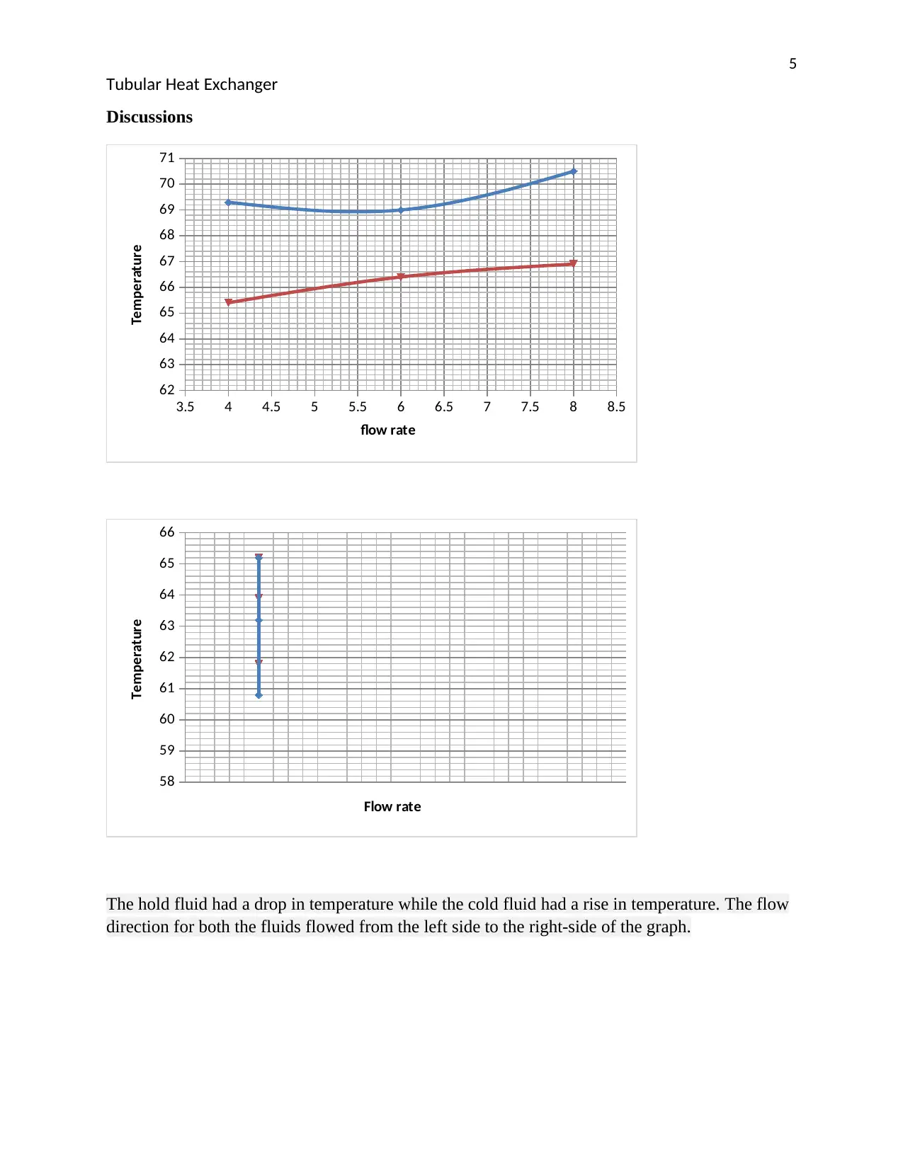
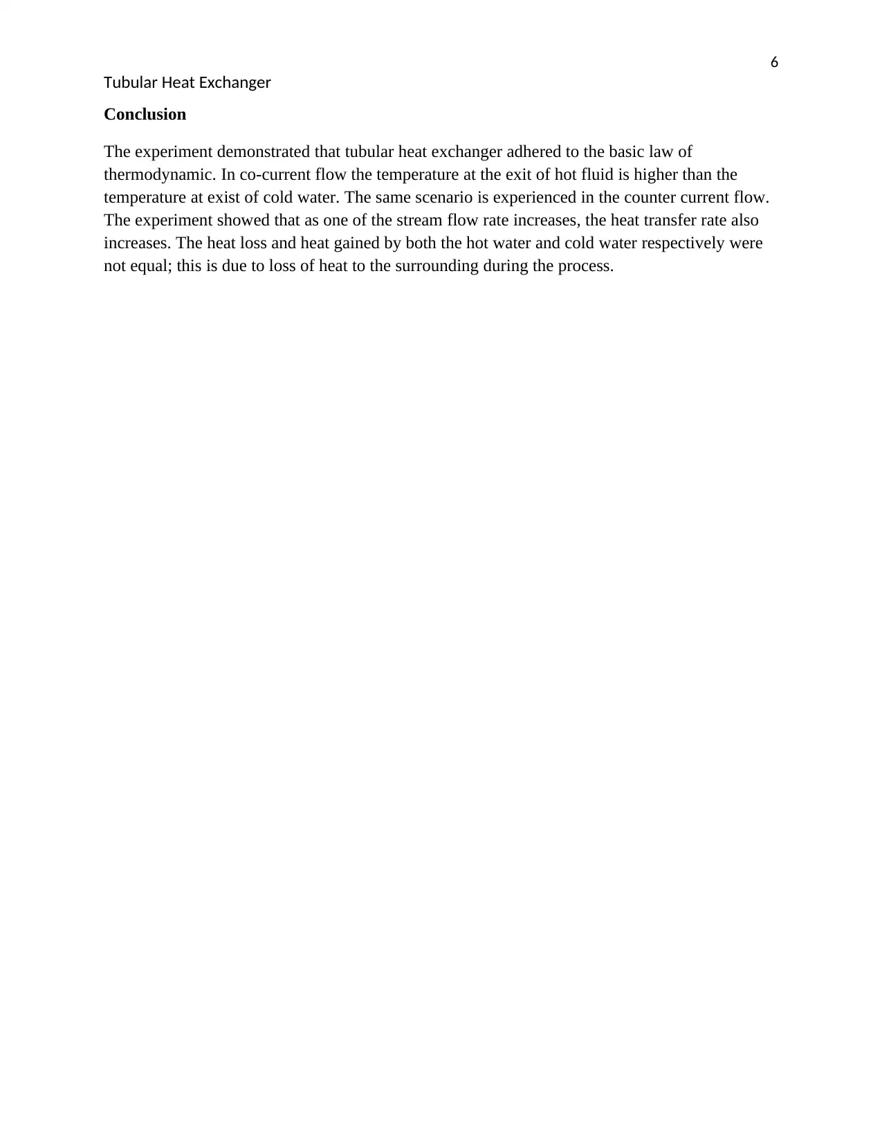
The hold fluid had a drop in temperature while the cold fluid had a rise in temperature. The flow
direction for both the fluids flowed from the left side to the right-side of the graph.
Document Page
6
Tubular Heat Exchanger
Conclusion
The experiment demonstrated that tubular heat exchanger adhered to the basic law of
thermodynamic. In co-current flow the temperature at the exit of hot fluid is higher than the
temperature at exist of cold water. The same scenario is experienced in the counter current flow.
The experiment showed that as one of the stream flow rate increases, the heat transfer rate also
increases. The heat loss and heat gained by both the hot water and cold water respectively were
not equal; this is due to loss of heat to the surrounding during the process.
Document Page
7
Tubular Heat Exchanger
References
Agyenim, F., Eames, P., & Smyth, M. (2009). A comparison of heat transfer enhancement in a
medium temperature thermal energy storage heat exchanger using fins. Solar
Energy, 83(9), 1509-1520.
Demir, H., Koyun, A., & Temir, G. (2009). Heat transfer of horizontal parallel pipe ground heat
exchanger and experimental verification. Applied thermal engineering, 29(2-3), 224-233.
Salimpour, M. R. (2009). Heat transfer coefficients of shell and coiled tube heat
exchangers. Experimental thermal and fluid science, 33(2), 203-207.
Wang, S., Wen, J., & Li, Y. (2009). An experimental investigation of heat transfer enhancement
for a shell-and-tube heat exchanger. Applied Thermal Engineering, 29(11-12), 2433-
2438.
1 out of 7
[object Object]

Your All-in-One AI-Powered Toolkit for Academic Success.

Available 24*7 on WhatsApp / Email

[object Object]