ProductsLogo
LogoStudy Documents
LogoAI Grader
LogoAI Answer
LogoAI Code Checker
LogoPlagiarism Checker
LogoAI Paraphraser
LogoAI Quiz
LogoAI Detector
PricingBlogAbout Us
logo

Vehicle Suspension System Analysis Assignment | Desklib

Verified

Added on  2023/06/03

|10
|1655
|429
AI Summary
This text provides a detailed analysis of vehicle suspension system with solved assignments, essays, and dissertations. It covers topics such as block diagram, free body diagram, state space analysis, and more. The suspension parameters, natural resonance, damping ratio, and characteristic equation are also discussed.

Contribute Materials

Your contribution can guide someone’s learning journey. Share your documents today.
Document Page
SIGNALS & SYSTEMS
VEHICLE SUSPENSION SYSTEM ANALYSIS
ASSIGNMENT
STUDENT NAME
STUDENT ID NUMBER
INSTITUTIONAL AFFILIATION
LOCATION (STATE, COUNTRY)
DATE OF SUBMISSION

Secure Best Marks with AI Grader

Need help grading? Try our AI Grader for instant feedback on your assignments.
Document Page
SECTION 1 (25 Marks)
Block diagram of the vehicle suspension system
SECTION I
Part 1
The free body diagram of the single mass spring damper system,
Document Page
Part 2
Motion of the system is described by the linear constant-coefficient differential equation
For a second order differential system,
meq ¨y ( t ) Ceq ( ˙x ( t ) ˙y ( t ) ) keq ( x ( t ) y ( t ) ) =0
meq ¨y ( t ) +Ceq ˙y ( t ) +k eq y ( t )=Ceq ˙x ( t ) +k eq x ( t )
Dividing through by Meq,
¨y ( t ) + Ceq
meq
˙y ( t ) + k eq
meq
y ( t )= Ceq
meq
˙x ( t )+ k eq
meq
x ( t )
Part 3
Find H(s) using the Laplace transform,
¨y ( t ) + Ceq
meq
˙y ( t ) + k eq
meq
y ( t ) = Ceq
meq
˙x ( t ) + k eq
meq
x ( t )
Assuming zero initial conditions
s2 Y ( s ) + Ceq
meq
sY ( s ) + keq
meq
Y ( s ) = Ceq
meq
sX ( s ) + keq
meq
X (s )
(s2 + Ceq
meq
s+ keq
meq )Y ( s )= ( Ceq
meq
s+ keq
meq ) X ( s )
To find H(s) as a transfer function,
H ( s ) = X ( s )
Y ( s )
Document Page
H ( s )=
( Ceq
meq
s+ keq
meq )
(s2+ Ceq
meq
s+ k eq
meq )
For a damped system, the homogenous second order DE is given as,
d2 y ( t )
d t2 +2 ζ ωn
dy ( t )
dt + ωn
2 y ( t ) =0
Part 4
2 ζ ωn =Ceq
meq
ωn
2= keq
meq
ωn = keq
meq
undamped natural resonant frequency
ζ =
1
2 ωn
Ceq
meq
= Ceq
2 meq ωn
Replacing the values in the above equation,
ζ = Ceq
2meq ( keq
meq ) damping ratio
Part 5
The characteristic equation is given as,
s2 + Ceq
meq
s+ keq
meq
=0
Part 6
d2 y ( t )
d t2 +2 ζ ωn
dy ( t )
dt + ωn
2 y ( t ) =0

Paraphrase This Document

Need a fresh take? Get an instant paraphrase of this document with our AI Paraphraser
Document Page
ζ =0,
d2 y ( t )
d t2 +ωn
2 y ( t )=0
¨y +61.765 y=0
ζ =1,
d2 y ( t )
d t2 +2 ωn
dy ( t )
dt + ωn
2 y ( t ) =0
¨y +15.72 ˙y+ 61.765 y =0
ζ >1,
d2 y ( t )
d t2 +2 ζ ωn
dy ( t )
dt + ωn
2 y ( t ) =0
¨y +15.72 ζ ˙y+ 61.765 y =0
Part 7
Suspension parameters
meq =340 kg
k eq=21,000 N /m
Given these two values, one can find the natural resonance,
ωn= k eq
meq
= 21000
340 =7.859 rad
s
d2 y ( t )
d t2 +15.72 ζ dy ( t )
dt +61.765 y ( t ) =0
¨y +15.72 ζ ˙y+ 61.765 y =0
Document Page
ωn=2 π f n
f n= ωn
2 π = 7.859
2 π =11.921 Hz
Part 8
The value of Cs given ζ =1,
Ceq
2meq ωn
=1
Ceq=2meq ωn
Ceq=2( 340 kg )( 7.859 rad
s )
Ceq=5344.12 N . m/ s
SECTION III (25marks)
The state space analysis enables a system be represented using matrix differential equation.
The state equation
˙q= Aq+Bx
The output equation
y=Cq+ Dx
d
dt {
x
.
x }= [ 0 1
k
m
c
m ] {
x
.
x }+ {0
1 }(f /m)
A=
[ 0 1
k
m
c
m ]
B= {0
1 }
U =f /m
Document Page
D=0
For the output state variables,
y= [1 0 ] [ x1
x2 ]+ [ 0 ] u
C= [ 1 0 ]
State space analysis
A system is defined using a transfer function of the ratio between the output and the input. The
physical systems are analyzed based on the nth order of the ordinary differential equations. The
characteristic equation forms the basis of the state equation and the output equation (Kisi.deu,
2016). The use of state space models identifies the state variables which eliminate the algebraic
equations in other modeling forms. The result is expressed as a set of two differential equations
based on the nth order of the differential equation. For the linear systems, the equations are
obtained in matrix forms (Piconepress, 2012). The state variables determine the future behavior
of the system and the system excitation signals are given as the set of the state variables such as,
[ x1 ( t ) x2 ( t ) xn ( t ) ]
It avoids redundancy in the system analysis by using the least number of state variables. One key
example is the RLC circuit.
E1= 1
2 L iL
2 , E2= 1
2 C ( ic dt ) 2
=1
2 C vc
2
ic=C d vc
dt =u ( t ) iL

Secure Best Marks with AI Grader

Need help grading? Try our AI Grader for instant feedback on your assignments.
Document Page
L d iL
dt =RiL+vc
v0=R iL( t)
The column matrix is developed with state variables and the state vector is given as,
From the vector notation using the state differential equation and the output equation,
˙x= Ax+ Bu
y=Cx + Du
˙x=
[ 0 1
C
1
L
R
L ] x +
[ 1
C
0 ]u ( t )
y= [ 0 R ] x
˙x1=a11 x1+a12 x2 + a1n xn +b11 u1+b1 m um
˙x2=a21 x1+a22 x2+ a2 n xn+b21 u1+b2 m um

˙xn=an1 x1+ an 2 x2 + ann xn +bn 1 u1+bnm um
d
dt [ x1
x2

xn
]=
[ a11 a12 a1 n
a21 a22 a2 n

an 1 an2 ann
] [ x1
x2

xn
] +
[ b11 b1 m

bn 1 bnm ] [ u1

um ]
x=
[ x1
x2

xn
]
X ( s )= x( 0 )
sa + b
sa U ( s )
s X ( s )x0=a X ( s )+b U ( s )
Document Page
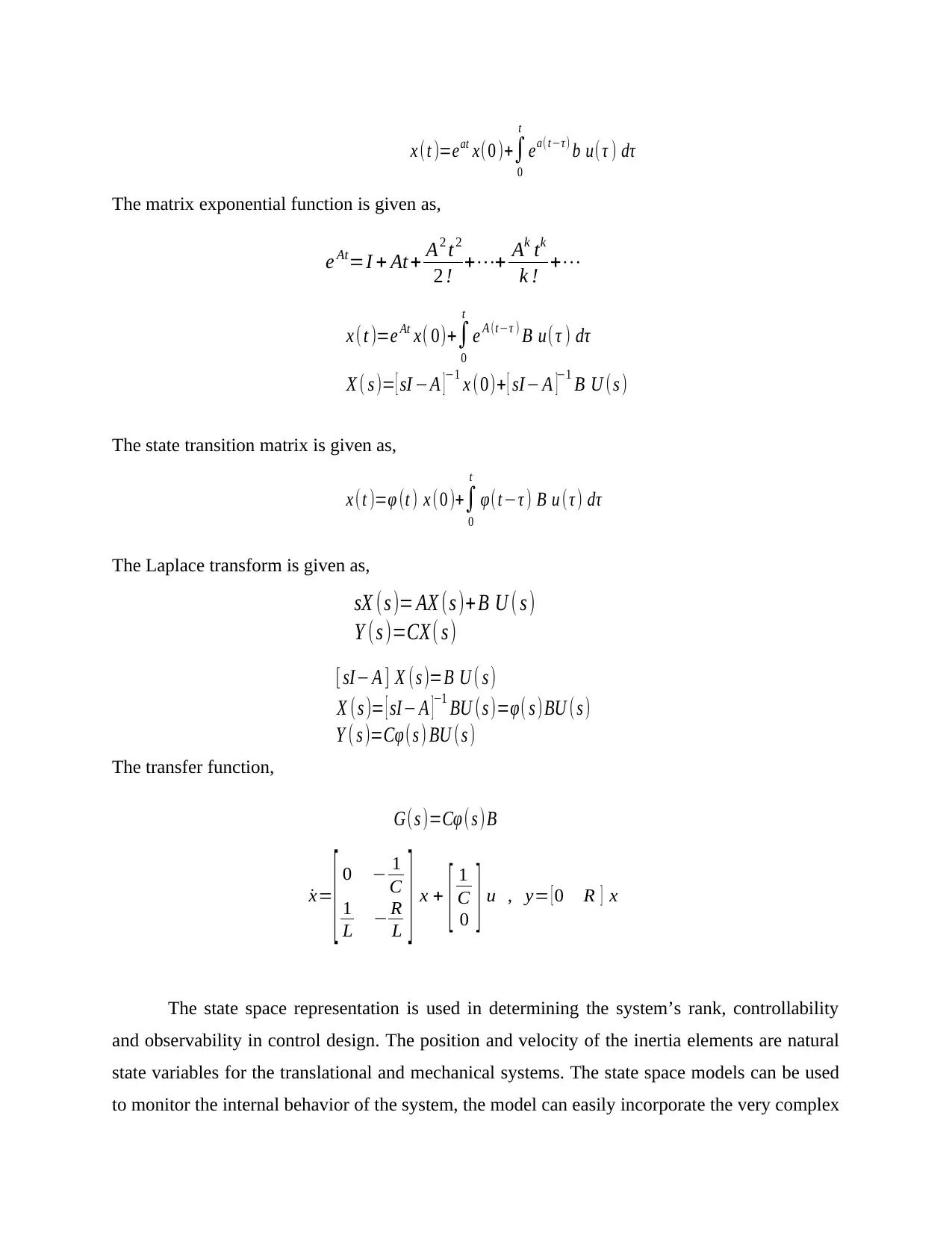
The matrix exponential function is given as,
The state transition matrix is given as,
The Laplace transform is given as,
The transfer function,
The state space representation is used in determining the system’s rank, controllability
and observability in control design. The position and velocity of the inertia elements are natural
state variables for the translational and mechanical systems. The state space models can be used
to monitor the internal behavior of the system, the model can easily incorporate the very complex
x ( t )=eat x(0 )+
0
t
ea( tτ) b u( τ )
e At=I + At + A2 t2
2 ! ++ Ak tk
k ! +
x ( t )=e At x( 0)+
0
t
e A (tτ ) B u( τ )
X ( s )= [ sI A ]1 x (0)+ [ sI A ]1 B U (s )
x ( t )=φ (t ) x ( 0 )+
0
t
φ( tτ ) B u ( τ )
sX (s )= AX (s )+ B U ( s )
Y ( s )=CX( s )
[ sI A ] X ( s )=B U ( s )
X ( s )= [ sI A ]
1 BU (s )=φ( s )BU ( s )
Y ( s )=( s ) BU ( s )
G( s )= ( s )B
˙x=
[ 0 1
C
1
L R
L ] x + [ 1
C
0 ] u , y= [ 0 R ] x
Document Page
output variables as well as having significant computation merits for the computer simulation
(Utexas, Ece, 2015). The model is used in representing the multi-input and multi-output linear
and non-linear systems.
REFERENCES
Kisi.deu. (2016). State Variable Models. Retrieved from Non-linear Model Systems:
kisi.deu.edu.tr/userweb/zeki.kiral/NONLINEAR.../NLC_State_Variable_Model.ppt
Piconepress. (2012). State Variables are defined as: Differential equations. Retrieved from State
Space: https://www.isip.piconepress.com/courses/temple/ece_3512/lectures/.../
lecture_38.ppt
Utexas, Ece. (2015). State-space analysis of control systems. Retrieved from State variable
Approach: https://users.ece.utexas.edu/~buckman/Svars1.pdf
1 out of 10
[object Object]

Your All-in-One AI-Powered Toolkit for Academic Success.

Available 24*7 on WhatsApp / Email

[object Object]