Banking Software Project Report
VerifiedAdded on 2019/09/26
|28
|6017
|505
Project
AI Summary
This project report documents the development of a banking software application for NatioNarrow Building Society. The report includes a detailed explanation of the software's design, using UML diagrams such as use case, class, and sequence diagrams. The Java source code for the application is provided, along with a comprehensive discussion of the Software Development Life Cycle (SDLC) followed. The SDLC stages covered include requirement gathering, design, development, software testing (unit, integration, system, and acceptance testing), deployment, and feedback. The report also addresses professional, legal, social, security, and ethical issues related to software development and use within an organizational context. The conclusion highlights the software's ability to meet customer, bank teller, and bank manager needs, emphasizing its high quality and error-free nature due to rigorous testing.

1
Paraphrase This Document
Need a fresh take? Get an instant paraphrase of this document with our AI Paraphraser
Contents
1.Use Case Model Diagram (Logical Design Diagram)..................................................................4
2.Class Diagram (Logical Design)..................................................................................................6
3.Sequence Diagram (Logical Design)............................................................................................8
4. Program........................................................................................................................................9
Critical Discussion: Introduction...................................................................................................18
NationNarrow Reflection and Critical-Evaluation....................................................................18
Critical self-reflection on the work................................................................................................19
Software Development Life Cycle (SDLC) of this software.....................................................19
Requirement Gathering..........................................................................................................19
Design.....................................................................................................................................19
Development..........................................................................................................................20
Software Testing.....................................................................................................................20
Deployment............................................................................................................................21
Feedback.................................................................................................................................22
Issues..............................................................................................................................................23
Conclusion.....................................................................................................................................23
References......................................................................................................................................24
2
Table of Content
S. NO. CONTENT PAGE NO.
1. Use Case Model Diagram 2
2. Class Diagram 4
3. Sequence Diagram 6
4. Program 8
5. Critical Discussion : Introduction 16
6. Critical self-reflection on the work 17
7. Issues 21
8. Conclusion 21
9. References 22
3
S. NO. CONTENT PAGE NO.
1. Use Case Model Diagram 2
2. Class Diagram 4
3. Sequence Diagram 6
4. Program 8
5. Critical Discussion : Introduction 16
6. Critical self-reflection on the work 17
7. Issues 21
8. Conclusion 21
9. References 22
3
⊘ This is a preview!⊘
Do you want full access?
Subscribe today to unlock all pages.
Trusted by 1+ million students worldwide
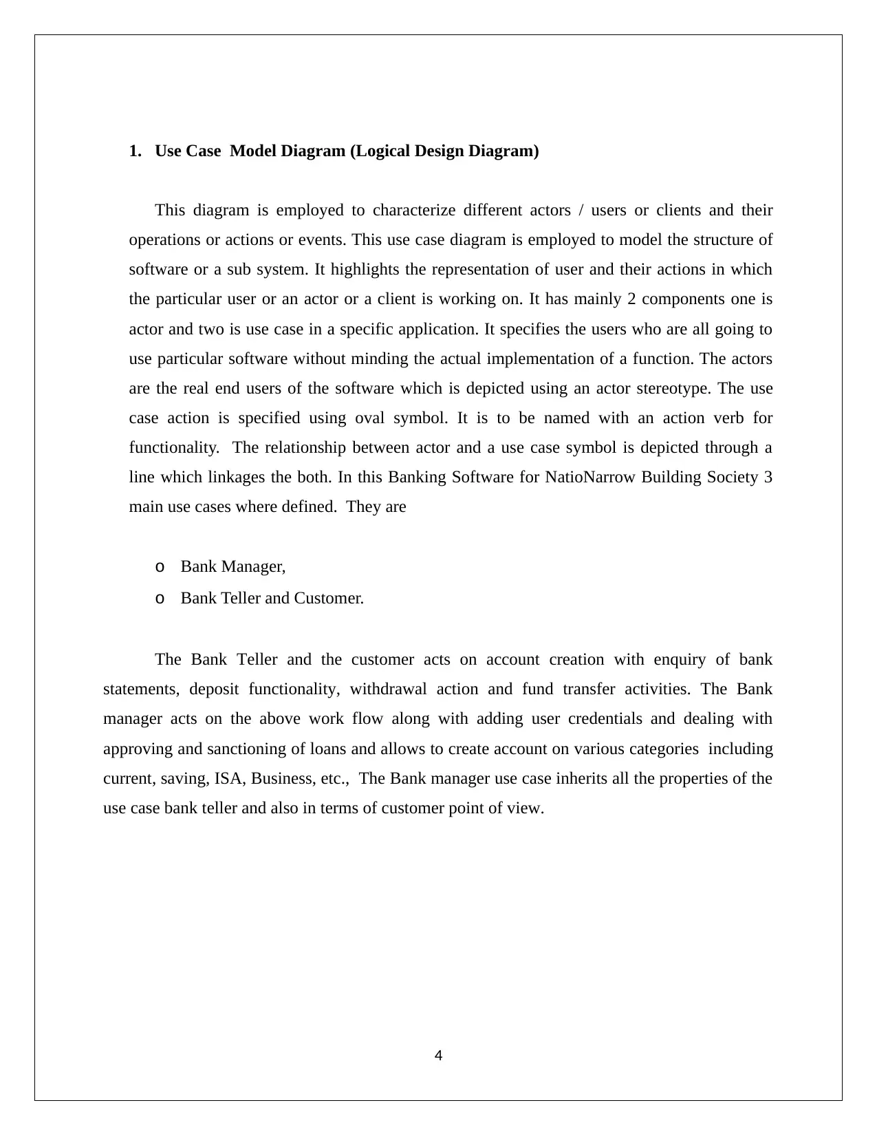
1. Use Case Model Diagram (Logical Design Diagram)
This diagram is employed to characterize different actors / users or clients and their
operations or actions or events. This use case diagram is employed to model the structure of
software or a sub system. It highlights the representation of user and their actions in which
the particular user or an actor or a client is working on. It has mainly 2 components one is
actor and two is use case in a specific application. It specifies the users who are all going to
use particular software without minding the actual implementation of a function. The actors
are the real end users of the software which is depicted using an actor stereotype. The use
case action is specified using oval symbol. It is to be named with an action verb for
functionality. The relationship between actor and a use case symbol is depicted through a
line which linkages the both. In this Banking Software for NatioNarrow Building Society 3
main use cases where defined. They are
o Bank Manager,
o Bank Teller and Customer.
The Bank Teller and the customer acts on account creation with enquiry of bank
statements, deposit functionality, withdrawal action and fund transfer activities. The Bank
manager acts on the above work flow along with adding user credentials and dealing with
approving and sanctioning of loans and allows to create account on various categories including
current, saving, ISA, Business, etc., The Bank manager use case inherits all the properties of the
use case bank teller and also in terms of customer point of view.
4
Paraphrase This Document
Need a fresh take? Get an instant paraphrase of this document with our AI Paraphraser
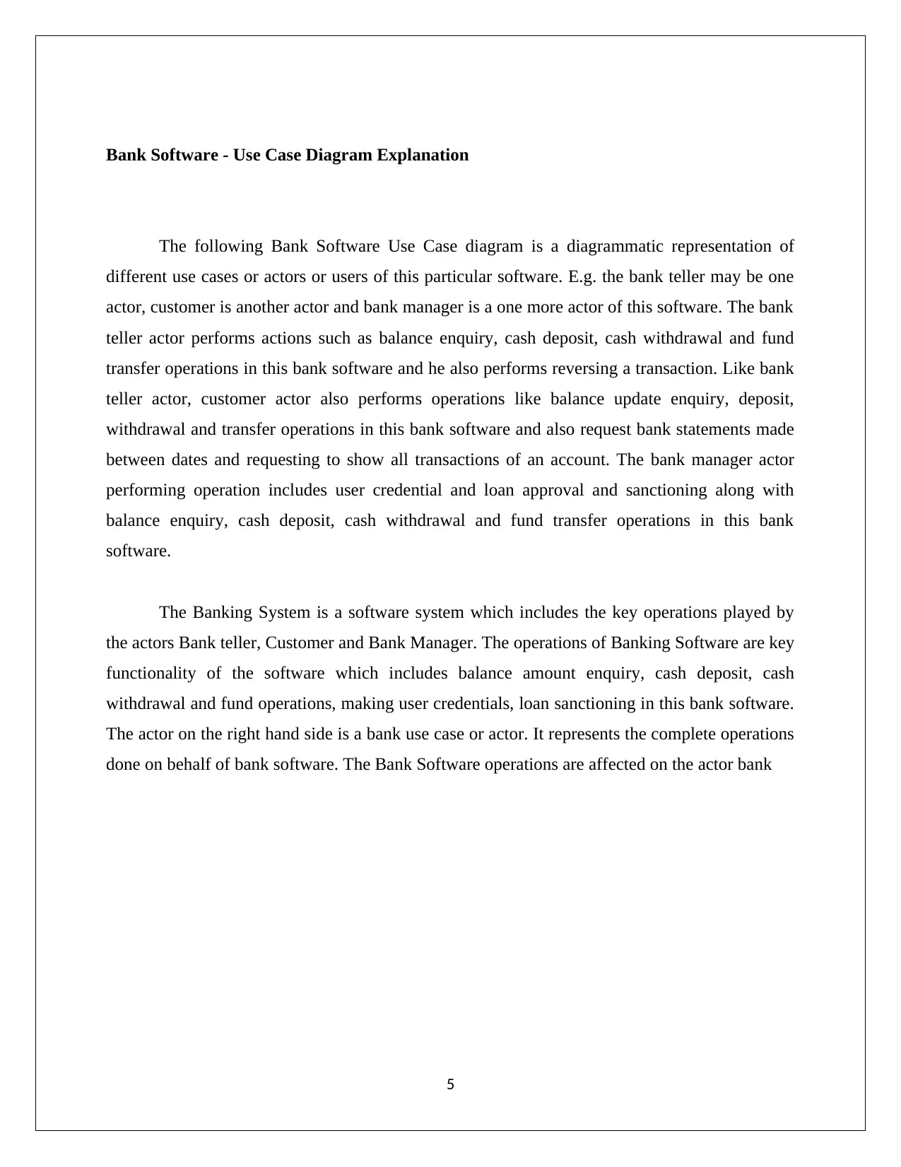
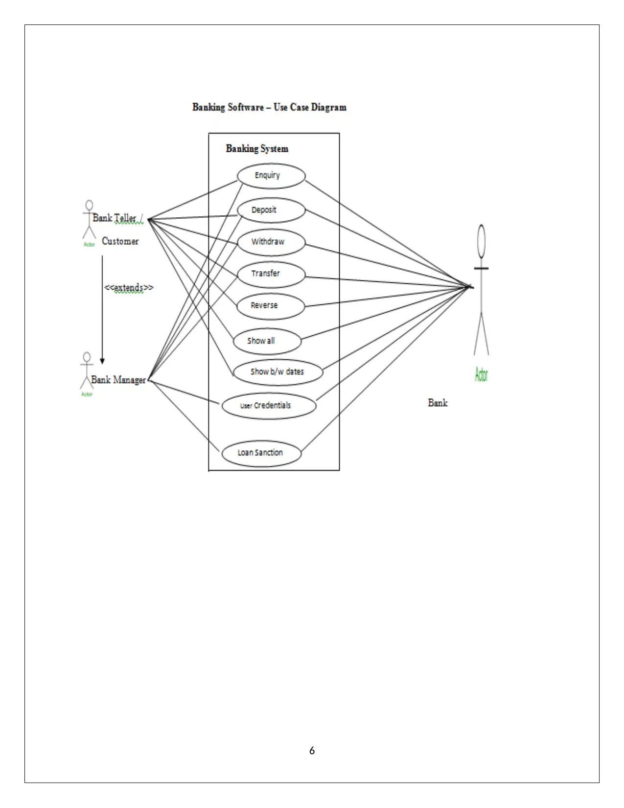
Bank Software - Use Case Diagram Explanation
The following Bank Software Use Case diagram is a diagrammatic representation of
different use cases or actors or users of this particular software. E.g. the bank teller may be one
actor, customer is another actor and bank manager is a one more actor of this software. The bank
teller actor performs actions such as balance enquiry, cash deposit, cash withdrawal and fund
transfer operations in this bank software and he also performs reversing a transaction. Like bank
teller actor, customer actor also performs operations like balance update enquiry, deposit,
withdrawal and transfer operations in this bank software and also request bank statements made
between dates and requesting to show all transactions of an account. The bank manager actor
performing operation includes user credential and loan approval and sanctioning along with
balance enquiry, cash deposit, cash withdrawal and fund transfer operations in this bank
software.
The Banking System is a software system which includes the key operations played by
the actors Bank teller, Customer and Bank Manager. The operations of Banking Software are key
functionality of the software which includes balance amount enquiry, cash deposit, cash
withdrawal and fund operations, making user credentials, loan sanctioning in this bank software.
The actor on the right hand side is a bank use case or actor. It represents the complete operations
done on behalf of bank software. The Bank Software operations are affected on the actor bank
5
6
⊘ This is a preview!⊘
Do you want full access?
Subscribe today to unlock all pages.
Trusted by 1+ million students worldwide
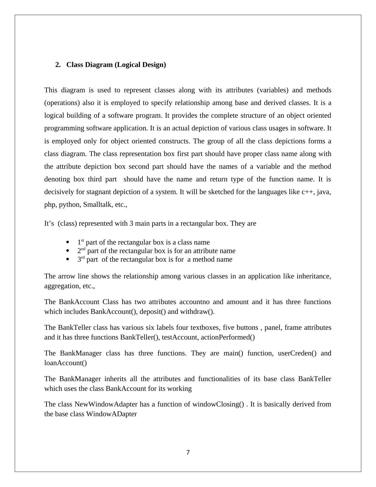
2. Class Diagram (Logical Design)
This diagram is used to represent classes along with its attributes (variables) and methods
(operations) also it is employed to specify relationship among base and derived classes. It is a
logical building of a software program. It provides the complete structure of an object oriented
programming software application. It is an actual depiction of various class usages in software. It
is employed only for object oriented constructs. The group of all the class depictions forms a
class diagram. The class representation box first part should have proper class name along with
the attribute depiction box second part should have the names of a variable and the method
denoting box third part should have the name and return type of the function name. It is
decisively for stagnant depiction of a system. It will be sketched for the languages like c++, java,
php, python, Smalltalk, etc.,
It’s (class) represented with 3 main parts in a rectangular box. They are
1st part of the rectangular box is a class name
2nd part of the rectangular box is for an attribute name
3rd part of the rectangular box is for a method name
The arrow line shows the relationship among various classes in an application like inheritance,
aggregation, etc.,
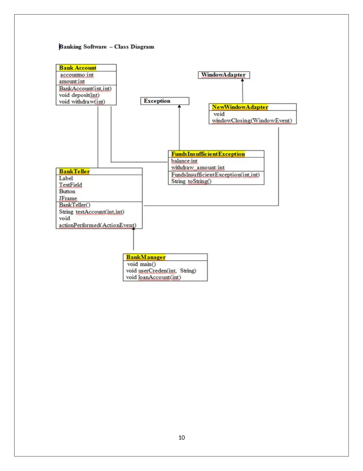
The BankAccount Class has two attributes accountno and amount and it has three functions
which includes BankAccount(), deposit() and withdraw().
The BankTeller class has various six labels four textboxes, five buttons , panel, frame attributes
and it has three functions BankTeller(), testAccount, actionPerformed()
The BankManager class has three functions. They are main() function, userCreden() and
loanAccount()
The BankManager inherits all the attributes and functionalities of its base class BankTeller
which uses the class BankAccount for its working
The class NewWindowAdapter has a function of windowClosing() . It is basically derived from
the base class WindowADapter
7
This diagram is used to represent classes along with its attributes (variables) and methods
(operations) also it is employed to specify relationship among base and derived classes. It is a
logical building of a software program. It provides the complete structure of an object oriented
programming software application. It is an actual depiction of various class usages in software. It
is employed only for object oriented constructs. The group of all the class depictions forms a
class diagram. The class representation box first part should have proper class name along with
the attribute depiction box second part should have the names of a variable and the method
denoting box third part should have the name and return type of the function name. It is
decisively for stagnant depiction of a system. It will be sketched for the languages like c++, java,
php, python, Smalltalk, etc.,
It’s (class) represented with 3 main parts in a rectangular box. They are
1st part of the rectangular box is a class name
2nd part of the rectangular box is for an attribute name
3rd part of the rectangular box is for a method name
The arrow line shows the relationship among various classes in an application like inheritance,
aggregation, etc.,
The BankAccount Class has two attributes accountno and amount and it has three functions
which includes BankAccount(), deposit() and withdraw().
The BankTeller class has various six labels four textboxes, five buttons , panel, frame attributes
and it has three functions BankTeller(), testAccount, actionPerformed()
The BankManager class has three functions. They are main() function, userCreden() and
loanAccount()
The BankManager inherits all the attributes and functionalities of its base class BankTeller
which uses the class BankAccount for its working
The class NewWindowAdapter has a function of windowClosing() . It is basically derived from
the base class WindowADapter
7
Paraphrase This Document
Need a fresh take? Get an instant paraphrase of this document with our AI Paraphraser

The class FundsInsufficientException has two attributes namely balance and withdraw _amount
and two functions namely FundsInsufficientException() and toString(). It is basically derived
from the base class Exception
8
and two functions namely FundsInsufficientException() and toString(). It is basically derived
from the base class Exception
8
Bank- Software - Class Diagram Explanation
In the following Bank software class diagram it is represented with many classes and its
mutual relationship existing among those classes. The class diagram has totally seven classes,
out of seven classes; two classes are built in classes imported from a java packages and the
remaining five classes are user defined classes. The yellow color highlighted classes are user
defined required classes in the Bank Software. The Bank Account classes are used to perform
main bank operations including deposit and withdraw which is inherited by the class Bank
Teller. The Bank Teller class is added with the function testAccount() along with the base class
bankaccount properties which is again inherited by the class BankManager which supports
functionality like usercredential() and loanaccount() along with the properties of its base class
Bank Teller.
The user defined class FundSufficientException is inherited from the built in class
Exception which support to raise a user defined exception fundsufficientexception in case of
accessing insufficient amount. The one more user defined class NewWindowAdapter is inherited
from the built in class WindowAdapter which support for handling windows in the bank software
9
⊘ This is a preview!⊘
Do you want full access?
Subscribe today to unlock all pages.
Trusted by 1+ million students worldwide
10
Paraphrase This Document
Need a fresh take? Get an instant paraphrase of this document with our AI Paraphraser
Sequence Diagram (Logical Design)
It illustrates dealings among objects in a chronological order. It is also termed as event
diagram or event scenarios. It showcases when one object finishes it operations and when
another begins its work. It is for the depiction of factual time state of affairs. It shows the manner
how a system is moving on while it’s functioning. The symbols employed to draw basically the
sequence diagram involves an actor, life lines, messages, etc., The Actor is an external entity
which is employed to play a role on a system functioning. It is placed at the top of the line .Any
number of actors can be involved in a scenario depending upon the system. Each instance of a
class is depicted as a life line which is also placed at the top of a line. It is a name represented
component of a sequence diagram. The life line is an internal component of a sequence diagram.
The messages are depicted using an arrow line which shows the contact between objects or
among an instance of a class or an object. Messages and lifeline are the vital components for the
depiction of a sequence diagram. In the below diagram Bank actor is involved along with the life
lines which has an instance of the classes AccountCreation , BankManager and Loan. Initially
BankAccount is activated then a testAccount is communicated followed by show details deposit
withdrawal messages are communicated to the instance of a class BankManager. During
withdrawal in case of insufficient balance exception is raised it is sent back to the actor Bank. It
is also the duty of the bank to approve and sanction a loan to the customers. The Loan Account
Creation is communicated to the instance of a class named loan then Loan Approval is also
communicated to the instance of a class Loan. In case of not approval of a loan account by the
credential it is sent back to an actor Bank. It all shows the sequential movements of various
messages from an actor to an instance of a class or from an instance of a class to an another
instance of a class
11
Banking Software – Sequential Diagram Explanation
In the following Banking Software - sequential diagram is explored. It is a diagram which
shows the sequential actions flows in the banking software. In the diagram actor bank and
instances of classes are involved.
The actor is Bank which is involved along with the life lines which is actually an instance of
the classes existing in the Bank software which includes AccountCreation, BankManager and
Loan. Initially instance of BankAccount is activated toward the Account creation then a
testAccount is communicated towards the BankManager Instance followed by show details
deposit withdrawal messages are communicated to the instance of a class BankManager. During
withdrawal in case of insufficient balance exception is raised it is sent back to the actor Bank
from the instance BankManager. It is also the duty of the bank to approve and sanction a loan to
the customers for which a message is communicated from the Bank to the instance of a class
Loan with the actions LoanaccountCreation and LoanSanction. In case of not approving the loan
a message is communicated from the instance of Loan to the actor Bank
12
⊘ This is a preview!⊘
Do you want full access?
Subscribe today to unlock all pages.
Trusted by 1+ million students worldwide
1 out of 28
Related Documents


Your All-in-One AI-Powered Toolkit for Academic Success.
+13062052269
info@desklib.com
Available 24*7 on WhatsApp / Email
![[object Object]](/_next/static/media/star-bottom.7253800d.svg)
Unlock your academic potential
Copyright © 2020–2026 A2Z Services. All Rights Reserved. Developed and managed by ZUCOL.