BN106: Networking Fundamentals Local Area Network Design Report
VerifiedAdded on 2020/02/19
|7
|1112
|154
Report
AI Summary
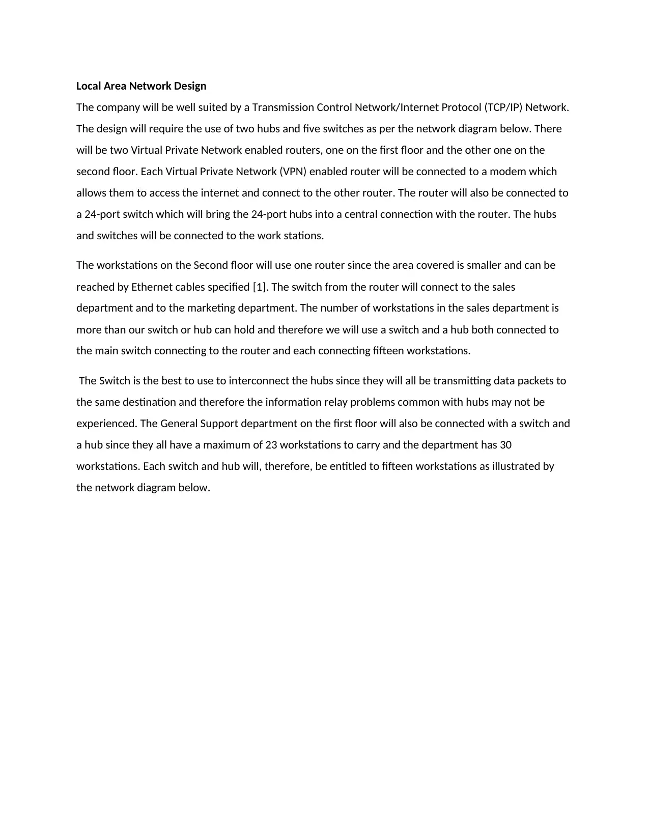
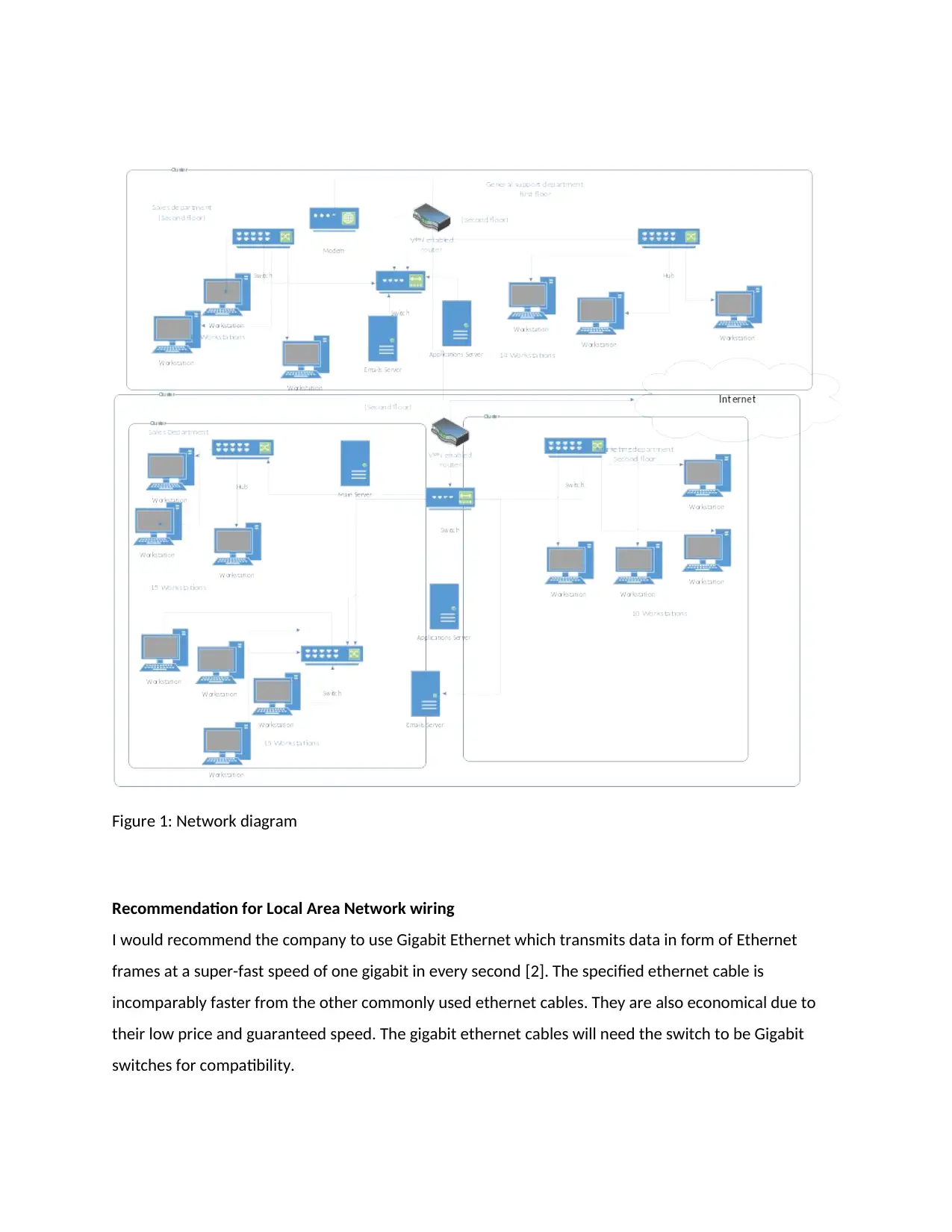
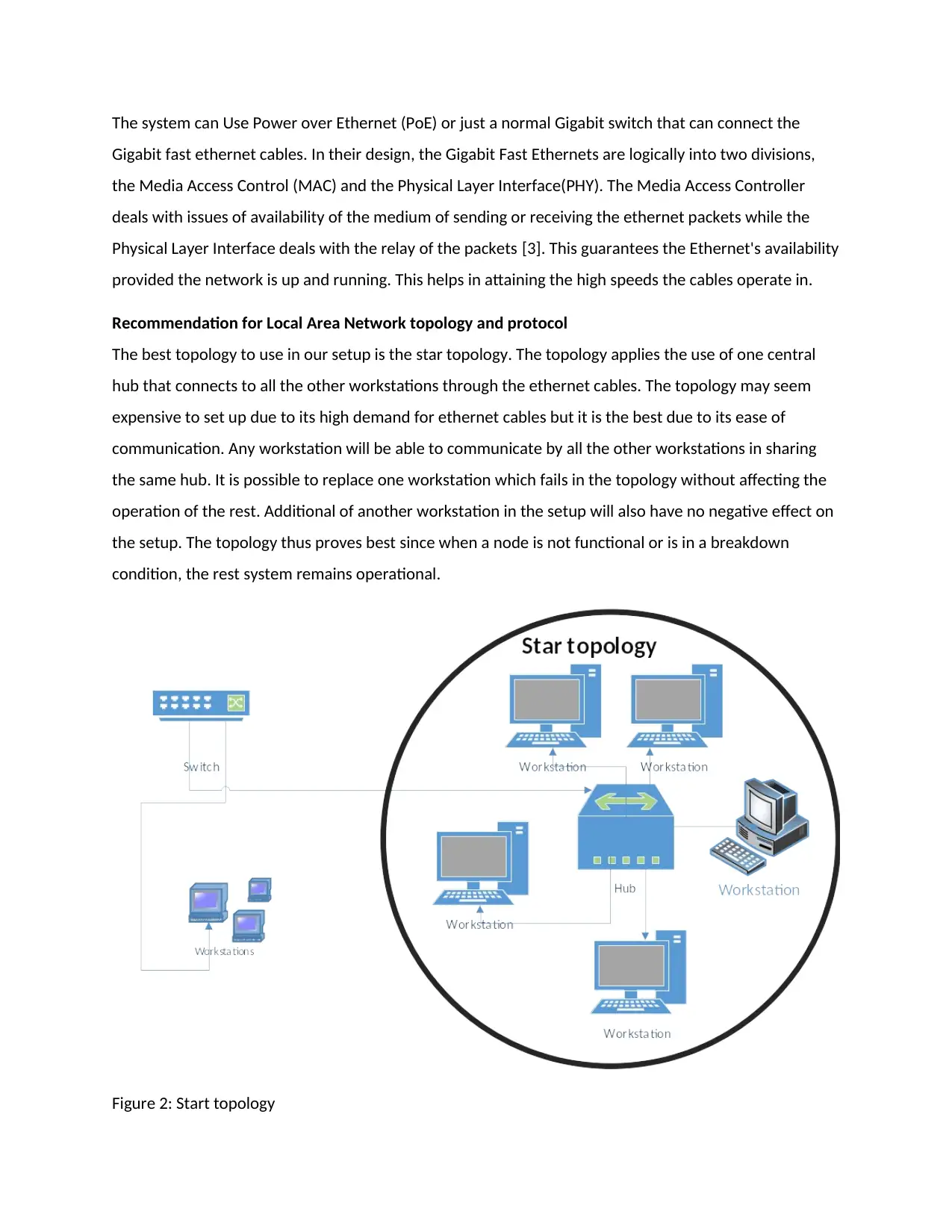
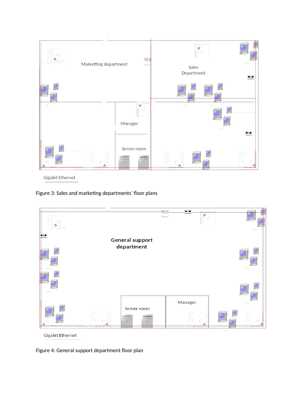
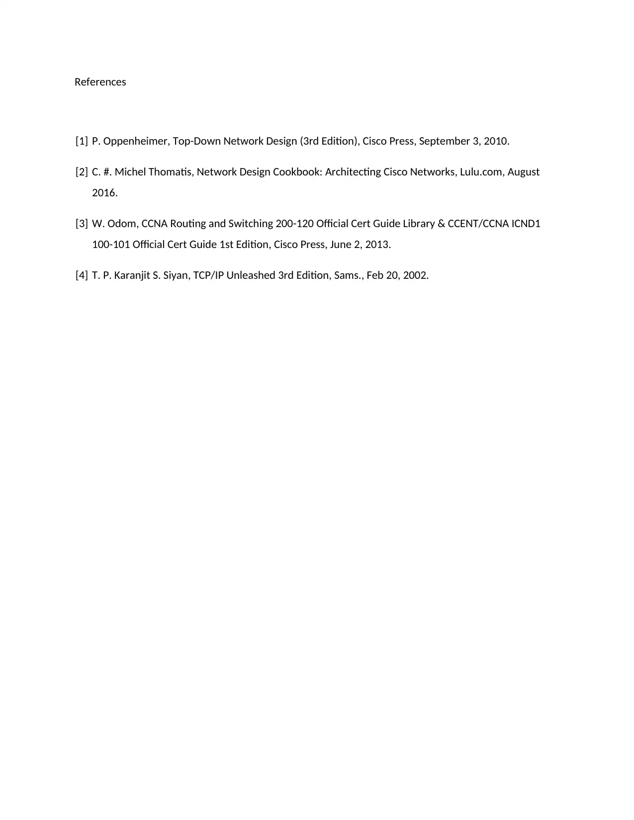
This report presents a comprehensive local area network (LAN) design for a company, focusing on the application of networking fundamentals. The design utilizes a Transmission Control Protocol/Internet Protocol (TCP/IP) network, incorporating two virtual private network (VPN) enabled routers, modems, 24-port switches, hubs, and switches to connect workstations across two floors. The report recommends Gigabit Ethernet for high-speed data transmission and a star topology for ease of communication and network management. Furthermore, it advocates for the use of the TCP/IP protocol for its simplicity in design, maintenance, and troubleshooting, ensuring compatibility across different hardware and operating systems. Floor plans for the sales, marketing, and general support departments are also included, detailing the placement of workstations and server rooms. The document provides a practical application of networking concepts, offering insights into network design and implementation, making it a valuable resource for students studying networking fundamentals.

BN106
Networking Fundamentals
Network models, media, and connections
Networking Fundamentals
Network models, media, and connections
Paraphrase This Document
Need a fresh take? Get an instant paraphrase of this document with our AI Paraphraser

Local Area Network Design
The company will be well suited by a Transmission Control Network/Internet Protocol (TCP/IP) Network.
The design will require the use of two hubs and five switches as per the network diagram below. There
will be two Virtual Private Network enabled routers, one on the first floor and the other one on the
second floor. Each Virtual Private Network (VPN) enabled router will be connected to a modem which
allows them to access the internet and connect to the other router. The router will also be connected to
a 24-port switch which will bring the 24-port hubs into a central connection with the router. The hubs
and switches will be connected to the work stations.
The workstations on the Second floor will use one router since the area covered is smaller and can be
reached by Ethernet cables specified [1]. The switch from the router will connect to the sales
department and to the marketing department. The number of workstations in the sales department is
more than our switch or hub can hold and therefore we will use a switch and a hub both connected to
the main switch connecting to the router and each connecting fifteen workstations.
The Switch is the best to use to interconnect the hubs since they will all be transmitting data packets to
the same destination and therefore the information relay problems common with hubs may not be
experienced. The General Support department on the first floor will also be connected with a switch and
a hub since they all have a maximum of 23 workstations to carry and the department has 30
workstations. Each switch and hub will, therefore, be entitled to fifteen workstations as illustrated by
the network diagram below.

Figure 1: Network diagram
Recommendation for Local Area Network wiring
I would recommend the company to use Gigabit Ethernet which transmits data in form of Ethernet
frames at a super-fast speed of one gigabit in every second [2]. The specified ethernet cable is
incomparably faster from the other commonly used ethernet cables. They are also economical due to
their low price and guaranteed speed. The gigabit ethernet cables will need the switch to be Gigabit
switches for compatibility.
⊘ This is a preview!⊘
Do you want full access?
Subscribe today to unlock all pages.

Trusted by 1+ million students worldwide

The system can Use Power over Ethernet (PoE) or just a normal Gigabit switch that can connect the
Gigabit fast ethernet cables. In their design, the Gigabit Fast Ethernets are logically into two divisions,
the Media Access Control (MAC) and the Physical Layer Interface(PHY). The Media Access Controller
deals with issues of availability of the medium of sending or receiving the ethernet packets while the
Physical Layer Interface deals with the relay of the packets [3]. This guarantees the Ethernet's availability
provided the network is up and running. This helps in attaining the high speeds the cables operate in.
Recommendation for Local Area Network topology and protocol
The best topology to use in our setup is the star topology. The topology applies the use of one central
hub that connects to all the other workstations through the ethernet cables. The topology may seem
expensive to set up due to its high demand for ethernet cables but it is the best due to its ease of
communication. Any workstation will be able to communicate by all the other workstations in sharing
the same hub. It is possible to replace one workstation which fails in the topology without affecting the
operation of the rest. Additional of another workstation in the setup will also have no negative effect on
the setup. The topology thus proves best since when a node is not functional or is in a breakdown
condition, the rest system remains operational.
Figure 2: Start topology
Paraphrase This Document
Need a fresh take? Get an instant paraphrase of this document with our AI Paraphraser

It would be better to use the TCP/IP protocol to the great simplification it has in the design,
maintenance and troubleshooting the network system. When using TCP/IP, it is easy to detect any error
that occurs in the Network system and correct it compared to other protocols [1]. The network will,
therefore, be easy to use and understand even for those with no networking experience.
The network protocol also makes it easy to upgrade the network if need be may be in future. It is
common for network systems to be upgraded as companies continue to grow. It would be beneficial,
therefore, if the network was designed in a way that during upgrading, only new workstations and
devices will be added in the network system. Other protocols may not have room for expansion. In our
design, it is possible to add eight extra machines in any router of the sales department without
tampering with the already configured devices all the speed of access of data.
Using TCP/IP ensures connection and communication in the networked devices regardless of their
hardware systems. The use of Internet Protocol (IP address) ensures compatibility of all the networked
devices with no regard to systems capabilities or Operating system e.g., a windows workstation can be
connected to the switch together with a Linux workstation and both will communicate and function
properly which is also a benefit.
Floor plan
The marketing department is smaller in terms of workstations since it only has ten workstations. It will,
therefore, be suitable to hold the server room and all other workstations will be connected from here.
The Sales department has thirty workstations which will be split into two, one using a hub and the other
to use a switch.

Figure 3: Sales and marketing departments’ floor plans
Figure 4: General support department floor plan
⊘ This is a preview!⊘
Do you want full access?
Subscribe today to unlock all pages.

Trusted by 1+ million students worldwide

References
[1] P. Oppenheimer, Top-Down Network Design (3rd Edition), Cisco Press, September 3, 2010.
[2] C. #. Michel Thomatis, Network Design Cookbook: Architecting Cisco Networks, Lulu.com, August
2016.
[3] W. Odom, CCNA Routing and Switching 200-120 Official Cert Guide Library & CCENT/CCNA ICND1
100-101 Official Cert Guide 1st Edition, Cisco Press, June 2, 2013.
[4] T. P. Karanjit S. Siyan, TCP/IP Unleashed 3rd Edition, Sams., Feb 20, 2002.
1 out of 7
Related Documents

Your All-in-One AI-Powered Toolkit for Academic Success.
+13062052269
info@desklib.com
Available 24*7 on WhatsApp / Email
Unlock your academic potential
© 2024 | Zucol Services PVT LTD | All rights reserved.