Control and Instrumentation: System Modeling, Analysis, and Control

Verified

Added on  2020/01/28

|53
|3958
|272
Practical Assignment
AI Summary
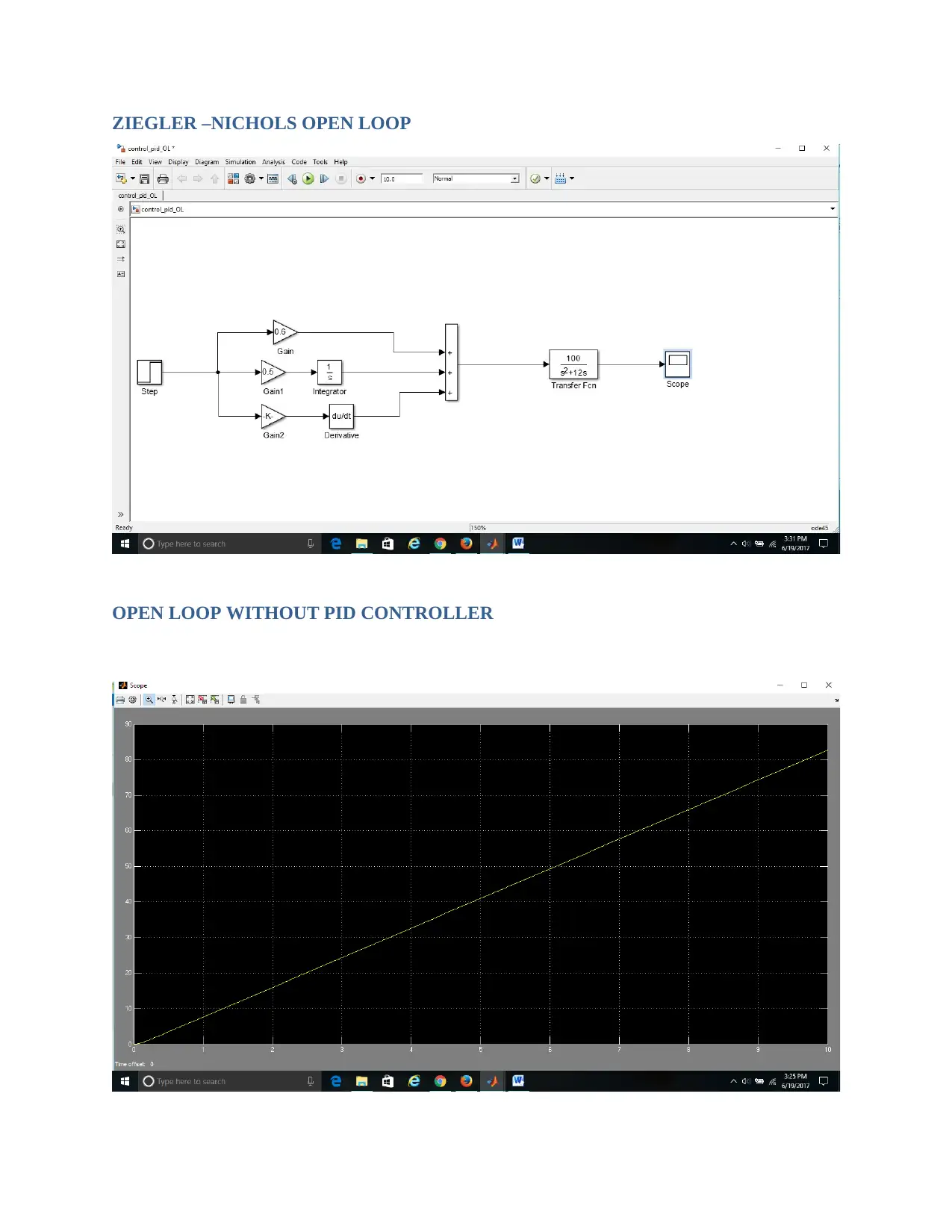
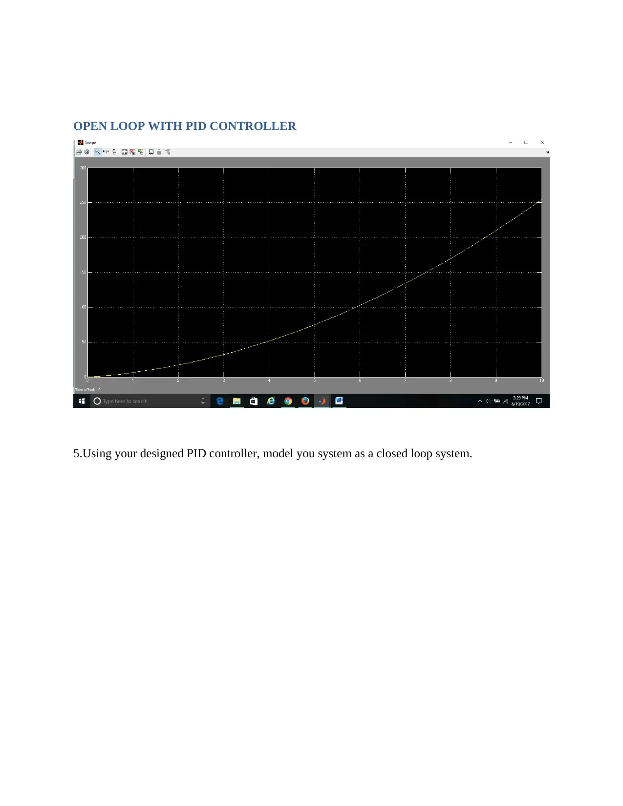
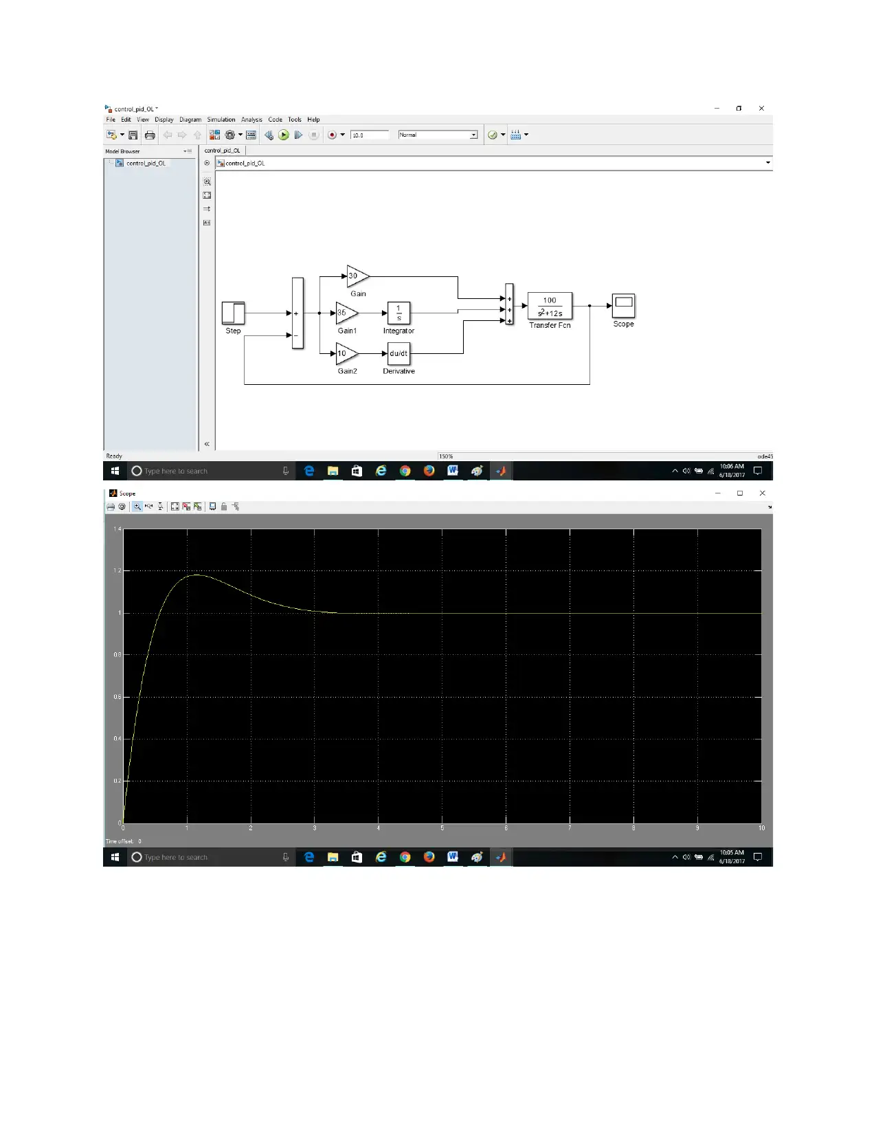
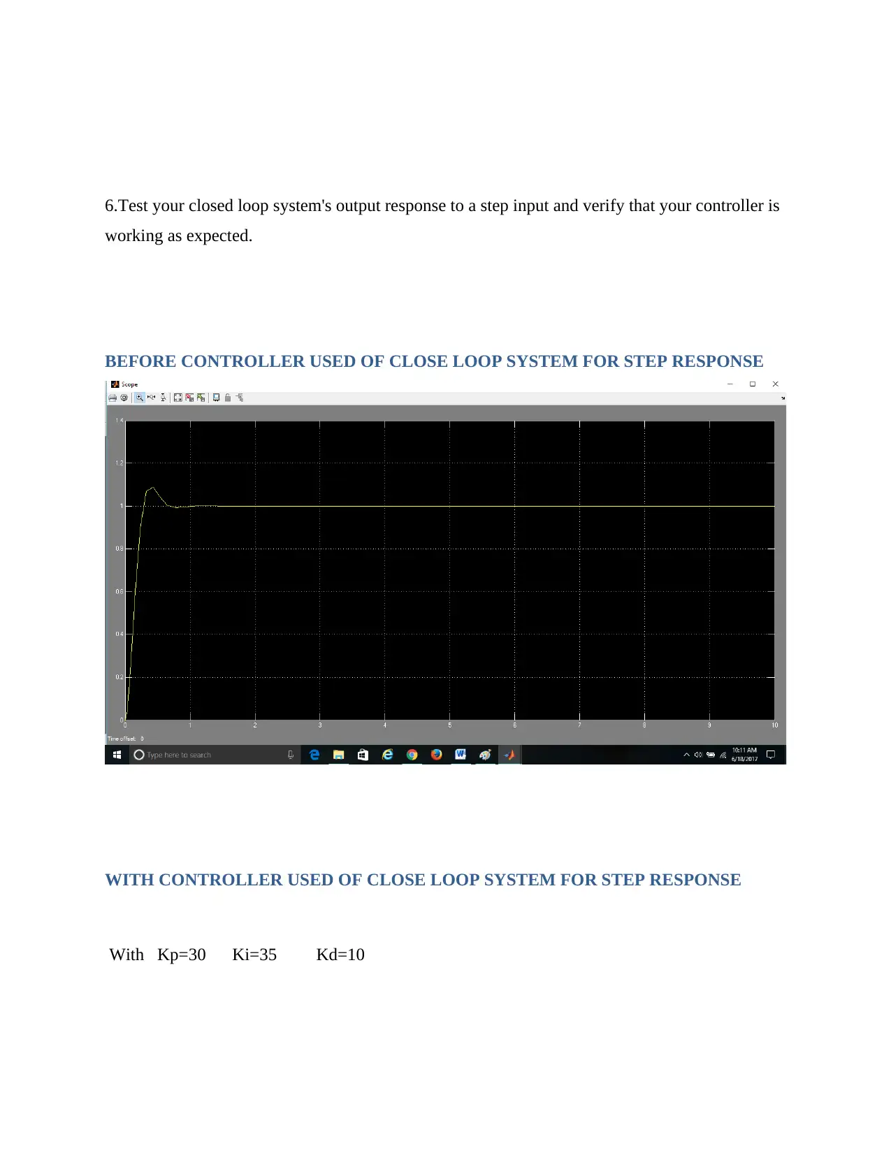
This assignment delves into the principles of control and instrumentation, covering both open and closed-loop systems. The solution begins with obtaining and analyzing step response data from a second-order, linear time-invariant (LTI) open-loop system, followed by the creation of a block diagram and a detailed explanation of its operation. The system is then modeled in MATLAB and Simulink, with the output response to a step input accurately mimicking the real system. PID controllers are designed using the Ziegler-Nichols open-loop (process reaction) method, and the system is modeled as a closed-loop system. The closed-loop system's output response to a step input is tested and verified. Furthermore, the expected frequency response of the open-loop system is calculated, considering low and high frequencies, poles, zeros, and dB frequency. The Simulink model is used to simulate the system and obtain output frequency data in the form of Bode and Nyquist plots. The Simulink results are compared with the calculated results, critically evaluating the model's accuracy. Part B extends the analysis, employing root locus methods for PID controller design and providing comparative analysis of the Ziegler-Nichols and root locus methods. The assignment includes MATLAB code, Simulink models, and graphical representations to illustrate the concepts and results.
Document Page
Control and
Instrumentation
tabler-icon-diamond-filled.svg

Paraphrase This Document

Need a fresh take? Get an instant paraphrase of this document with our AI Paraphraser
Document Page
PART A
1.Obtain the step response timed output data from an instrument, linear and time invariant open
loop control system.
Sol: Linear and time invariant (LTI) system of 2nd order is as
T/F= C(S)/R(S)
= WO2/S2 + 2ƐWnS +Wn2 ( C.L.T.F)
T/F= C(S) / R(S) (O.L.T.F)
=WO2/S2 + 2ƐWnS
Let Wn=10 and Ɛ= 0.6
then, O.L.T.F will be
C(S)/R(S)= T/F = 102/S2 + 2 * 0.6 * 10
=100/S2 +12S
For step response r(t)=1 or R(s)= 1/s
so, C(S)= R(S)100/S2+12S
C(S)=1/S * 100/S2 +12S
C(S)= 100/S3 + 12S2
Matlab code
clear all;
clc;
Document Page
syms s
Gn = [100];
Gd = [1 12 0];
G = tf (Gn,Gd)
step(G);
grid on;
graph
Step Response
Time (seconds)
Amplitude
0 5 10 15 20 25 30 35
0
50
100
150
200
250
300
2.Draw a block diagram of the measured system and describe its operation.
Document Page
Sol:
1) Primary sensing element: which senses the quantity under measurement
2) Plant: It is physical quantity or system whose tranfer function is used for calculation of
system.
3) Variable convension element: which modified suitably output of the primary sensing
element.
4) Variable manipulation element: manipulated signal preserving original nature
5) Data transmission system: which transmit the signal.
6) Data storage element: which stores the data.
7) Data presenting system: present the measured physical quantity in human readable form
to the observer.
tabler-icon-diamond-filled.svg

Paraphrase This Document

Need a fresh take? Get an instant paraphrase of this document with our AI Paraphraser
Document Page
Plant[G(s)]= Wn2/S2+2ƐWn(S)
Here plant is physical system whose transfer functions can calculated using mathematical
expression of it.
Feedback path [H(s)]=1 ; Generally feedback path=1
Document Page
Input= C(s) Plant=physical system
Error=e(t) C(s)=output
proportional= Kp e(t) H(s)=feedback path
Integral= Ki ∫ e(T)dT
Derivative= Kd de(T)/dt
3.Model this system on Matlab or Simulink and test that the output's response to a step input
accurately mimics your real system.
Document Page
0 0.1 0.2 0.3 0.4 0.5 0.6 0.7 0.8
0
1
2
3
4
5
6
7
8
9
Step Response
Time (seconds)
Amplitude
tabler-icon-diamond-filled.svg

Paraphrase This Document

Need a fresh take? Get an instant paraphrase of this document with our AI Paraphraser
Document Page
GRAPH
4. Using Ziegler-Nichols open loop (process reaction) method, design a PID controller for your
model.
Document Page
ZIEGLER –NICHOLS OPEN LOOP
OPEN LOOP WITHOUT PID CONTROLLER
Document Page
OPEN LOOP WITH PID CONTROLLER
5.Using your designed PID controller, model you system as a closed loop system.
tabler-icon-diamond-filled.svg

Paraphrase This Document

Need a fresh take? Get an instant paraphrase of this document with our AI Paraphraser
Document Page
Document Page
6.Test your closed loop system's output response to a step input and verify that your controller is
working as expected.
BEFORE CONTROLLER USED OF CLOSE LOOP SYSTEM FOR STEP RESPONSE
WITH CONTROLLER USED OF CLOSE LOOP SYSTEM FOR STEP RESPONSE
With Kp=30 Ki=35 Kd=10
chevron_up_icon
1 out of 53
circle_padding
hide_on_mobile
zoom_out_icon
[object Object]