Control System Design Project: LTI System Analysis and Design

Verified

Added on  2021/06/17

|12
|1530
|71
Project
AI Summary
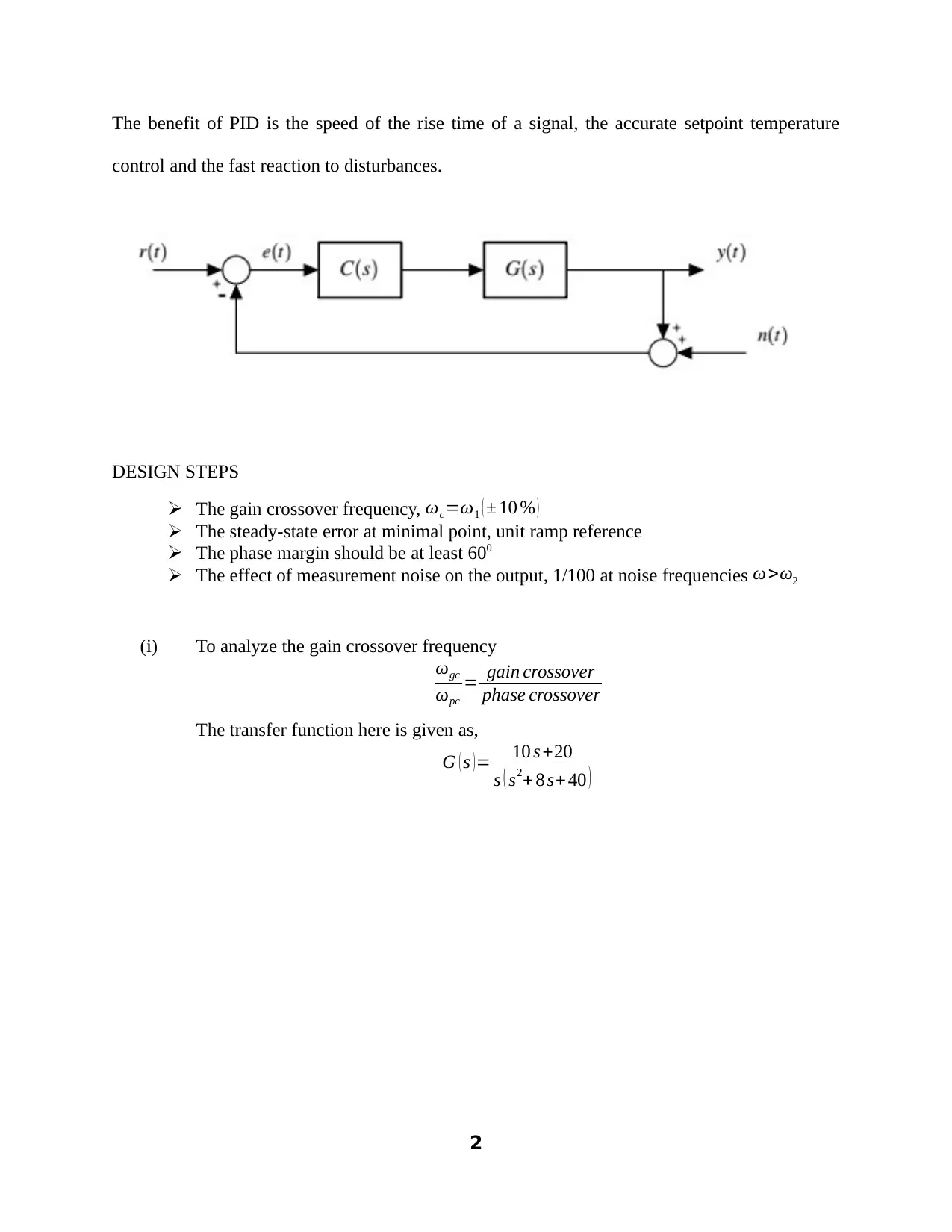
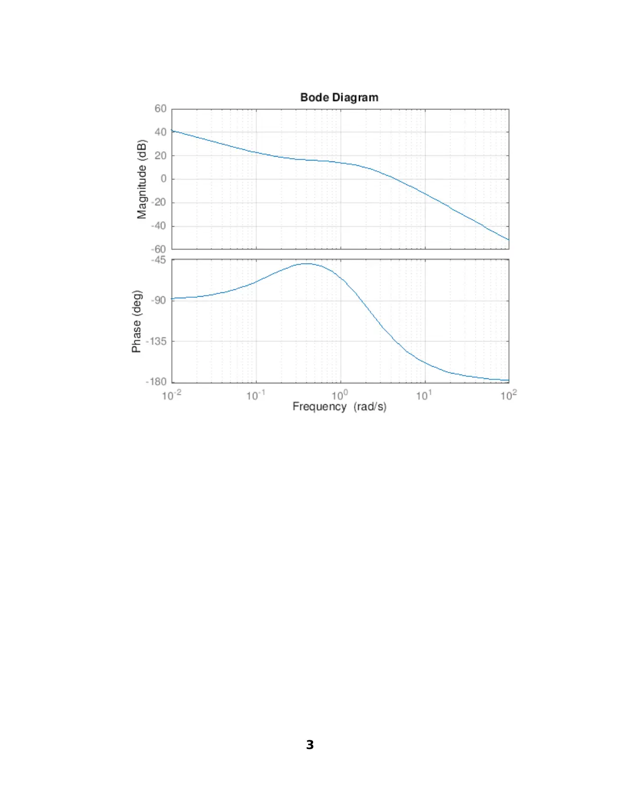
This project details the design and analysis of a control system using proportional, integral, and derivative (PID) controllers within the context of a linear time-invariant (LTI) system. The assignment explores the relationships between input and output signals, transforming the system into the s-domain for computational purposes. The project emphasizes the use of block diagrams for signal flow understanding and system modeling. It investigates the application of proportional, integral, and derivative control strategies, discussing their respective advantages and disadvantages, and provides guidelines for controller adjustments. Key design criteria such as gain crossover frequency, steady-state error, phase margin, and the impact of measurement noise are addressed. The student utilizes MATLAB to simulate the system's response to a ramp input, analyzing the transient and steady-state behavior. The results are presented graphically, illustrating the effects of each controller component on the system's performance, including rise time, overshoot, and settling time. The discussion section reflects on the trial-and-error design process and the importance of stability analysis using root locus. The project concludes with recommendations for achieving desired system performance and emphasizes the role of feedback loops in ensuring the intended output despite disturbances.
tabler-icon-diamond-filled.svg

Contribute Materials

Your contribution can guide someone’s learning journey. Share your documents today.
Document Page
UNIVERSITY AFFILIATION
DEPARTMENT OR FACULTY
Student name
Student registration number
Professor (tutor)
Date of submission
DESIGN ASSIGNMENT
OVERVIEW
tabler-icon-diamond-filled.svg

Secure Best Marks with AI Grader

Need help grading? Try our AI Grader for instant feedback on your assignments.
Document Page
In the time domain, there is an input-output relationship that can be expressed as a closed
loop or open loop system. The system is referred to as linear time invariant when the parameters
that constitute the system are time invariant. For computation purposes, the LTI is transformed
into the s-domain or Laplace domain. The block diagram representation below enables one to
gain an understanding of the signal flows in the system, modelling of complex systems from
simple building blocks, and to allow for the generation of the system transfer function. The plant
system, G(s), is under control. Proportional control can be recommended for fast-response
systems with a large transmission coefficient. To adjust the proportional controller, you should
first set the maximum proportion constant where in the yield power declines to zero. When the
calculated value is stabilized, set a quantified value and gradually diminish the proportion
coefficient and the control error will decrease. If there are periodic fluctuations in the structure,
the proportion gain constant should be augmented so that control error is negligible, the periodic
alternations decrease to the edge. PI control provides zero control error and is insensitive to
interference of the measurement channel. The PI control disadvantage is slow reaction to
disturbances. To adjust the PI controller, you should first set the integration time equal to zero,
and the maximum proportion time. Then by decreasing the coefficient of proportionality, achieve
periodic oscillations in the system. Close to the optimum value of the coefficient of
proportionality is twice higher than that at which any hesitation, and close to the optimum value
of the integration time constant - is 20% less than the oscillation period. The higher the
integration coefficient, the slower the accumulated integration constant value. The higher the
differentiation factor, the greater the response of the system to the disturbance. The PID
controller is used in inertial systems with relatively low noise level of the measuring channel.
1
Document Page
The benefit of PID is the speed of the rise time of a signal, the accurate setpoint temperature
control and the fast reaction to disturbances.
DESIGN STEPS
The gain crossover frequency, ωc=ω1 ( ± 10 % )
The steady-state error at minimal point, unit ramp reference
The phase margin should be at least 600
The effect of measurement noise on the output, 1/100 at noise frequencies ω >ω2
(i) To analyze the gain crossover frequency
ωgc
ωpc
= gain crossover
phase crossover
The transfer function here is given as,
G ( s ) = 10 s +20
s ( s2+ 8 s+ 40 )
2
Document Page
3
tabler-icon-diamond-filled.svg

Secure Best Marks with AI Grader

Need help grading? Try our AI Grader for instant feedback on your assignments.
Document Page
(ii) To analyze the steady state error response for unit ramp response
The controller seeks to manipulate the error. The error is given as,
e ( t )= process variablesetpoint
e ( t )=PV SP
The steady state error for a ramp input At is,
ess=lim
s 0
s ( A s2
1+ C ( s ) G ( s ) )
¿ lim
s 0 ( A
s ( 1+ C ( s ) G ( s ) ) )
4
Document Page
¿ lim
s 0
s ( A
s+ sC ( s ) G ( s ) )
For a stable system of type 2,
ess=lim
s 0
s ( A s2
1+C ( s ) G ( s ) )=0
Analyzing the characteristic equation
5
Document Page
(iii) To analyze the reduced rise time
Adding a derivative controller to the controller system,
6
tabler-icon-diamond-filled.svg

Paraphrase This Document

Need a fresh take? Get an instant paraphrase of this document with our AI Paraphraser
Document Page
Using MATLAB, it is achieved as,
% Design of a control system using the ramp input
clc
clear
close all
7
Document Page
format short
% Controller design with 4 design criterions to meet
a1=10;
a2=20;
b1=8;
b2=400;
w1=40;
w2=600;
%% elastic motor system
s=tf('s');
num=[a1 a2];
den=[1 b1 b2 0];
Gs=tf(num,den)
t = 0:100;
u = t;
[y,x] = lsim(Gs,u,t);
figure(1)
plot(t,y,t,u)
xlabel('Time(secs)')
ylabel('Amplitude')
title('The proportional Controller Ramp Response')
%% PROPORTIONAL CONTROLLER
k=2.5; % proportional constant, Kp (Design criterion 1)
Cs=k;
Ls=Cs*Gs;
% To meet Design criterion 2: wc=w1=4 (tolerance of about 10%)
figure(2)
%bodeplot(Ls)
grid on
[Gm1, Pm1,Wgm1,Wpm1]=margin(Ls)
grid on
[mag,phase,w]=bode(Ls,w1)
[Mp,k]=max(mag)
% for a unit ramp input the response is obtained as,
num=poly([a1 a2 0]);
8
Document Page
den=poly([1 b1 b2]);
Ps=Gs;
Ts=feedback(Ps,1) %Noise is introduced, No unity feedback
t=0:0.1:25;
u=t;
[y,t,x]=lsim(Ts,u,t)
figure(3)
plot(t,y,'y',t,u,'m')
xlabel('Time (sec)')
ylabel('Amplitude')
title('Unit-ramp response with PI controller')
Kv=32.08;
Ls1=Kv*Ls
sysCL=feedback(Ls1,1)
t=0:100;
u=t;
[y1,t1,x1]=lsim(sysCL,u,t)
figure(4)
plot(t,y1,'b',t,u,'r')
xlabel('Time (sec)')
ylabel('Amplitude')
title('Steady state error Transient Response')
The steady state transient response is obtained while the steady state error is designed
to get to a negligible value,
9
tabler-icon-diamond-filled.svg

Secure Best Marks with AI Grader

Need help grading? Try our AI Grader for instant feedback on your assignments.
Document Page
DISCUSSION
This design was carried out as a trial and error kind of design where the proportional,
integral, and derivative values were crafted after test and block updates. The proportional
constant helped in decreasing the rise time and steady state error though it caused an increase in
overshoot (Nise, 2003). The integral component led to a further decrease in rise time, increase in
overshoot and settling time but it eliminated the steady state error. To determine the system
stability, the tests required one to observe the root locus response. For the poles on the left-hand
side, the system was considered stable. The proportional, integral, and derivative components
were adjusted to meet the set-up requirements. The noise fragment in the feedback loop affected
the amplitude as illustrated in the output graphs. The system was analyzed as an open loop
system using a combination of controller and plant transfer functions as the open-loop transfer
function, L(s). A controller of this nature can provide the control action as required by a given
industrial application or process (Golnaraghi & Kuo, 2009). The PI controller does not work for
systems that are faced with lag problems. Some systems have lag in their response of 180
degrees or more such as the double integrator. The controller’s performance is rated against its
ability to control the error especially in a noisy environment. The derivative controller addition
seeks to improve the phase by giving the system a lead of 50 degrees hence an improvement in
10
Document Page
the rise time. Controllers in linear time-invariant systems are used to ensure that the intended
output is yielded despite the errors and disturbances in the surrounding. The control systems are
used in industrial applications as they tend to improve the industrial processes, the efficacy of
energy usage, progressive vehicle control which includes the swift transport alongside other
merits (Dorf & Bishop, 2008)
CONCLUSION AND RECOMMENDATIONS
In a nutshell, the system should have a low error once it settles hence it is considered to have a
good steady-state response. The controller seeks to ensure that the intended output of the process,
G(s), is obtained despite the effects of the noise signal at the feedback loop. The variables that
need to be controlled are the gain crossover frequency, steady state error, phase margin, and the
noise measure. The impact of the feedback loop is to ensure that the desired output is obtained
from the system. The loop takes back the actual output to the summer to check for errors and the
output signal from the summer is taken into a controller for appropriate adjustment. The
feedback loop performs the measurement and signal transmission of the system.
REFERENCES
Dorf, R. C. & Bishop, R. H., 2008. Modern Control Systems. 3rd ed. s.l.:Addison Wesley
Longman, Inc.
Karl, J. A., 2002. PID Control: Introduction to PID controllers. s.l.:s.n.
Kuo, B. C., 2001. Automatic Control Systems. 6th ed. s.l.:Prentice Hall, Inc.
Tehrani, A. K. & Augustin , M., n.d. Introduction to PID Controllers- Theory, Tuning and
Application to Frontier Areas. [Online] Available at: https://www.intechopen.com
11
chevron_up_icon
1 out of 12
circle_padding
hide_on_mobile
zoom_out_icon
logo.png

Your All-in-One AI-Powered Toolkit for Academic Success.

Available 24*7 on WhatsApp / Email

[object Object]