Control System Design for Robots: Single Link Manipulator - ELEC-848

Verified

Added on  2022/09/13

|5
|685
|17
Project
AI Summary
This assignment focuses on the design and simulation of control systems for a single link manipulator, as outlined in the ELEC-848 course. The project involves implementing and comparing the performance of various control strategies, including inverse dynamics, robust inverse dynamics (with hard and soft switches), sliding mode control (with hard and soft switches), and the Slotine and Li adaptive controller. The simulation is conducted using Simulink, with the actual manipulator dynamics modeled using specific parameter values and estimated values for controller design. The desired position input is defined, and the performance of each controller is evaluated through plots of position, position error, control command, and a 3D Lyapunov function. The analysis includes a discussion of the stability and performance characteristics of each controller, with references to relevant research papers. The objective is to provide a comprehensive understanding of control system design for robotic manipulators, emphasizing practical implementation and performance evaluation.
Document Page
Electronics
Robot control
ELEC-848: Control Systems Design for Robots and Telerobots
Assignment # 3
Single link manipulator control
Student Name –
Student ID -
tabler-icon-diamond-filled.svg

Paraphrase This Document

Need a fresh take? Get an instant paraphrase of this document with our AI Paraphraser
Document Page
Introduction :
Here, a 1 dof pendulum is considered. A single link manipulator has been designed.
Method :
The single link manipulator can be described in terms of the equation given by :
I θ’’ + MgL sin (θ) = u
Here, 5 <= I <= 10 and 5 <= MgL <= 10
The above system is designed and simulated using the Matlab software. The parameter values
used are : I = 10 and Mgl = 10. The estimate is ‘5’ for both the parameters.
Discussion :
The single link manipulator can be designed. It can be controlled by the help of several
control systems. The position control and the path control can be done using the PID
( Proportional Integral Derivative ) controller. The PID controller is very simple to design
and makes the system stable. The values of various parameters are obtained by measurement
system. The values obtained are fed as input to the system. Based on the inputs, the controller
generates an output in a stable manner The aim is to maintain the angle of rotation at a fixed
position. Any oscillation angle must be removed at the end. The software Matlab can be used
to design the controller.
Document Page
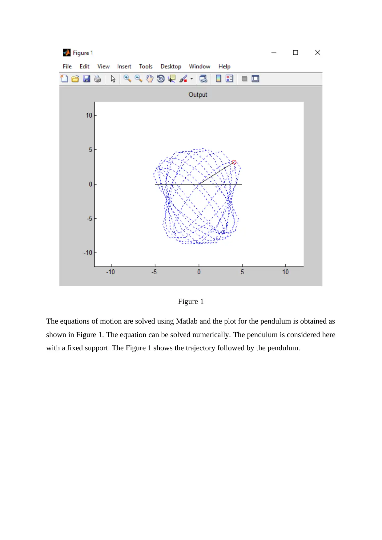
Figure 1
The equations of motion are solved using Matlab and the plot for the pendulum is obtained as
shown in Figure 1. The equation can be solved numerically. The pendulum is considered here
with a fixed support. The Figure 1 shows the trajectory followed by the pendulum.
Document Page
0 0.5 1 1.5 2 2.5 3 3.5 4 4.5 5
-100
0
100
200
time (s)
Joint Angle
Joint Angle (Deg) vs Time
0 0.5 1 1.5 2 2.5 3 3.5 4 4.5 5
-400
-200
0
200
400
time (s)
Joint Velocity
Joint Velocity vs Time
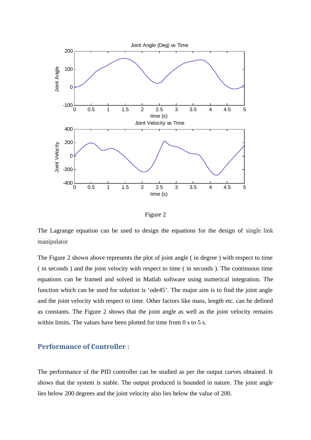
Figure 2
The Lagrange equation can be used to design the equations for the design of single link
manipulator
The Figure 2 shown above represents the plot of joint angle ( in degree ) with respect to time
( in seconds ) and the joint velocity with respect to time ( in seconds ). The continuous time
equations can be framed and solved in Matlab software using numerical integration. The
function which can be used for solution is ‘ode45’. The major aim is to find the joint angle
and the joint velocity with respect to time. Other factors like mass, length etc. can be defined
as constants. The Figure 2 shows that the joint angle as well as the joint velocity remains
within limits. The values have been plotted for time from 0 s to 5 s.
Performance of Controller :
The performance of the PID controller can be studied as per the output curves obtained. It
shows that the system is stable. The output produced is bounded in nature. The joint angle
lies below 200 degrees and the joint velocity also lies below the value of 200.
tabler-icon-diamond-filled.svg

Paraphrase This Document

Need a fresh take? Get an instant paraphrase of this document with our AI Paraphraser
Document Page
References :
Akyüz, İ. H., BİNGÜL, Z., & Kizir, S. (2012). Cascade fuzzy logic control of a single-link
flexible-joint manipulator. Turkish Journal of Electrical Engineering & Computer
Sciences, 20(5), 713-726.
Kiang, C. T., Spowage, A., & Yoong, C. K. (2015). Review of control and sensor system of
flexible manipulator. Journal of Intelligent & Robotic Systems, 77(1), 187-213.
Li, Y., Tong, S., & Li, T. (2013). Adaptive fuzzy output feedback control for a single-link
flexible robot manipulator driven DC motor via backstepping. Nonlinear Analysis: Real
World Applications, 14(1), 483-494.
Shawky, A., Zydek, D., Elhalwagy, Y. Z., & Ordys, A. (2013). Modeling and nonlinear
control of a flexible-link manipulator. Applied Mathematical Modelling, 37(23), 9591-9602.
chevron_up_icon
1 out of 5
circle_padding
hide_on_mobile
zoom_out_icon
[object Object]