Comprehensive Report: Comparing DC and AC Motor Design and Operation

Verified

Added on  2022/11/25

|11
|1409
|332
Report
AI Summary
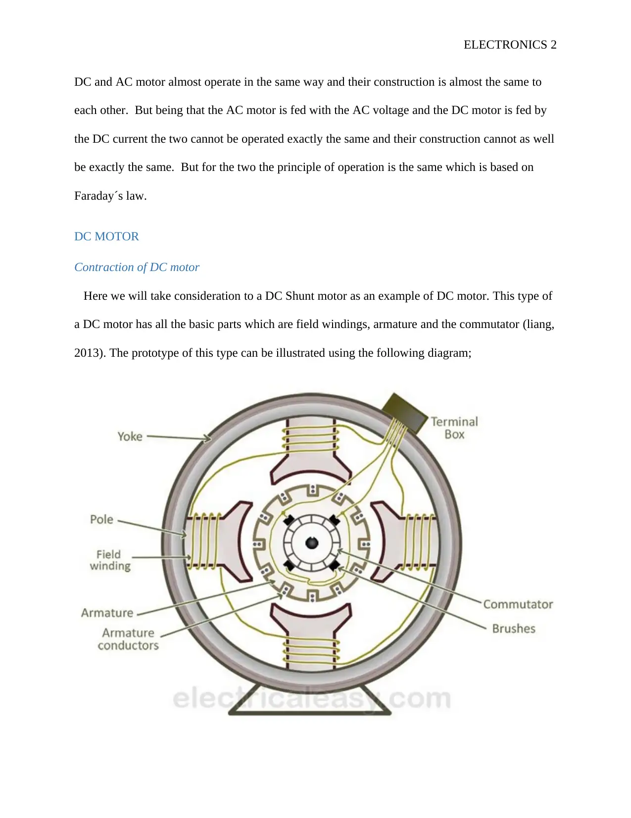
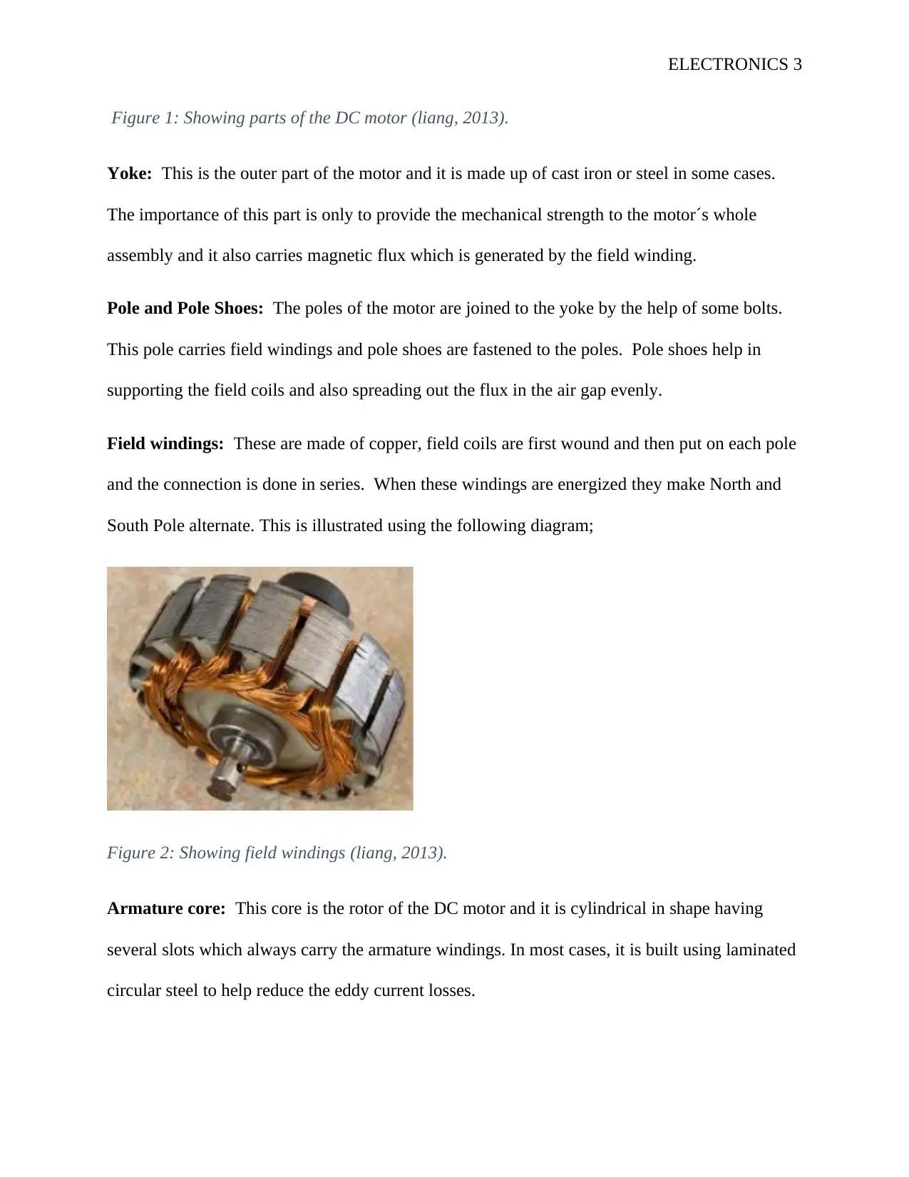
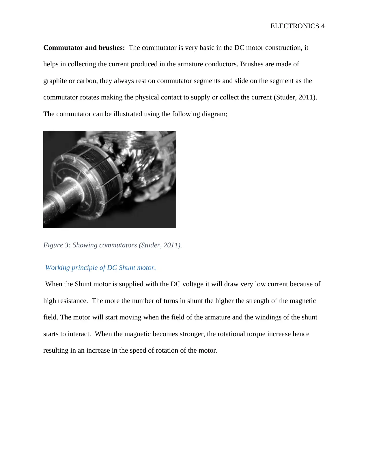
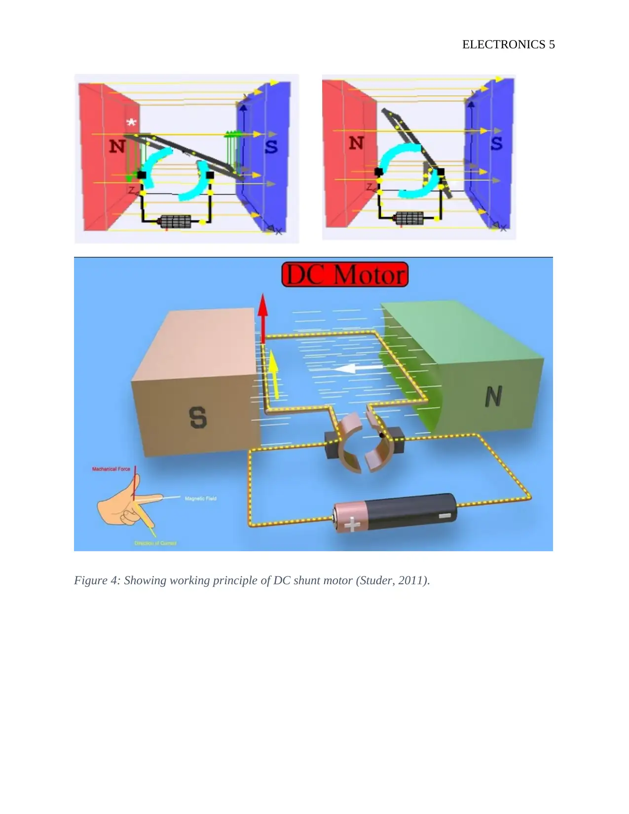
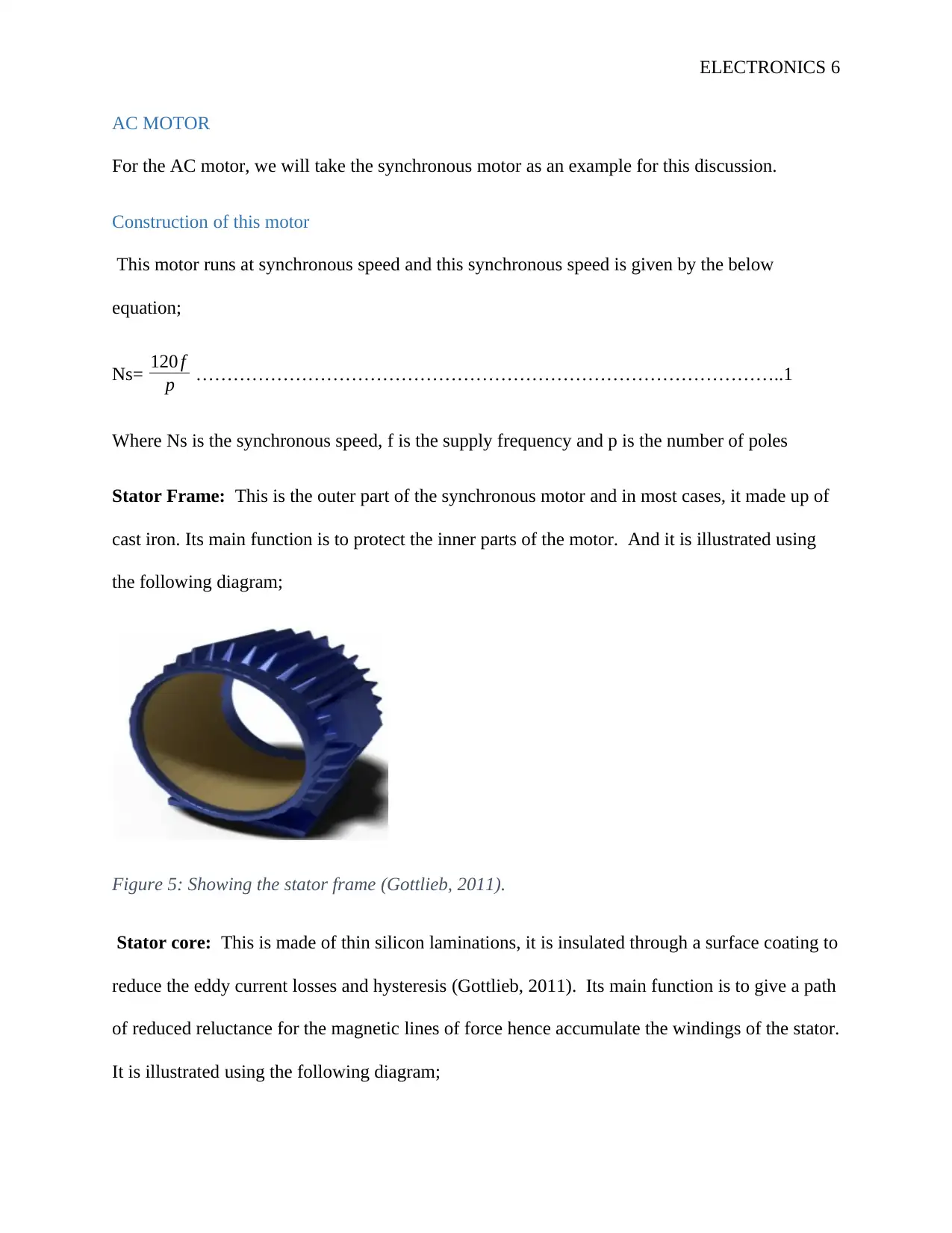
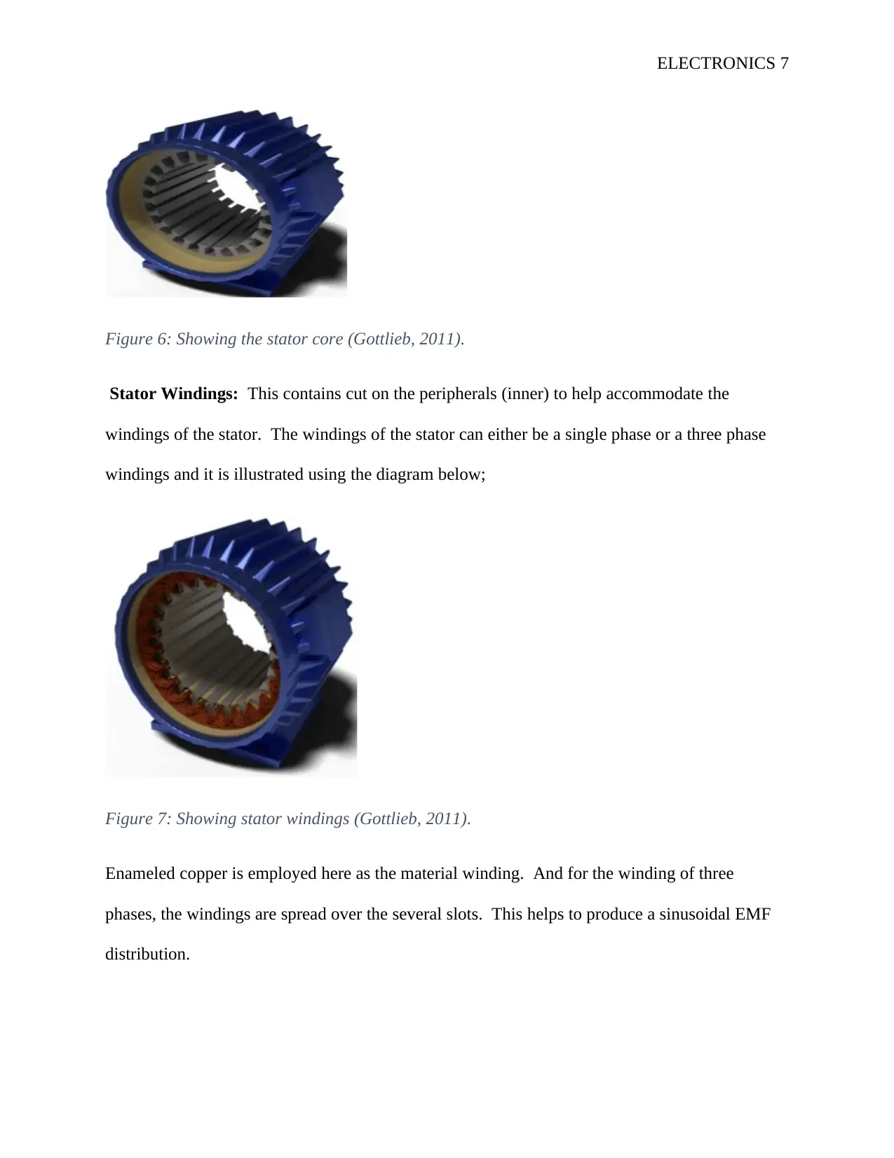
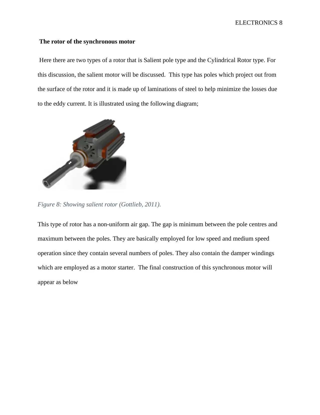
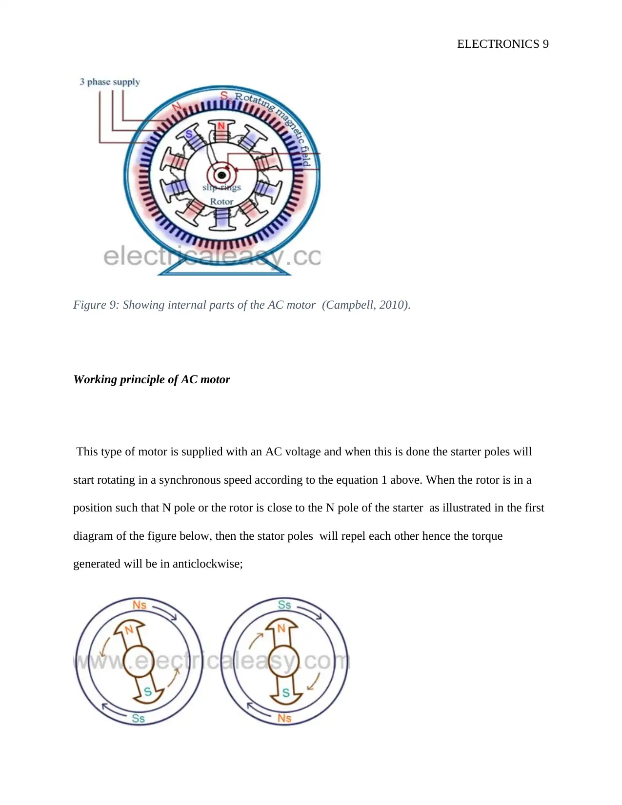
This report provides a comprehensive comparison of DC and AC motors, focusing on their construction and operational principles. The report begins by examining the DC shunt motor, detailing its components such as the yoke, poles, field windings, armature core, commutator, and brushes. It then explains the working principle of the DC motor, emphasizing the interaction between the armature and field windings. The report then transitions to the AC synchronous motor, describing its stator frame, stator core, stator windings, and rotor (specifically the salient pole type). The working principle of the AC motor is explained, highlighting how the rotating stator poles interact with the rotor to generate torque. The report references key equations and diagrams to illustrate the concepts. This analysis aims to provide a clear understanding of the similarities and differences between these two types of electric motors.
Document Page
ELECTRONICS 1
ELECTRONICS
By Name
Course
Instructor
Institution
Location
Date
tabler-icon-diamond-filled.svg

Paraphrase This Document

Need a fresh take? Get an instant paraphrase of this document with our AI Paraphraser
Document Page
ELECTRONICS 2
DC and AC motor almost operate in the same way and their construction is almost the same to
each other. But being that the AC motor is fed with the AC voltage and the DC motor is fed by
the DC current the two cannot be operated exactly the same and their construction cannot as well
be exactly the same. But for the two the principle of operation is the same which is based on
Faraday´s law.
DC MOTOR
Contraction of DC motor
Here we will take consideration to a DC Shunt motor as an example of DC motor. This type of
a DC motor has all the basic parts which are field windings, armature and the commutator (liang,
2013). The prototype of this type can be illustrated using the following diagram;
Document Page
ELECTRONICS 3
Figure 1: Showing parts of the DC motor (liang, 2013).
Yoke: This is the outer part of the motor and it is made up of cast iron or steel in some cases.
The importance of this part is only to provide the mechanical strength to the motor´s whole
assembly and it also carries magnetic flux which is generated by the field winding.
Pole and Pole Shoes: The poles of the motor are joined to the yoke by the help of some bolts.
This pole carries field windings and pole shoes are fastened to the poles. Pole shoes help in
supporting the field coils and also spreading out the flux in the air gap evenly.
Field windings: These are made of copper, field coils are first wound and then put on each pole
and the connection is done in series. When these windings are energized they make North and
South Pole alternate. This is illustrated using the following diagram;
Figure 2: Showing field windings (liang, 2013).
Armature core: This core is the rotor of the DC motor and it is cylindrical in shape having
several slots which always carry the armature windings. In most cases, it is built using laminated
circular steel to help reduce the eddy current losses.
Document Page
ELECTRONICS 4
Commutator and brushes: The commutator is very basic in the DC motor construction, it
helps in collecting the current produced in the armature conductors. Brushes are made of
graphite or carbon, they always rest on commutator segments and slide on the segment as the
commutator rotates making the physical contact to supply or collect the current (Studer, 2011).
The commutator can be illustrated using the following diagram;
Figure 3: Showing commutators (Studer, 2011).
Working principle of DC Shunt motor.
When the Shunt motor is supplied with the DC voltage it will draw very low current because of
high resistance. The more the number of turns in shunt the higher the strength of the magnetic
field. The motor will start moving when the field of the armature and the windings of the shunt
starts to interact. When the magnetic becomes stronger, the rotational torque increase hence
resulting in an increase in the speed of rotation of the motor.
tabler-icon-diamond-filled.svg

Paraphrase This Document

Need a fresh take? Get an instant paraphrase of this document with our AI Paraphraser
Document Page
ELECTRONICS 5
Figure 4: Showing working principle of DC shunt motor (Studer, 2011).
Document Page
ELECTRONICS 6
AC MOTOR
For the AC motor, we will take the synchronous motor as an example for this discussion.
Construction of this motor
This motor runs at synchronous speed and this synchronous speed is given by the below
equation;
Ns= 120 f
p …………………………………………………………………………………..1
Where Ns is the synchronous speed, f is the supply frequency and p is the number of poles
Stator Frame: This is the outer part of the synchronous motor and in most cases, it made up of
cast iron. Its main function is to protect the inner parts of the motor. And it is illustrated using
the following diagram;
Figure 5: Showing the stator frame (Gottlieb, 2011).
Stator core: This is made of thin silicon laminations, it is insulated through a surface coating to
reduce the eddy current losses and hysteresis (Gottlieb, 2011). Its main function is to give a path
of reduced reluctance for the magnetic lines of force hence accumulate the windings of the stator.
It is illustrated using the following diagram;
Document Page
ELECTRONICS 7
Figure 6: Showing the stator core (Gottlieb, 2011).
Stator Windings: This contains cut on the peripherals (inner) to help accommodate the
windings of the stator. The windings of the stator can either be a single phase or a three phase
windings and it is illustrated using the diagram below;
Figure 7: Showing stator windings (Gottlieb, 2011).
Enameled copper is employed here as the material winding. And for the winding of three
phases, the windings are spread over the several slots. This helps to produce a sinusoidal EMF
distribution.
tabler-icon-diamond-filled.svg

Paraphrase This Document

Need a fresh take? Get an instant paraphrase of this document with our AI Paraphraser
Document Page
ELECTRONICS 8
The rotor of the synchronous motor
Here there are two types of a rotor that is Salient pole type and the Cylindrical Rotor type. For
this discussion, the salient motor will be discussed. This type has poles which project out from
the surface of the rotor and it is made up of laminations of steel to help minimize the losses due
to the eddy current. It is illustrated using the following diagram;
Figure 8: Showing salient rotor (Gottlieb, 2011).
This type of rotor has a non-uniform air gap. The gap is minimum between the pole centres and
maximum between the poles. They are basically employed for low speed and medium speed
operation since they contain several numbers of poles. They also contain the damper windings
which are employed as a motor starter. The final construction of this synchronous motor will
appear as below
Document Page
ELECTRONICS 9
Figure 9: Showing internal parts of the AC motor (Campbell, 2010).
Working principle of AC motor
This type of motor is supplied with an AC voltage and when this is done the starter poles will
start rotating in a synchronous speed according to the equation 1 above. When the rotor is in a
position such that N pole or the rotor is close to the N pole of the starter as illustrated in the first
diagram of the figure below, then the stator poles will repel each other hence the torque
generated will be in anticlockwise;
Document Page
ELECTRONICS 10
Figure 10: Showing the working principle of AC synchronous motors (Campbell, 2010).
The stator poles will revolve with a synchronous speed and rotate very fast and also interchange
their positions. While in the next position the poles of the motor stator will attract the poles of
the rotor hence the torque generated will be in a clockwise direction and this is illustrated in the
second figure of the diagram above (Campbell, 2010). Therefore the rotor will be subjected to an
abrupt reversing torque hence the motor will not start.
But in case the rotor is rotated until the synchronous speed of the stator through an external
force and the rotor field excited near the synchronous speed, the poles of the stator will be
attracting the opposite poles of the rotor. The rotor now will undergo unidirectional torque. The
rotor and the opposite poles of the stator will be locked with each other hence the rotor will run
at the synchronous speed.
tabler-icon-diamond-filled.svg

Paraphrase This Document

Need a fresh take? Get an instant paraphrase of this document with our AI Paraphraser
Document Page
ELECTRONICS 11
Bibliography
Campbell, S., 2010. Solid-State AC Motor Controls: Selection and Application. 3rd ed. New York : CRC
Press.
Gottlieb, I., 2011. Practical Electric Motor Handbook. 2nd ed. Chicago: Elsevier.
liang, X. C., 2013. Permanent Magnet Brushless DC Motor Drives and Controls. 3rd ed. Hull: John Wiley &
Sons.
Studer, P., 2011. Development of a brushless dc motor for satellite application. 1st ed. Hull: National
Aeronautics and Space Administration.
chevron_up_icon
1 out of 11
circle_padding
hide_on_mobile
zoom_out_icon
[object Object]