University of Leeds: DC Motor Speed Control PI Controller Report
VerifiedAdded on 2022/08/26
|12
|2505
|13
Report
AI Summary
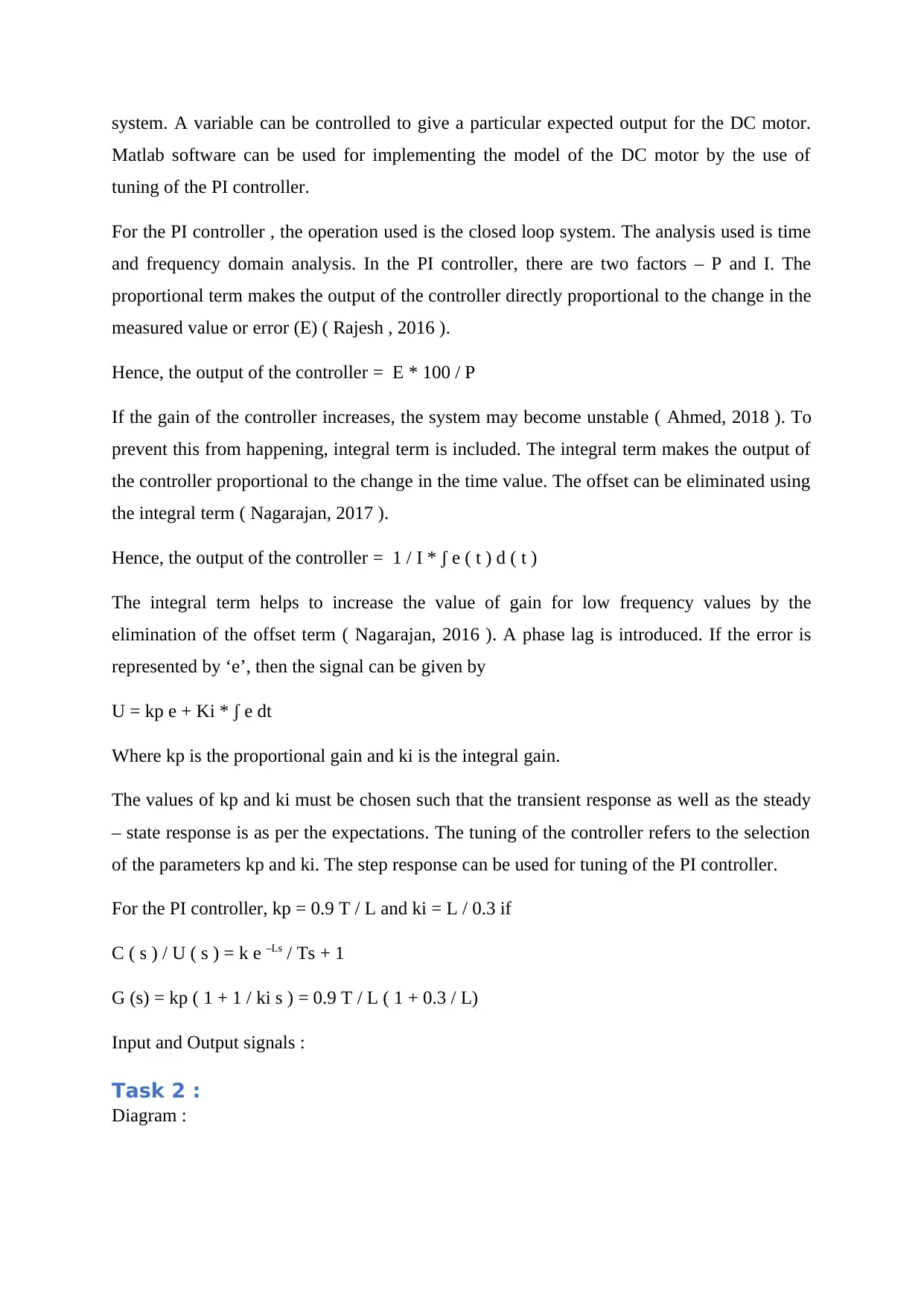
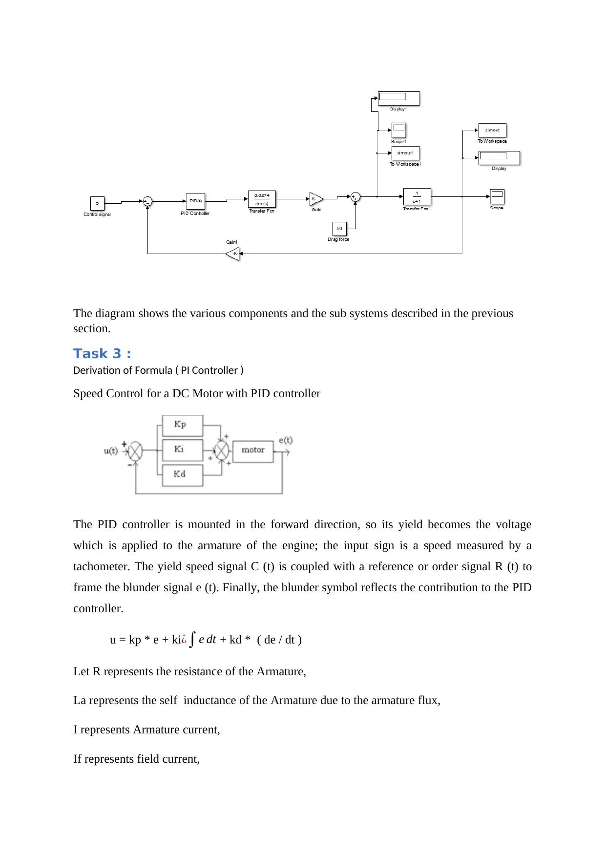
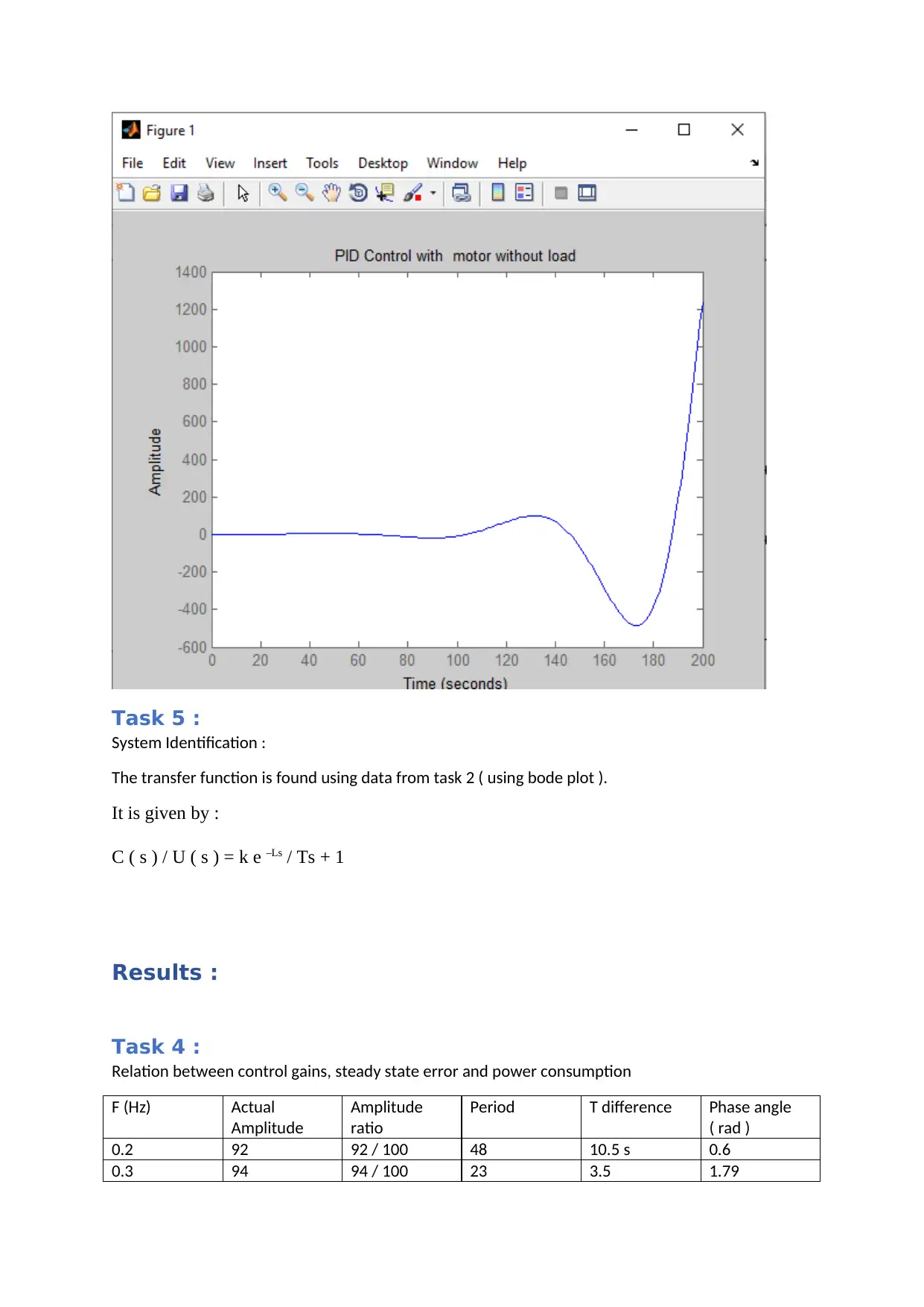
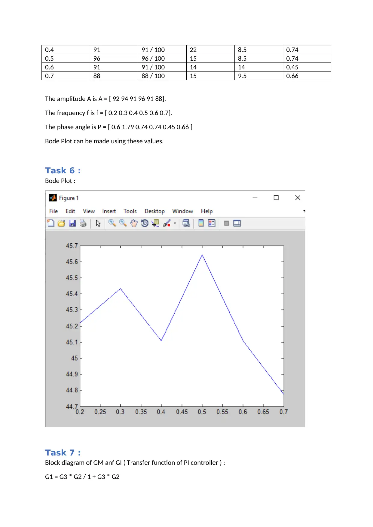
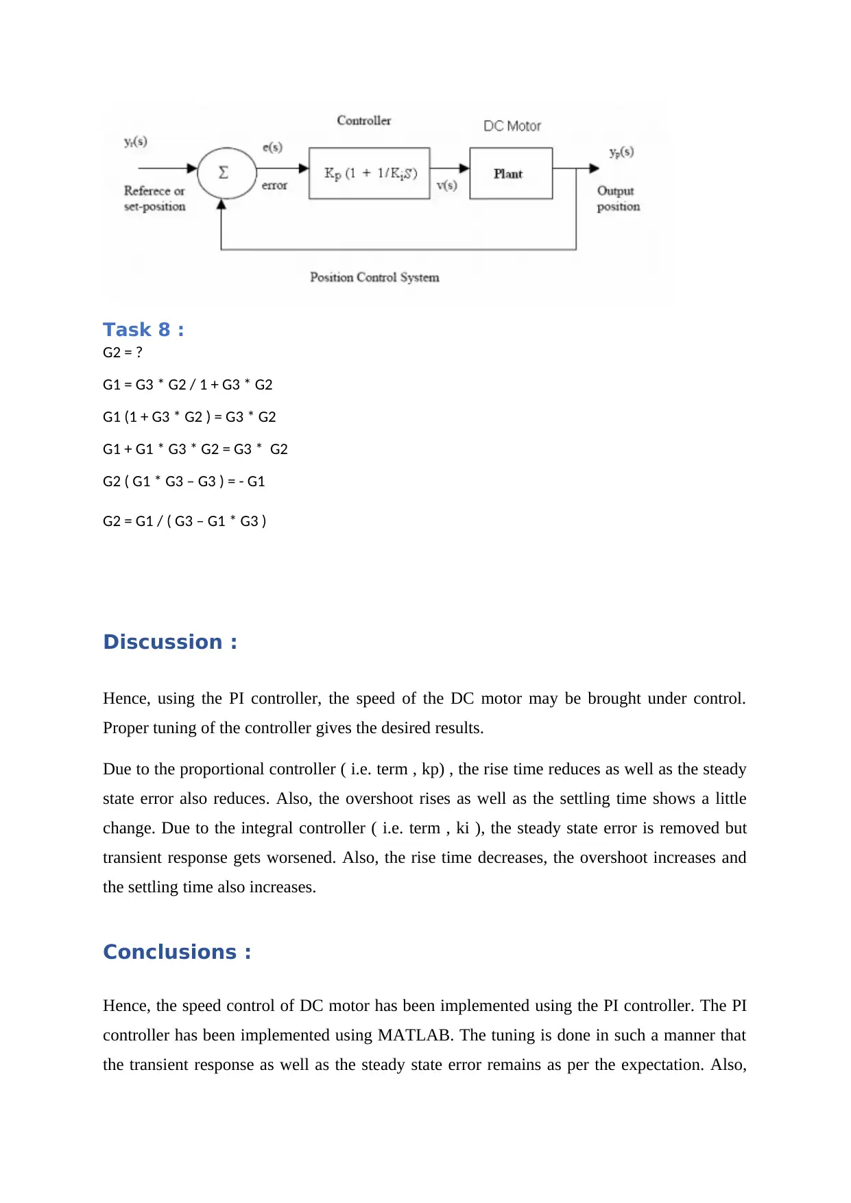
This report details a lab experiment focused on DC motor speed control using a Proportional-Integral (PI) controller. The experiment involves understanding the components of a DC motor and constructing a speed control system. The report outlines the methods, including the use of an Arduino board, encoder, and software like MATLAB, to count encoder pulses and implement the PI controller. The objectives include identifying components, constructing the system, understanding LabView diagrams, constructing PI control, tuning gains, and identifying a transfer function. The report includes derivations, formulas, and analysis of the control gains, steady-state error, and power consumption, with results presented in tables and Bode plots. The discussion section analyzes the effects of proportional and integral controllers on rise time, steady-state error, overshoot, and settling time. The conclusion summarizes the successful implementation of DC motor speed control using a PI controller, highlighting the importance of proper tuning for desired performance.

DC Motor Speed Control using PI Control
Student Name –
ID number –
Attended Lab Session Date / Time –
Student Name –
ID number –
Attended Lab Session Date / Time –
Paraphrase This Document
Need a fresh take? Get an instant paraphrase of this document with our AI Paraphraser

Introduction
The device operation relies on straightforward electromagnetism in any electrical device. A
current-conveying conductor creates a field which is attractive in nature. When a current-
carrying conductor is put in an attractive field outside, a power corresponding to the current
in the conductor and the outer attractive field strength will be experienced. In a magnet, the
opposite polarities ( N and S ) pull in, while they repulse like polarities ( N and West, East
and S ). The internal arrangement of a DC engine is designed to saddle the attractive
collaboration between a current-conveying conductor and an attractive field outside to create
rotational motion.
That DC engine consists of 6 essential parts including hub, rotor called as armature, stator,
switch, field magnet and brushes. The outer attractive field is delivered using perpetual
magnets of good quality in most normal DC engines. The stator is the engine's stationary
component-this includes the engine packaging, at least 2 enduring bits of magnet shaft. The
rotor in relation to the stator, together with the pivot and the appended commutator turn. For
most of the cases, the rotor consists of windings on a center, the windings being connected
electrically to the commutator. The Figure 1 shows a typical engine design inside the stator or
field magnets, with the rotor.
The brushes ' geometry, commutator contacts, and rotor windings are designed such that the p
olarity of the stimulated winding and the stator magnet is bent when force is applied, and the
rotor can rotate until it is almost aligned with the field magnets of the stator. The brushes shift
to the following switching contacts as the rotor arrives at arrangement and allows the
following winding. Because of our two shaft engine configurations, the spinning action due
to revolution around the current bearing through the spinning action of the rotor which causes
a flip in the enticing area of the rotor, which forces it to stay pivotal.
Nonetheless, taking all the factors under consideration, the DC engines are going to regularly
have many posts (3 is a common count). Actually, the commutator stays away from dead
ends. A two-post model engine gets stuck in case the rotor is actually at the centre of the turn
splendidly aligned along with the field magnets. In the meantime, using a two-
shaft motor, the switch leads to the
shorting of the supply of power, i.e. the two brushes simultaneously touch all switching conta
cts. This would be bad for the supply of power, squandering energy and also hurting parts of t

he engine.
Another drawback of such a simple engine is that it will present a high torque ripple measure.
The torque it produces is cyclic in nature.
The most widely used actuators are the Brushed DC motors.They are available in different siz
es and can be optimized for output angular velocity or torque generation for various purposes.
During this lab, high powered 50:1 gear ratio and low powered 148:1 gear ratio 919D series
motors are used, which are connected to an optical encoder 600EN-128-CBL as shown in
Figure 1.
Fig1 : DC Motor and DC motor control
Aims & Objectives
The study of the concept of the speed control of DC motor is the major objective..
The aim of the lab experiment is the understanding of the speed control of DC motor.
Completing this lab, you would be capable to
• Identify the desired components for DC-motor speed control system
• Construct a speed control of DC motor system using the components
• Understand a LabView diagram to obtain sensor signal
• Construct a PI (Proportional-Integral) control in LabView and MATLAB
• Tune the PI control gains to achieve a desired performance
⊘ This is a preview!⊘
Do you want full access?
Subscribe today to unlock all pages.

Trusted by 1+ million students worldwide

• Identify a transfer function between input and output signals
Methods :
Task 1 :
Hardware and Software Components :
The Hardware needed is a DC motor, a battery, diode, transistor, breadboard, wires and
Arduino board. The encoder can be used to estimate the angular speed of the motor. The
Arduino board can be used to count the encoder pulses using digital inputs. A digital output
can be used for switching the transistor on and off, to connect the DC voltage supply to the
motor ( Bhatti , 2016 ).
The software used is Matlab.
Functions :
For the advancement of the industries, the automatic control needs to be employed. The DC
motor control is one such field. Many different types of controller units can be used for
controlling a DC motor. An example of one such design is the PI controller. The Proportional
and Integral controller reduces the dependence on a manual operator for controlling the
Paraphrase This Document
Need a fresh take? Get an instant paraphrase of this document with our AI Paraphraser

system. A variable can be controlled to give a particular expected output for the DC motor.
Matlab software can be used for implementing the model of the DC motor by the use of
tuning of the PI controller.
For the PI controller , the operation used is the closed loop system. The analysis used is time
and frequency domain analysis. In the PI controller, there are two factors – P and I. The
proportional term makes the output of the controller directly proportional to the change in the
measured value or error (E) ( Rajesh , 2016 ).
Hence, the output of the controller = E * 100 / P
If the gain of the controller increases, the system may become unstable ( Ahmed, 2018 ). To
prevent this from happening, integral term is included. The integral term makes the output of
the controller proportional to the change in the time value. The offset can be eliminated using
the integral term ( Nagarajan, 2017 ).
Hence, the output of the controller = 1 / I * ʃ e ( t ) d ( t )
The integral term helps to increase the value of gain for low frequency values by the
elimination of the offset term ( Nagarajan, 2016 ). A phase lag is introduced. If the error is
represented by ‘e’, then the signal can be given by
U = kp e + Ki * ʃ e dt
Where kp is the proportional gain and ki is the integral gain.
The values of kp and ki must be chosen such that the transient response as well as the steady
– state response is as per the expectations. The tuning of the controller refers to the selection
of the parameters kp and ki. The step response can be used for tuning of the PI controller.
For the PI controller, kp = 0.9 T / L and ki = L / 0.3 if
C ( s ) / U ( s ) = k e –Ls / Ts + 1
G (s) = kp ( 1 + 1 / ki s ) = 0.9 T / L ( 1 + 0.3 / L)
Input and Output signals :
Task 2 :
Diagram :

The diagram shows the various components and the sub systems described in the previous
section.
Task 3 :
Derivation of Formula ( PI Controller )
Speed Control for a DC Motor with PID controller
The PID controller is mounted in the forward direction, so its yield becomes the voltage
which is applied to the armature of the engine; the input sign is a speed measured by a
tachometer. The yield speed signal C (t) is coupled with a reference or order signal R (t) to
frame the blunder signal e (t). Finally, the blunder symbol reflects the contribution to the PID
controller.
u = kp * e + ki¿∫e dt + kd * ( de / dt )
Let R represents the resistance of the Armature,
La represents the self inductance of the Armature due to the armature flux,
I represents Armature current,
If represents field current,
⊘ This is a preview!⊘
Do you want full access?
Subscribe today to unlock all pages.

Trusted by 1+ million students worldwide

Eb represents the armature’s Back emf,
V represents the voltage that is applied,
T represents the motor’s torque,
θ represents the Angular displacement for the shaft of the motor,
Ј represents the moment of inertia ( equivalent ) for the shaft of the motor
B represents the Equivalent Coefficient of friction for the shaft of the motor
The air gap flux of the motor is Φ
We know for DC motor Φ ∝ia
Back emf of the motor
Eb ∝ Φ ω
The Kirchoff’s Voltage Law can be applied to the armature circuit to get the following
result :
V= Ra*ia + La(dia/dt) + Eb
The motor’s torque equation can be given by :
T = J (d2θ/dt2) + B (dθ/dt)
Using the Laplace domain we get
T(s) = K Ia(s)
V( s ) = I ( s ) [ R + s L ] + Eb
T(s) = s(Js+B) θ(s)
The speed control of the DC motor may be given by the ratio of the speed to the input
voltage
G(s) = ω(s)/v(s)
The Laplace domain is used for representing the dynamic equations of the system.
The DC motor’s open-loop transfer function is given by :
H ( s ) = C / [ ( Js + B ) ( Ls + R ) + C 2 ]
Paraphrase This Document
Need a fresh take? Get an instant paraphrase of this document with our AI Paraphraser

The PID controller’s transfer function may be given as follows :
Equivalent moment of inertia for the shaft of the motor =0.01
Equivalent friction coefficient for the shaft of the motor = 0.1
Armature self-inductance = 0.5
K = 0.0274;
R = 4;
Kp = 2.5;
Ki = 2;
Kd = 2.5;
PI Control Gain Tuning :
Proportional gain , Kp Integral Gain , Ki Steady state angular
velocity
Measured power
( Ws )
1 0.01 52.3149 4.32
1.5 0.02 49.4193 3.94
2 0.03 48.9594 4.04
2.5 0.04 50.6218 3.96
4 0.06 50.6178 3.58

Task 5 :
System Identification :
The transfer function is found using data from task 2 ( using bode plot ).
It is given by :
C ( s ) / U ( s ) = k e –Ls / Ts + 1
Results :
Task 4 :
Relation between control gains, steady state error and power consumption
F (Hz) Actual
Amplitude
Amplitude
ratio
Period T difference Phase angle
( rad )
0.2 92 92 / 100 48 10.5 s 0.6
0.3 94 94 / 100 23 3.5 1.79
⊘ This is a preview!⊘
Do you want full access?
Subscribe today to unlock all pages.

Trusted by 1+ million students worldwide

0.4 91 91 / 100 22 8.5 0.74
0.5 96 96 / 100 15 8.5 0.74
0.6 91 91 / 100 14 14 0.45
0.7 88 88 / 100 15 9.5 0.66
The amplitude A is A = [ 92 94 91 96 91 88].
The frequency f is f = [ 0.2 0.3 0.4 0.5 0.6 0.7].
The phase angle is P = [ 0.6 1.79 0.74 0.74 0.45 0.66 ]
Bode Plot can be made using these values.
Task 6 :
Bode Plot :
Task 7 :
Block diagram of GM anf GI ( Transfer function of PI controller ) :
G1 = G3 * G2 / 1 + G3 * G2
Paraphrase This Document
Need a fresh take? Get an instant paraphrase of this document with our AI Paraphraser

Task 8 :
G2 = ?
G1 = G3 * G2 / 1 + G3 * G2
G1 (1 + G3 * G2 ) = G3 * G2
G1 + G1 * G3 * G2 = G3 * G2
G2 ( G1 * G3 – G3 ) = - G1
G2 = G1 / ( G3 – G1 * G3 )
Discussion :
Hence, using the PI controller, the speed of the DC motor may be brought under control.
Proper tuning of the controller gives the desired results.
Due to the proportional controller ( i.e. term , kp) , the rise time reduces as well as the steady
state error also reduces. Also, the overshoot rises as well as the settling time shows a little
change. Due to the integral controller ( i.e. term , ki ), the steady state error is removed but
transient response gets worsened. Also, the rise time decreases, the overshoot increases and
the settling time also increases.
Conclusions :
Hence, the speed control of DC motor has been implemented using the PI controller. The PI
controller has been implemented using MATLAB. The tuning is done in such a manner that
the transient response as well as the steady state error remains as per the expectation. Also,

the speed of the DC motor may be successfully brought under control and it can be done in an
automated manner.
References :
Nagarajan, D.R., Sathishkumar, S., Balasubramani, K., Boobalan, C., Naveen, S. and Sridhar,
N., 2016. Chopper fed speed control of DC motor using PI controller. IOSR-Journal of
Electrical and Electronics Engineering (IOSR-JEEE), 11(3), pp.65-69.
Nagarajan, R., Sathishkumar, S., Deepika, S., Keerthana, G., Kiruthika, J.K. and Nandhini,
R., 2017. Implementation of chopper fed speed control of separately excited DC motor using
PI controller. International Journal of Engineering And Computer Science (IJECS), 6(3),
pp.20629-20633.
Ahmed, A.H., Abd El Samie, B. and Ali, A.M., 2018. Comparison between fuzzy logic and
PI control for the speed of BLDC motor. International Journal of Power Electronics and
Drive Systems, 9(3), p.1116.
Rajesh, R. and Krishna, V.R., 2016. Application of DC/DC Buck Power Converter in DC
Motor for Speed Controlling Using PI Controller.
Bhatti, S.A., Malik, S.A. and Daraz, A., 2016, January. Comparison of PI and IP controller
by using Ziegler-Nichols tuning method for speed control of DC motor. In 2016 International
Conference on Intelligent Systems Engineering (ICISE) (pp. 330-334). IEEE.
⊘ This is a preview!⊘
Do you want full access?
Subscribe today to unlock all pages.

Trusted by 1+ million students worldwide
1 out of 12
Related Documents

Your All-in-One AI-Powered Toolkit for Academic Success.
+13062052269
info@desklib.com
Available 24*7 on WhatsApp / Email
Unlock your academic potential
© 2024 | Zucol Services PVT LTD | All rights reserved.