Electrical Machines: Analysis of Single-Phase Rectifiers and DC Drives

Verified

Added on  2022/12/29

|15
|2798
|1
Report
AI Summary
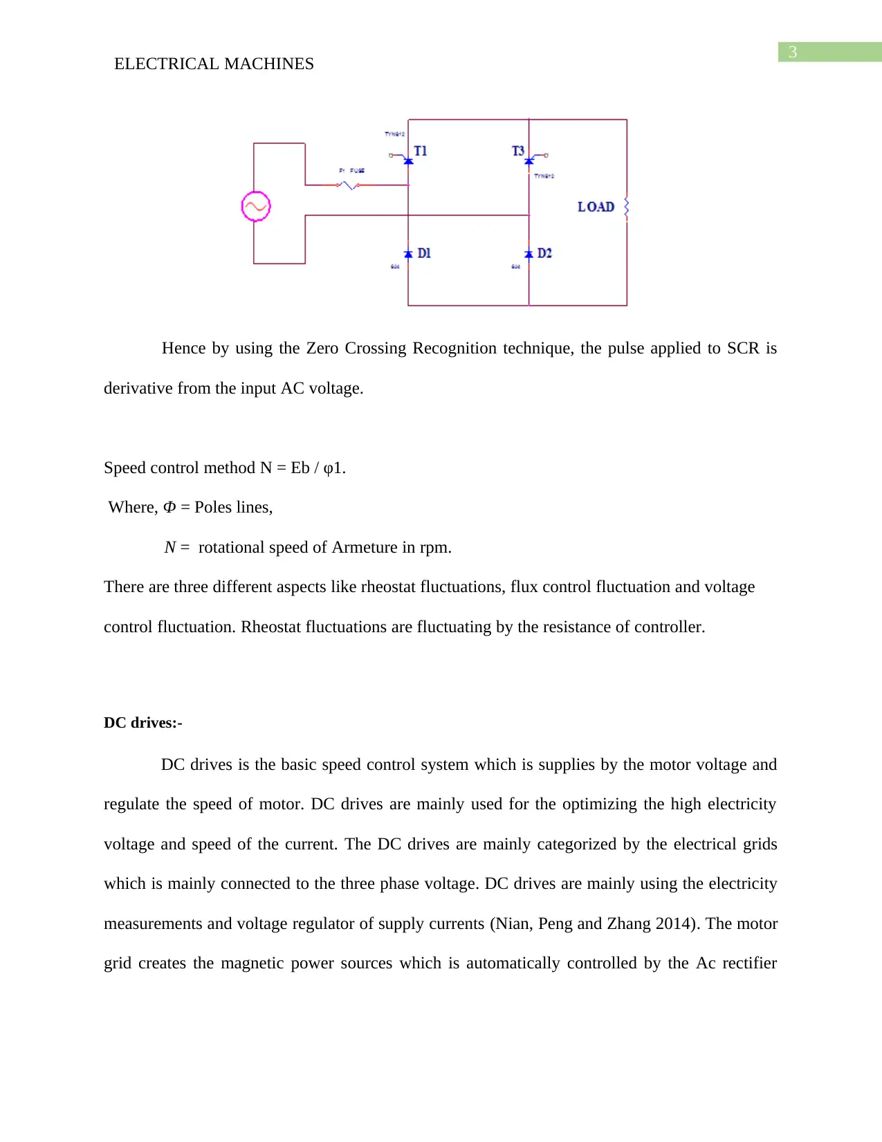
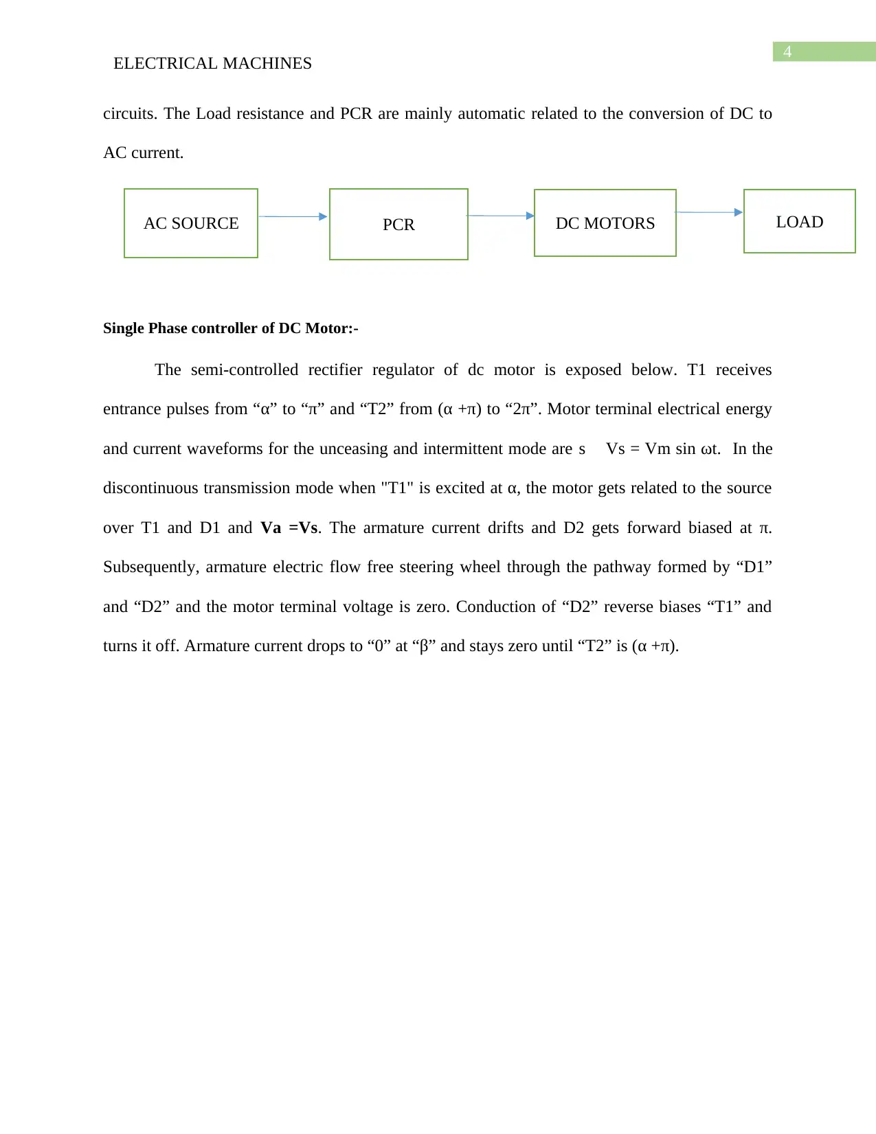
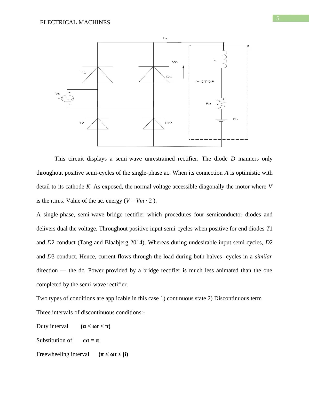
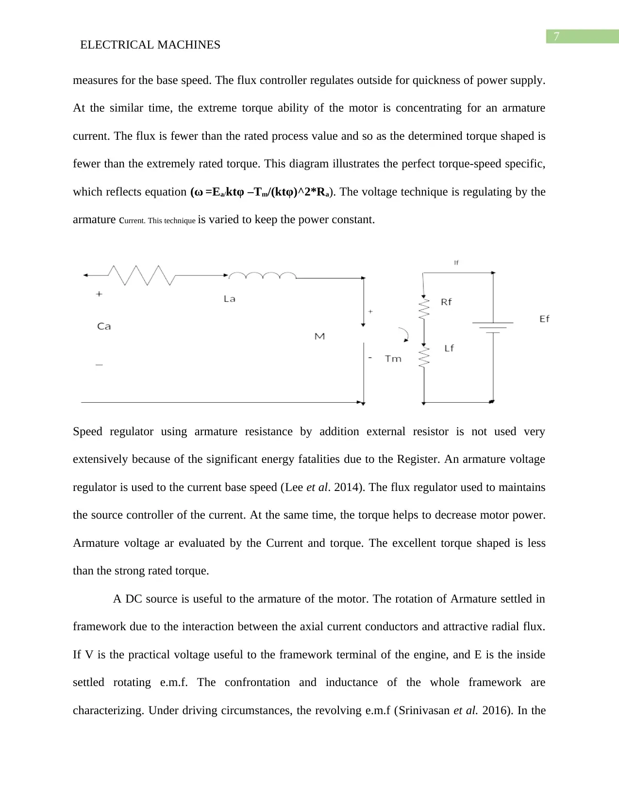
This report provides a comprehensive overview of electrical machines, focusing on single-phase rectifiers, DC drives, and DC motor control. The introduction defines DC servo motors and their applications, highlighting the importance of armature current and field control. The discussion section delves into single-phase rectifiers, explaining their function in converting AC to DC, and explores different speed control methods for DC motors. The report further examines DC drives, their categorization, and their role in optimizing voltage and speed. A significant portion is dedicated to single-phase controllers of DC motors, including semi-controlled rectifier regulators and their operational modes. It also covers armature control methods, comparing armature resistance control, and armature voltage control, and the impact of external resistors. The conclusion summarizes the key findings and emphasizes the functionality of single-phase rectifiers and their applications in electrical machines. The report references several research papers to support its analysis.
Document Page
Running head: ELECTRICAL MACHINES
ELECTRICAL MACHINES
Name of the Student:
Name of the University:
Author Note:
tabler-icon-diamond-filled.svg

Paraphrase This Document

Need a fresh take? Get an instant paraphrase of this document with our AI Paraphraser
Document Page
1
ELECTRICAL MACHINES
Table of Contents
Introduction:-...................................................................................................................................2
Discussion:-.....................................................................................................................................2
Single phase rectifier:-.................................................................................................................2
DC drives:-...............................................................................................................................3
Single Phase controller of DC Motor:-....................................................................................4
Armature Control:-....................................................................................................................10
Conclusion:-...................................................................................................................................12
References:-...................................................................................................................................13
Document Page
2
ELECTRICAL MACHINES
Introduction:-
DC servo motor is the one types of motor which is controlled by the power system. DC
servo motor is mainly identify the structure which can be realized by the system controller
design. There are different types of servo motor are there like magnet motor, brush less motor,
separate excited motor. DC servo motors are controlling the field current which is recognized by
the armature current (Natarajan 2016). DC servo motors are mainly depends on the different
types of applications and this types of applications are saturated by the magnetic power and
armature current. When the DC servo motors are powered by the electric sources then the field
controller are saturated. The range of the current source is constant and armature voltage are
shifted by the change of torque. Single phase rectifier are mainly depended on the two types of
energy flows one is positive and another is negative. In a speed generator there are important to
present the perfect approaches of the high controller generator and deliver the full torques of full
wave rectifier. The armature current are produces for high gain resistance and ripple factor which
is important for the harmonic shifting.
Discussion:-
Single phase rectifier:-
In a single phase rectifier is the one types of current flow which is limited to the one
single direction. The Alternative waveforms can passes through the diode which can efficient to
the different voltage source and average load. Two single wave rectifier contains to the diode
process and analog semi sequence voltage converter.
Document Page
3
ELECTRICAL MACHINES
Hence by using the Zero Crossing Recognition technique, the pulse applied to SCR is
derivative from the input AC voltage.
Speed control method N = Eb / φ1.
Where, Φ = Poles lines,
N = rotational speed of Armeture in rpm.
There are three different aspects like rheostat fluctuations, flux control fluctuation and voltage
control fluctuation. Rheostat fluctuations are fluctuating by the resistance of controller.
DC drives:-
DC drives is the basic speed control system which is supplies by the motor voltage and
regulate the speed of motor. DC drives are mainly used for the optimizing the high electricity
voltage and speed of the current. The DC drives are mainly categorized by the electrical grids
which is mainly connected to the three phase voltage. DC drives are mainly using the electricity
measurements and voltage regulator of supply currents (Nian, Peng and Zhang 2014). The motor
grid creates the magnetic power sources which is automatically controlled by the Ac rectifier
tabler-icon-diamond-filled.svg

Paraphrase This Document

Need a fresh take? Get an instant paraphrase of this document with our AI Paraphraser
Document Page
4
ELECTRICAL MACHINES
circuits. The Load resistance and PCR are mainly automatic related to the conversion of DC to
AC current.
Single Phase controller of DC Motor:-
The semi-controlled rectifier regulator of dc motor is exposed below. T1 receives
entrance pulses from “α” to “π” and “T2” from (α +π) to “2π”. Motor terminal electrical energy
and current waveforms for the unceasing and intermittent mode are s Vs = Vm sin ωt. In the
discontinuous transmission mode when "T1" is excited at α, the motor gets related to the source
over T1 and D1 and Va =Vs. The armature current drifts and D2 gets forward biased at π.
Subsequently, armature electric flow free steering wheel through the pathway formed by “D1”
and “D2” and the motor terminal voltage is zero. Conduction of “D2” reverse biases “T1” and
turns it off. Armature current drops to “0” at “β” and stays zero until “T2” is (α +π).
AC SOURCE PCR DC MOTORS LOAD
Document Page
5
ELECTRICAL MACHINES
This circuit displays a semi-wave unrestrained rectifier. The diode D manners only
throughout positive semi-cycles of the single-phase ac. When its connection A is optimistic with
detail to its cathode K. As exposed, the normal voltage accessible diagonally the motor where V
is the r.m.s. Value of the ac. energy (V = Vm / 2 ).
A single-phase, semi-wave bridge rectifier which procedures four semiconductor diodes and
delivers dual the voltage. Throughout positive input semi-cycles when positive for end diodes T1
and D2 conduct (Tang and Blaabjerg 2014). Whereas during undesirable input semi-cycles, D2
and D3 conduct. Hence, current flows through the load during both halves- cycles in a similar
direction — the dc. Power provided by a bridge rectifier is much less animated than the one
completed by the semi-wave rectifier.
Two types of conditions are applicable in this case 1) continuous state 2) Discontinuous term
Three intervals of discontinuous conditions:-
Duty interval (α ≤ ωt ≤ π)
Substitution of ωt = π
Freewheeling interval (π ≤ ωt ≤ β)
Document Page
6
ELECTRICAL MACHINES
iaRa + La ( di a /dt) +E = 0
So, in a subject to a (π) the equations are
Ia (ωt)= Vm/Z[sin φ* e-(ωt-π)cot φ –sin ( α-φ).e-(ωt-α)cot φ] - E/Ra[1-e-(ωt-α)cot φ] ( for π ≤ ωt ≤β)
Zero interval is applicable. Then ia (β)=0 so,
eβcotφ= Ra Vm [sin φ e πcotφ – sin (α-φ)e αcotφ]+ e αcotφ
β can be evaluated by this solution so,
Va = 1/π [ πα Vm sin ωt d(ωt)+ ∫π+α β Ed (ωt)]
= (Vm (1+cosα) +(π+α-β)*E)/π
So final equation of a discontinuous condition is
Similarly continuous condition also
From the equation, it is perfect that hustle can measure by fluctuating three parameters,
namely, φ, Ra, Ea. The three procedures of speed regulator are Armature resistance controlled.
Armature controlled Flux controlled. Adding outside controller to the DC drive to regulator the
speed of DC motor is not a fit practice as a considerable portion of energy get loosed in terms of
temperature due to the outside regulator Rext (Son and Ha 2014). Armature voltage mainly
ωmc = (Ra/K * Vm /Z [sin φ * e^-α cotφ – sin (α-φ)e ^-πcotφ] ) /
1-e^-π cot φ
tabler-icon-diamond-filled.svg

Paraphrase This Document

Need a fresh take? Get an instant paraphrase of this document with our AI Paraphraser
Document Page
7
ELECTRICAL MACHINES
measures for the base speed. The flux controller regulates outside for quickness of power supply.
At the similar time, the extreme torque ability of the motor is concentrating for an armature
current. The flux is fewer than the rated process value and so as the determined torque shaped is
fewer than the extremely rated torque. This diagram illustrates the perfect torque-speed specific,
which reflects equation =Ea/ktφ –Tm/(ktφ)^2*Ra). The voltage technique is regulating by the
armature current. This technique is varied to keep the power constant.
Speed regulator using armature resistance by addition external resistor is not used very
extensively because of the significant energy fatalities due to the Register. An armature voltage
regulator is used to the current base speed (Lee et al. 2014). The flux regulator used to maintains
the source controller of the current. At the same time, the torque helps to decrease motor power.
Armature voltage ar evaluated by the Current and torque. The excellent torque shaped is less
than the strong rated torque.
A DC source is useful to the armature of the motor. The rotation of Armature settled in
framework due to the interaction between the axial current conductors and attractive radial flux.
If V is the practical voltage useful to the framework terminal of the engine, and E is the inside
settled rotating e.m.f. The confrontation and inductance of the whole framework are
characterizing. Under driving circumstances, the revolving e.m.f (Srinivasan et al. 2016). In the
Document Page
8
ELECTRICAL MACHINES
equation "E" is continuously competing with the practical voltage "V". And for this purpose, it is
mentioning too as "back e.m.f" for existing to be involuntary in the motor, "V" must be better
than "E". And the armature circuit energy calculation being given by
V= E + Iara +L dIa/dt
This equation signifies the inductive current drop due to framework self-inductance. This
voltage is relative to the rate of modification of existing, so under stable state circumstances, the
term will be nothing and can be ignored. Under stable state-condition, the armature current (I) is
constant, and Equation simplifies to
V=E+IaRa
The motor rear emf is given by
Eb=φNZ/60(P/A)v
φ is flux pole
N is speed in rpm.
Z is a number of armature.
A is a figure of parallel paths in the armature.
Therefore for a given DC machine
Eb=(ZP/60A) φN v
Eb=KaφN
Where 60/2π *ωm substitute in Equation
Eb=(ZP/60A) φ(60/2 π)
Eb=(ZP/2 Πa)φ ωm =(ZP/2 ΠA) φIa
Eb=Kaφ ωm (6)
Document Page
9
ELECTRICAL MACHINES
The torque developed by armature is given by
Ta=φ Z Ia/2π(P/A) N-m
Where,
Ka= (ZP/2 πA
Ta=KaφIa=T
Expression 2:-
Ia=(V-E/Ra)
Substituting
Ta=Kaφ(V-E/Ra)
Again Substituting
Ta=Kaφ[V-Kaφ ωm/Ra]
Rearranging the equations
ωm=v/Kaφ-Ra/(Kaφ)^2*Ta
The speed control relationship of Ta/Kaφ this relationship can be replaced by Ia
ωm=V/Kaφ-Ra Ia/(Kaφ)
A perfect DC resource is favoured a semi wave converter for field circuit of semi-wave
converter energy otherwise the magnetic fatalities of the motor intensification due to
extraordinary current content in the field excitation electricity (Dahbi et al. 2014). An
unconnectedly excited DC motor fed whole single phases emf converter is highlighting. An ideal
DC source is choosing over semi wave converter for field route of semi-wave converter drive
otherwise the magnetic fatalities of the motor upsurge due to high wave satisfied in the ground
excitation current. A distinctly excited DC motor nourished through single-phase magnetic field
converter is describing in the diagram. This converter also compromises one quadrant energy.
tabler-icon-diamond-filled.svg

Paraphrase This Document

Need a fresh take? Get an instant paraphrase of this document with our AI Paraphraser
Document Page
10
ELECTRICAL MACHINES
Armature Control:-
Relative DC motor power supply can be derive the back electromagnetic force and that is
called back electromagnetic field.
(Eb = V - IaRa.)
Armature regulator is the conventional energy which is used as an actuator of electrical
source and mechanical energy. There are two methods of DC motors are Field regulate DC
motor and Armature control DC motor. For an armature control the flux rate is constant and used
a linear motor operations (Krishnan 2017). Complete electronic designs can regulate the
electrically powered speed by adjusting the source current realistic to the motor source frame and
other the current. There are some negative feedback and which is applicable to the linear current.
In a DC servo motor the standard armature are broadly used in the initial techniques of
electromagnetic voltage and primary transient responses.
Document Page
11
ELECTRICAL MACHINES
DC motors can be tracks from direct current Source if obtainable or from ac. Supply
later, it has been transformed into dc (Rajesh and Singh 2014). Rectifier supply can be measured
by the full-wave or half-wave .The AC engines can be route on the motor power system. And
this system Supply on the direct current source.
DC source and armature current are routing by the power supply. Power source can be
transform with the help of a thyristor chopper circuit which can be completed to intersect the
direct source current. If direct current the power Supply is not available. It can attain from the
available AC. Supply with the help of uncontrolled rectifiers using only diodes and not thyristor.
Conclusion:-
During the positive half cycle, when the subordinate power source of the higher end is
optimistic with approval to the low term and the diode is below forward bias disorder. During the
semi-cycles, the input voltage is functional. The load resistance of the diode is expected to be
zero. The wave procedures of output current and voltage are similar to that of the AC input
voltage. Through the negative semi cycle, the energy and flow across the load residues zero. The
chevron_up_icon
1 out of 15
circle_padding
hide_on_mobile
zoom_out_icon
[object Object]