Phoenix Air Solutions: Outrigger Undercarriage Fork Failure Analysis
VerifiedAdded on 2022/08/20
|14
|2728
|13
Report
AI Summary
This report, prepared for Phoenix Air Solutions, investigates the premature failure of outrigger undercarriage forks in Harrier T Mk.4 aircraft. It begins with a material analysis, identifying titanium alloys as a suitable alternative and calculating maximum loads. The report then explores non-destructive testing (NDT) methods, specifically ultrasonic testing, dye penetrant inspection, and eddy current testing, to detect cracks. Finally, it proposes additive manufacturing as a solution, suggesting the use of commercially pure titanium and Ti-6Al-4V alloy for production. The report includes graphical analyses, reference tables, diagrams, and load-extension curves to support its findings and recommendations, aiming to provide Phoenix Air Solutions with insights into component failure and potential solutions.
AEROSPACE ENGINEERING
By Name
Course
Instructor
Institution
Location
Date
By Name
Course
Instructor
Institution
Location
Date
Paraphrase This Document
Need a fresh take? Get an instant paraphrase of this document with our AI Paraphraser
TASK 1
Considering that there are ranges of alloys and grades of titanium which are available for the
design work, it is basically possible for the design process to be guided by having selection of
combination of the appropriate properties both for the use as well as fabrication.
In the case of titanium, grades 1,2,3,4 are commercially pure ones. They are usually used purely
for resistance to corrosion. The hardness and strength increases as the grade increases. The
ductility however will reduce as the grade number increases.
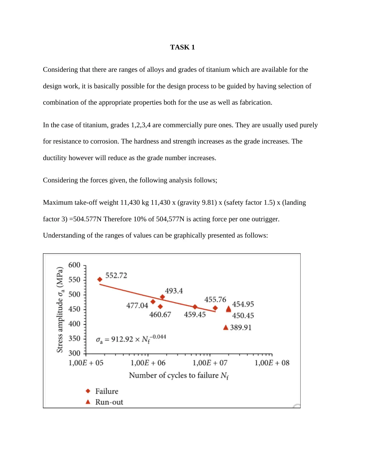
Considering the forces given, the following analysis follows;
Maximum take-off weight 11,430 kg 11,430 x (gravity 9.81) x (safety factor 1.5) x (landing
factor 3) =504.577N Therefore 10% of 504,577N is acting force per one outrigger.
Understanding of the ranges of values can be graphically presented as follows:
Considering that there are ranges of alloys and grades of titanium which are available for the
design work, it is basically possible for the design process to be guided by having selection of
combination of the appropriate properties both for the use as well as fabrication.
In the case of titanium, grades 1,2,3,4 are commercially pure ones. They are usually used purely
for resistance to corrosion. The hardness and strength increases as the grade increases. The
ductility however will reduce as the grade number increases.
Considering the forces given, the following analysis follows;
Maximum take-off weight 11,430 kg 11,430 x (gravity 9.81) x (safety factor 1.5) x (landing
factor 3) =504.577N Therefore 10% of 504,577N is acting force per one outrigger.
Understanding of the ranges of values can be graphically presented as follows:
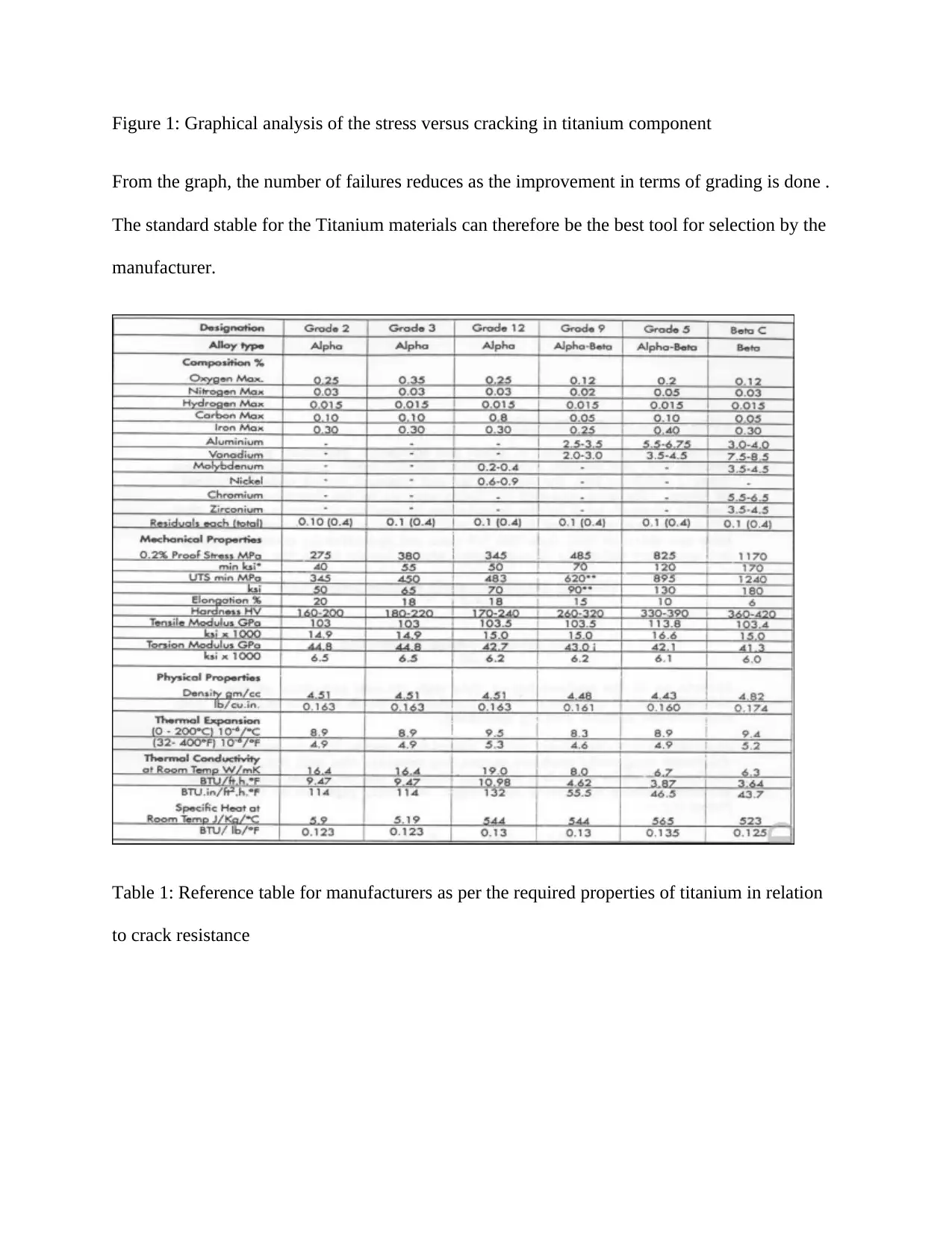
Figure 1: Graphical analysis of the stress versus cracking in titanium component
From the graph, the number of failures reduces as the improvement in terms of grading is done .
The standard stable for the Titanium materials can therefore be the best tool for selection by the
manufacturer.
Table 1: Reference table for manufacturers as per the required properties of titanium in relation
to crack resistance
⊘ This is a preview!⊘
Do you want full access?
Subscribe today to unlock all pages.
Trusted by 1+ million students worldwide
TASK 2
Non Destructive Testing
Non-destructive methods which are commonly refered to as NDTs are basically testing as well as
analysis techniques which are utilized by the industries in the evaluation of the material
properties, structure as well as component for differences in characteristics or defects in welding
and discontinuities without necessarily causing further damage to the part or parts considered to
be original. It is also called Non-destructive examination (NDE), Non-Destructive Evaluation
(NDE) or Non-destructive Inspection (NDI).In order to effectively detect the cracks, several
NDTs will be utilized.
(1) Ultrasonic Testing
Ultrasonic nondestructive testing as commonly refered to as UT. It is a method which can be
potentially used in characterizing the internal structure or just thickness of a test piece through
the use of sound waves with very high frequency. The frequencies of sound which are used in
this type of testing are usually much higher than the limit of hearing in human beings. The
industrial application of this type of the NDT focuses on the materials like plastics, composites,
ceramics and metals. In regard to the material component which was under the study on the
outrigger undercarriage fork, this particular NDT will be most recommended particularly for the
invisible cracks (Huang et al.2016).
Standard Procedure
It is important to note that high frequency sound waves are usually very directional. This implies
that they will basically travel through a medium like plastic or metal until that point they will
Paraphrase This Document
Need a fresh take? Get an instant paraphrase of this document with our AI Paraphraser
encounter a boundary that has another medium like air-a point bat which they will reflect back to
their original source. Through the analysis of such kinds of the reflections, it will be possible to
exactly find or trace the evidences of the cracks as well as other internal flaws which may be
hidden (Nasserrafi et al.2018). During this particular process of testing, an ultrasonic transducer
will be connected to the machine which is being used for the processes of diagnosis. This
transducer will then be passed over the on the outrigger undercarriage fork which is being
inspected.
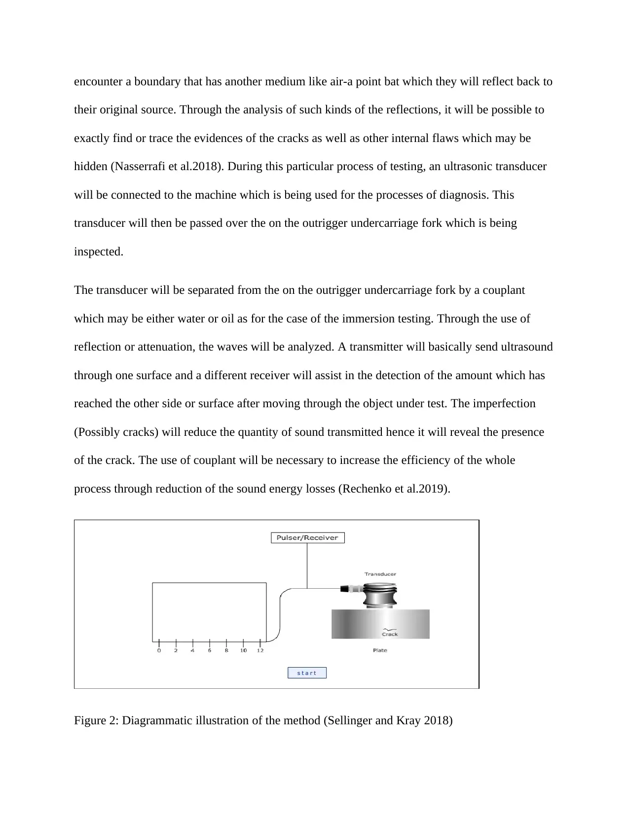
The transducer will be separated from the on the outrigger undercarriage fork by a couplant
which may be either water or oil as for the case of the immersion testing. Through the use of
reflection or attenuation, the waves will be analyzed. A transmitter will basically send ultrasound
through one surface and a different receiver will assist in the detection of the amount which has
reached the other side or surface after moving through the object under test. The imperfection
(Possibly cracks) will reduce the quantity of sound transmitted hence it will reveal the presence
of the crack. The use of couplant will be necessary to increase the efficiency of the whole
process through reduction of the sound energy losses (Rechenko et al.2019).
Figure 2: Diagrammatic illustration of the method (Sellinger and Kray 2018)
their original source. Through the analysis of such kinds of the reflections, it will be possible to
exactly find or trace the evidences of the cracks as well as other internal flaws which may be
hidden (Nasserrafi et al.2018). During this particular process of testing, an ultrasonic transducer
will be connected to the machine which is being used for the processes of diagnosis. This
transducer will then be passed over the on the outrigger undercarriage fork which is being
inspected.
The transducer will be separated from the on the outrigger undercarriage fork by a couplant
which may be either water or oil as for the case of the immersion testing. Through the use of
reflection or attenuation, the waves will be analyzed. A transmitter will basically send ultrasound
through one surface and a different receiver will assist in the detection of the amount which has
reached the other side or surface after moving through the object under test. The imperfection
(Possibly cracks) will reduce the quantity of sound transmitted hence it will reveal the presence
of the crack. The use of couplant will be necessary to increase the efficiency of the whole
process through reduction of the sound energy losses (Rechenko et al.2019).
Figure 2: Diagrammatic illustration of the method (Sellinger and Kray 2018)
Why it is used/ Advantages
There is very minimal separation of parts
This particular method is sensitive to both subsurface and surface discontinuities
The penetration depth is usually superior as opposed to other methods of NDTs
It is highly accurate as far as the detection or determination of the position of the reflector
is concerned as well as shape and size estimation
(2) Dye Penetrant Inspection
Dye Penetrant Inspection is also known as Liquid Penetrant Inspection (LPI). This particular
NDT is used in the detection of the cracks on surfaces which have not been painted. It is another
potential method that could be used in the detection of the cracks on the outrigger undercarriage
fork.
Standard Procedure
Pre-cleaning
The surface of the outrigger undercarriage fork will be cleaned first to ensure that traces of dirt,
paint, grease, oil and any other similar elements are properly removed. This is because they may
have the potential to keep the penetrant away from the defects. The processes of cleaning can be
done by the use of the suitable solvents (Ikumapayi and Akinlabi 2019).
Applications of the penetrant
⊘ This is a preview!⊘
Do you want full access?
Subscribe today to unlock all pages.
Trusted by 1+ million students worldwide
The penetrant will then be applied on the surface of the object to be tested (on the outrigger
undercarriage fork). Dwell time of about 30 minutes will be allowed so that it can be soaked into
the flaws (Chandratre and Kathe 2017).
Removal of Excess Penetrant
The penetrant which will be excess should be removed. The processes of the removal will be
achieved by the use of solvent. Considering that solvent remover will be used as well as a lint-
free cloth, the solvent will not be sprayed directly on the surface since it can potentially remove
or affect the amount of penetrant in the flaws.
Application of the developer
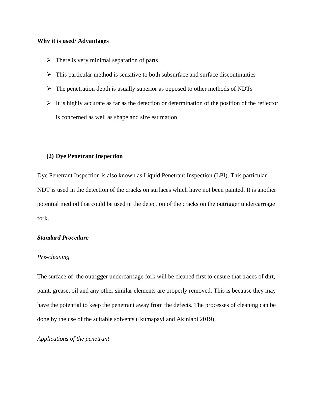
A white developer will be applied to the sample after the removal of the excess penetrant.
Preferably, a white powder developer will be used for proper visibility after considering its
compatibility with the penetrant (Liu et al.2019).
Inspection
There will be use of the visible light that has adequate intensity so as to visibly analyse the
position of the dye penetrant. The inspection process for the surface will be expected to take
about 10 to 15 minutes.
Post cleaning
After the processes of test, the surface of the component will be properly cleaned and defects
will be recorded accordingly. This implies that the post inspection cleaning must be scheduled
for proper results (Kolli and Devaraj 2018).
undercarriage fork). Dwell time of about 30 minutes will be allowed so that it can be soaked into
the flaws (Chandratre and Kathe 2017).
Removal of Excess Penetrant
The penetrant which will be excess should be removed. The processes of the removal will be
achieved by the use of solvent. Considering that solvent remover will be used as well as a lint-
free cloth, the solvent will not be sprayed directly on the surface since it can potentially remove
or affect the amount of penetrant in the flaws.
Application of the developer
A white developer will be applied to the sample after the removal of the excess penetrant.
Preferably, a white powder developer will be used for proper visibility after considering its
compatibility with the penetrant (Liu et al.2019).
Inspection
There will be use of the visible light that has adequate intensity so as to visibly analyse the
position of the dye penetrant. The inspection process for the surface will be expected to take
about 10 to 15 minutes.
Post cleaning
After the processes of test, the surface of the component will be properly cleaned and defects
will be recorded accordingly. This implies that the post inspection cleaning must be scheduled
for proper results (Kolli and Devaraj 2018).
Paraphrase This Document
Need a fresh take? Get an instant paraphrase of this document with our AI Paraphraser
Figure 3: Diagrammatic illustrations of the process (Smurov et al. 2017)
Why it is used/ Advantages
This method is relatively inexpensive
It is usually possible for to perform very rapid or faster processes of detection on larger
surfaces
The sensitivity is usually high
Allow for the detection of both metallic and non-metallic components
(3) Eddy Current Testing
This is an inspection method which can also be used in the detection of the corrosion effects as
well as cracks on the surface of the objects under the tests. This particular method is usually
known to depend on the characteristics of the materials known as electro-magnetic induction
ranges (Jovanović 2016).
Standard Procedure
In this concept, when there is passage of ac or alternating current through a conductor
particularly a copper coil then there will be development of the magnetic field around the coil.
The field is known to expand as well as contract as the ac current rises. In the event that coil is
brought closer to another current object or conductor, the will be permeating action by the
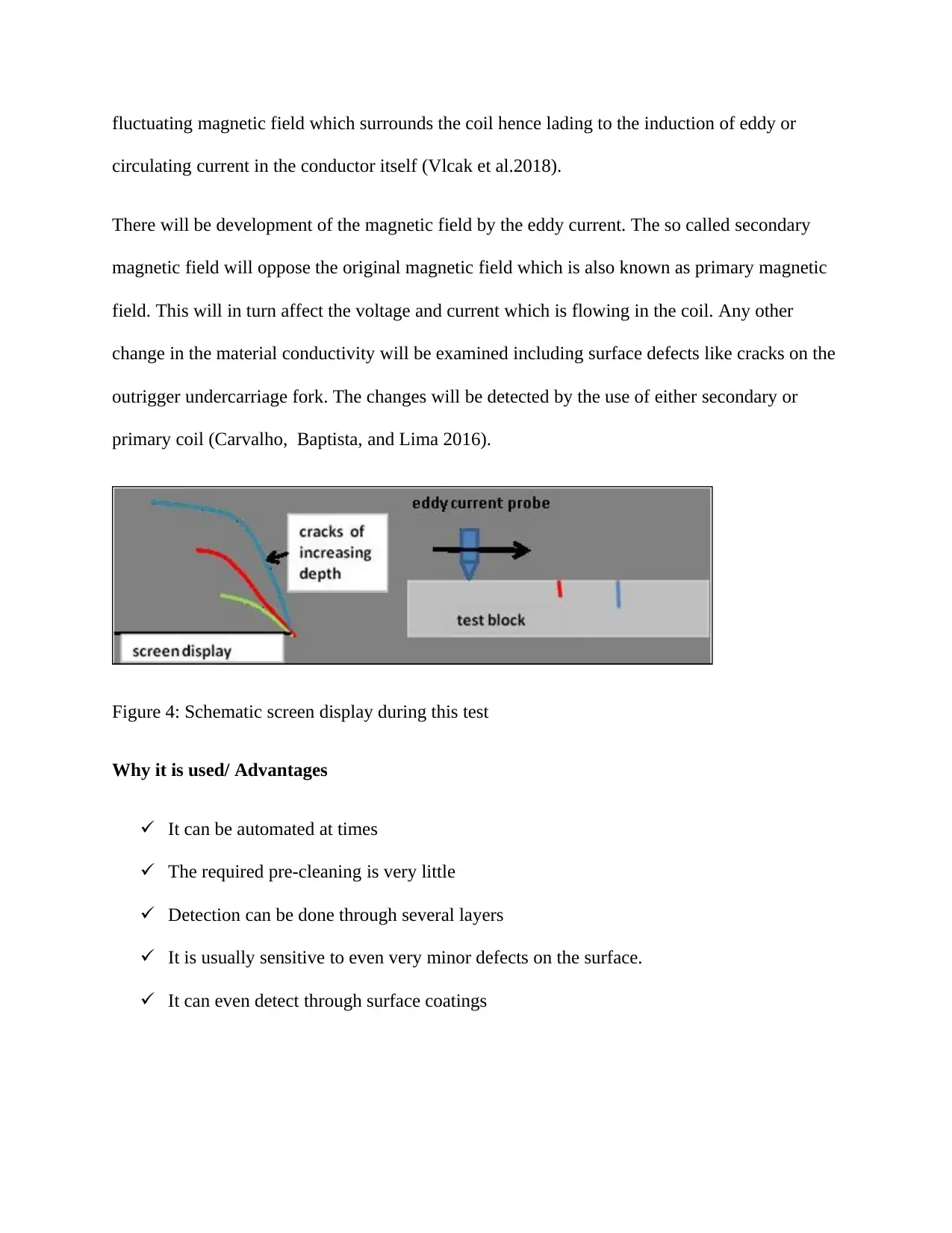
fluctuating magnetic field which surrounds the coil hence lading to the induction of eddy or
circulating current in the conductor itself (Vlcak et al.2018).
There will be development of the magnetic field by the eddy current. The so called secondary
magnetic field will oppose the original magnetic field which is also known as primary magnetic
field. This will in turn affect the voltage and current which is flowing in the coil. Any other
change in the material conductivity will be examined including surface defects like cracks on the
outrigger undercarriage fork. The changes will be detected by the use of either secondary or
primary coil (Carvalho, Baptista, and Lima 2016).
Figure 4: Schematic screen display during this test
Why it is used/ Advantages
It can be automated at times
The required pre-cleaning is very little
Detection can be done through several layers
It is usually sensitive to even very minor defects on the surface.
It can even detect through surface coatings
⊘ This is a preview!⊘
Do you want full access?
Subscribe today to unlock all pages.
Trusted by 1+ million students worldwide
Task 3
Titanium as well as alloy made from titanium have been identified by the researchers as one of
the best metals in the engineering applications. This is due to some of its beneficial properties
including higher mechanical strength as well as relatively reduced density. The metal is generally
attractive due to the fact that it has a proper or very excellent resistance to rust even in the
extreme environments. Titanium could be an alternative metal which could be used in the
production of the parts the parts of the aircraft particularly the outrigger undercarriage fork. The
choice of this particular metal as an alternative is due to its high tensile strength to density ratio,
higher resistance to corrosion and the capacity of withstanding very high temperatures without
necessarily undergoing creeping (Froend et al.2017).
The low density of the metal will definitely translate into very little consumptions of fuels by the
aircrafts as the operations intensify. Reduced fuel consumption will be due to the fact that the
plane will be of less or reduced weight. It is import ant to note that this concept can be utilized
and advantage taken so that additional liters of fuel can be carried by the plane hence choice will
be appropriate. The aircraft with a lot of fuel on board will be able to cover very longer distances
or simply increased range of the aircraft (Hammer and Muttur 2016). Finally , research work has
established that Titanium together with its alloys have delayed crack initiation when subjected to
loading ..
Paraphrase This Document
Need a fresh take? Get an instant paraphrase of this document with our AI Paraphraser
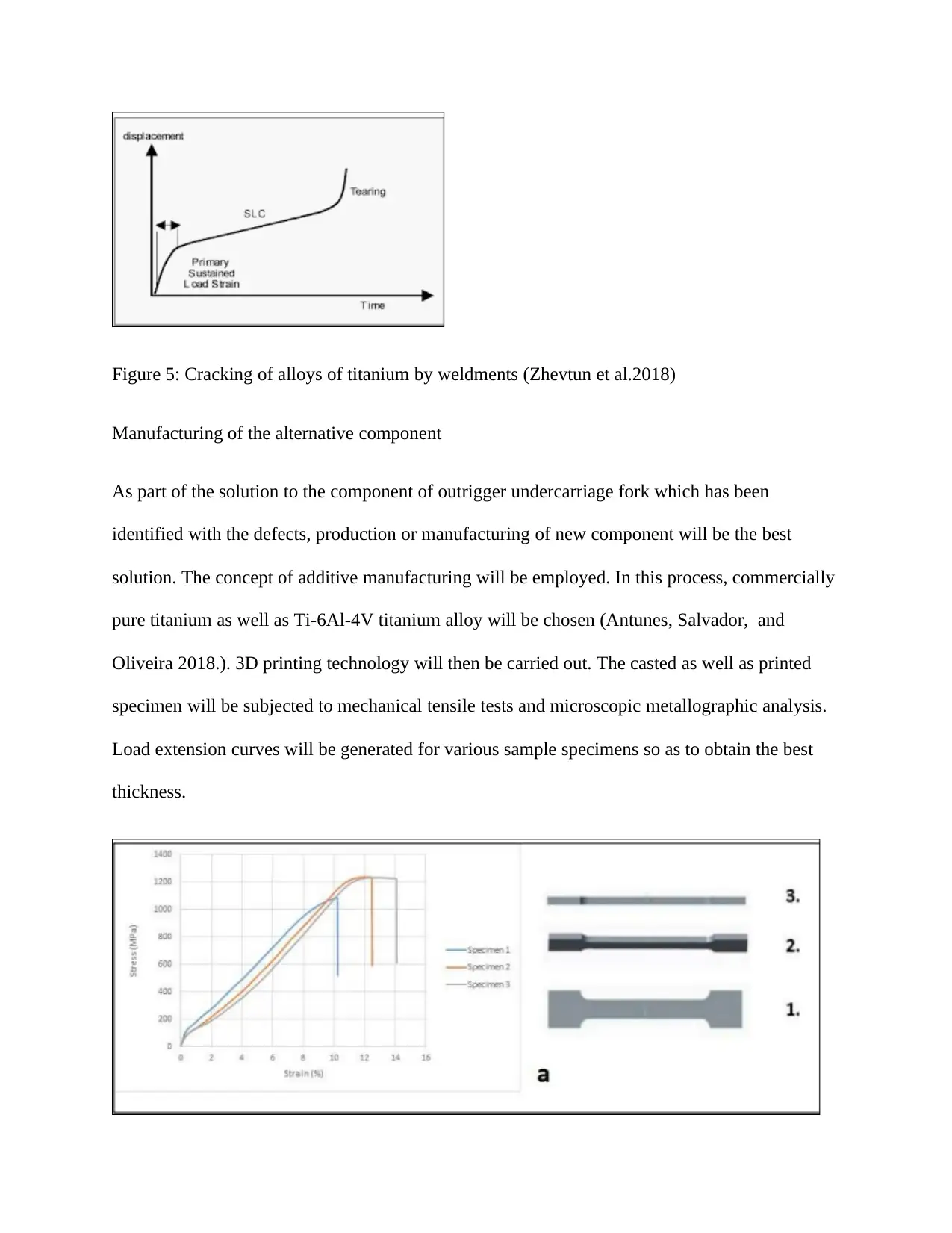
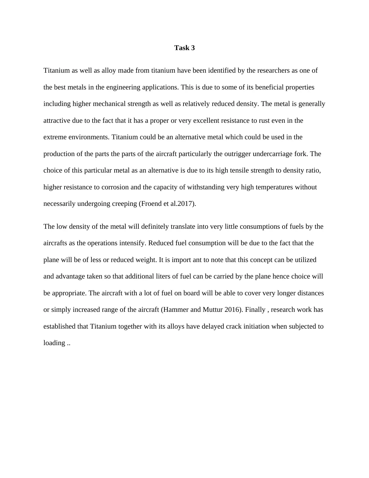
Figure 5: Cracking of alloys of titanium by weldments (Zhevtun et al.2018)
Manufacturing of the alternative component
As part of the solution to the component of outrigger undercarriage fork which has been
identified with the defects, production or manufacturing of new component will be the best
solution. The concept of additive manufacturing will be employed. In this process, commercially
pure titanium as well as Ti-6Al-4V titanium alloy will be chosen (Antunes, Salvador, and
Oliveira 2018.). 3D printing technology will then be carried out. The casted as well as printed
specimen will be subjected to mechanical tensile tests and microscopic metallographic analysis.
Load extension curves will be generated for various sample specimens so as to obtain the best
thickness.
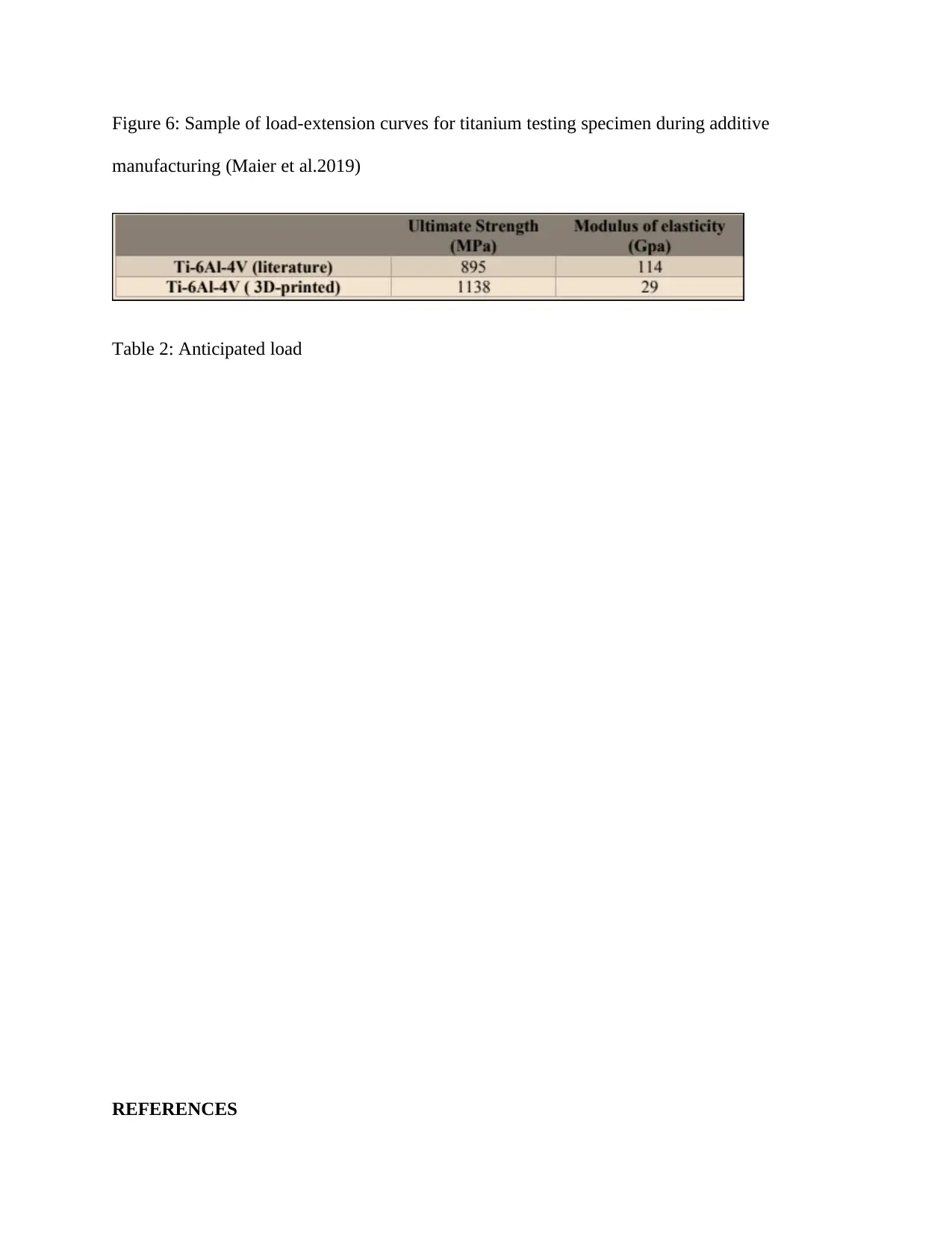
Figure 6: Sample of load-extension curves for titanium testing specimen during additive
manufacturing (Maier et al.2019)
Table 2: Anticipated load
REFERENCES
manufacturing (Maier et al.2019)
Table 2: Anticipated load
REFERENCES
⊘ This is a preview!⊘
Do you want full access?
Subscribe today to unlock all pages.
Trusted by 1+ million students worldwide
1 out of 14


Your All-in-One AI-Powered Toolkit for Academic Success.
+13062052269
info@desklib.com
Available 24*7 on WhatsApp / Email
![[object Object]](/_next/static/media/star-bottom.7253800d.svg)
Unlock your academic potential
Copyright © 2020–2026 A2Z Services. All Rights Reserved. Developed and managed by ZUCOL.