Electromagnetic Induction Experiment: Physics Lab Proposal Analysis

Verified

Added on  2023/02/01

|7
|1119
|86
Practical Assignment
AI Summary
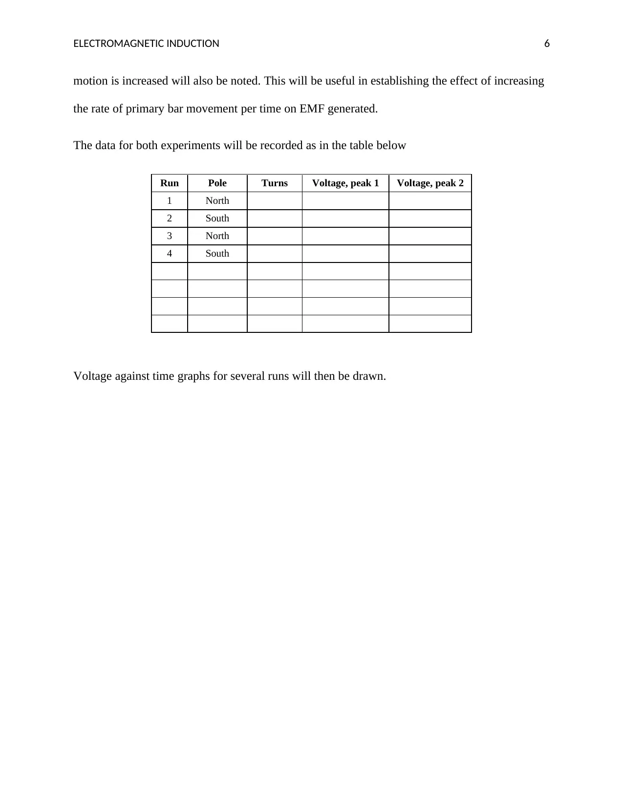
This document is a physics lab proposal that delves into the principles of electromagnetic induction, a foundational concept in electrical production and transmission. The proposal outlines two main experiments designed to qualitatively study Faraday's and Lenz's laws. The first part involves using a bar magnet to induce voltage (EMF) in a coil, observing the effects of changing magnetic flux and varying the magnet's motion. The second part utilizes an electromagnet to generate an induced EMF, with similar observations and data recording. The methodology includes detailed procedures, apparatus descriptions (galvanometer, coils, magnets, DC power supply), and data collection techniques, aiming to provide a clear understanding of electromagnetic induction and its underlying principles.
Document Page
Running head: ELECTROMAGNETIC INDUCTION
1
Physics lab proposal: Electromagnetic Induction
Student
Institutional affiliation
tabler-icon-diamond-filled.svg

Paraphrase This Document

Need a fresh take? Get an instant paraphrase of this document with our AI Paraphraser
Document Page
ELECTROMAGNETIC INDUCTION 2
Introduction
The reason as to why this topic has been chosen is because it is one of the most important
branches of the study of the behaviour of electricity; induced current production. It is among the
foundations of electrical production and transmission. Michael Faraday found out that whenever
there is a slight alteration in the magnetic flux transient through a loop of wire, then a voltage
(Electromotive Force) is usually induced in the wire. It is from this behaviour that electric motors
derive their mechanical energy that is applied in many areas. The production alternating current
of electricity also applies the knowledge of induction. This laboratory proposal is going to delve
into the production and measurement of the induced EMF using bar magnet and electromagnets.
Theory
This lab is going to be divided into two parts. The first task will be understanding and
proving electromagnetic induction qualitatively. This will be attained by demonstrating how
Lenz’s Law is used. According to Lenz’s Law, an object will produce its own magnetic field that
tries to oppose the magnetic field at which it was introduced (Jefimenko, 2011). The experiment
will then test the measurement of induced voltage (EMF) that is produced by changing the
magnetic flux of a coil.
ΦB=BA 1
Where A is the area of the coil (cross-sectional) and B is the magnetic field
This is because EMF causes the flow of induced current in the circuit. Based on Faraday's
law, the magnitude of the induced voltage (EMF) in a loop is equivalent to the rate of the change
of the magnet flux (ϕB) in the loop with time (t).
Document Page
ELECTROMAGNETIC INDUCTION 3
emf =N ΦB
t = N d ΦB
dt 2
Where
N sum of coils of the conducting loop and ϕB is magnetic flux
The negative sign in equation 2 above is Lenz’s law. It is used to determine the direction of the
EMF induced (Moullin, 2015). The direction of the current is determined by the right-hand rule.
Based on the right-hand rule, if a coil is grasped in the right hand such that the fingers point in
the direction of the current induced in the coil, the thumb will point the North Pole of the
electromagnet.
Apparatus
Galvanometer, Aluminium rod, Iron rod, Primary and secondary coils, Connecting wires, bar
magnet and DC power supply
Objective
The goal of this experiment will be to qualitatively study the Faraday’s and Lenz’s laws
of electromagnetic induction.
Part I
Induction Using A bar Magnet
In this experiment, the EMF (voltage) induced by altering the magnetic flux of a coil is
observed. The garnet flux in this case due to the magnet field of the bar magnet. The connections
will be done as the figure 1 below. The coil (secondary coil) will first be inspected to establish
(note the small holes) the direction of the induced current.
Document Page
ELECTROMAGNETIC INDUCTION 4
Figure 1 Electromagnetic Induction (Moving Magnet)
The deflection of the galvanometer is used to indicate the current flow. By convention, when
current enters the galvanometer through the positive terminal, the pointer deflects to the right.
Using the right-hand rule, the end of the coil representing the north and south poles will be
determined respectively.
Methodology
The bar magnet will be inserted into the coil to cause a change in the magnetic flux. The
result will be an induced voltage across the solenoid. The EMF causes the induced current to
flow in the loop. The current induced generates an induced magnetic field in the direction that is
obtained by the right-hand rule. The bar will be inserted slowly and observations of the
galvanometer deflection made; during motion and when motion ceases. These steps will be
repeated a couple of times. The rate at which the bar is moved will also be varied and
observations made. Drawings will be made after every observation. The magnet pole will then be
Bar Magnet
Galvanometer
Large Coil
tabler-icon-diamond-filled.svg

Paraphrase This Document

Need a fresh take? Get an instant paraphrase of this document with our AI Paraphraser
Document Page
ELECTROMAGNETIC INDUCTION 5
changed (this time south pole) and the voltage generated will be noted as well. The number of
turns will also be varied to examine its relationship on the voltage produced.
Part II
Induction Using an Electro-Magnet
An electromagnet is made by passing a direct current through the primary loop. The
primary magnet acts as the bar magnet. It has both north and south poles. The equipment will be
connected as in the below figure.
Figure 2 Electromagnetic Induction (Moving electromagnet)
Methodology
After the DC power supply has been turned on, the primary coil will be moved (inserted)
into the secondary coil. Galvanometer deflections will be noted. Theoretically, the deflections
will be small. To increase deflections, a still bar is inserted inside the primary coil to improve the
strength of the electromagnet. Observations on of galvanometer deflections when the rate of
DC Power Supply
Galvanomete
r
Small Coil Large Coil
Document Page
ELECTROMAGNETIC INDUCTION 6
motion is increased will also be noted. This will be useful in establishing the effect of increasing
the rate of primary bar movement per time on EMF generated.
The data for both experiments will be recorded as in the table below
Run Pole Turns Voltage, peak 1 Voltage, peak 2
1 North
2 South
3 North
4 South
Voltage against time graphs for several runs will then be drawn.
Document Page
ELECTROMAGNETIC INDUCTION 7
References
Crowell, B. (2006). Electricity and magnetism. Fullerton, CA: Light and Matter.
Jefimenko, O. D. (2011). Causality, electromagnetic induction, and gravitation: A different
approach to the theory of electromagnetic and gravitational fields. Star City, W. Va:
Electret Scientific Co.
Moullin, E. B. (2015). The Principles of electromagnetism. Oxford: Clarendon Pr.
Sree, H. N. R., Prakash, A., Kothari, D. P., & Institute of Physics (Great Britain),. (2016). The
foundations of electric circuit theory.
chevron_up_icon
1 out of 7
circle_padding
hide_on_mobile
zoom_out_icon
[object Object]