Impact of DTC and FOC on PMSM Performance: A Comparative Study
VerifiedAdded on 2020/01/23
|7
|2597
|54
Report
AI Summary
This report presents a comparative study on the performance of Permanent Magnet Synchronous Motors (PMSM) under Direct Torque Control (DTC) and Field-Oriented Control (FOC). The study utilizes MATLAB/Simulink environment to simulate the PMSM model and evaluate the impact of each control technique on the motor's dynamic behavior. The report includes a mathematical model of PMSM and a brief explanation of the control methods. The simulation results demonstrate that DTC exhibits superior dynamic performance in terms of speed, torque, and current compared to FOC, particularly under various load conditions. The report provides detailed waveform analysis of current, flux, speed, and torque for both control strategies, revealing that DTC offers better transient response, reduced torque ripple, and more stable stator currents. The findings highlight the advantages of DTC in achieving faster response and improved tracking of reference speed. The conclusion emphasizes the practical implications of the study and suggests potential future research directions, such as incorporating Model Predictive Control (MPC) for further performance enhancement.
Impact on the performance of PMSM due to direct torque
control and field-oriented control a comparative study
Abstract— Permanent magnet synchronous engines
(PMSM) can be used specifically set up of the acceptance
engines (I.M) for a few mechanical applications since it is
portrayed by high effectiveness, high power element, and
high power contrasted with I.M. For the most part,
permanent magnet synchronous engines are utilized as a
part of utilizations which require quick torque reaction
and additionally higher-execution operation of the
machine. With a specific end goal to accomplish such
elements, different control strategies including vector
control (VC)/field situated control (FOC) and direct
torque control (DTC) are used. This paper presents
reenactment of these separate strategies to fathom the
effect of every system on element execution of permanent
magnet synchronous engines. MATLAB/Simulink
environment has been utilized to actualize this study under
element reaction. In this paper, the conduct of PMSM will
be concentrated on under the above strategies by utilizing
the Matlab/Simulink environment.
Index Terms— PMSM, direct torque control method,
field oriented control method.
I. INTRODUCTION
In the most recent couple of years, permanent magnet
synchronous engine has picked up a significant consideration
in the enterprises and scholastic world [1]. For all intents and
purposes, PMSM is viewed as more alluring than acceptance
engines concerning high obligation calculate modern
applications, for example, pump, fan, and compressor in light
of its high productivity, subordinate life cycle, high power
figure, and less affectability to supply recurrence and voltage
deviations [2]. In Permanent magnet, synchronous engines the
rotor winding are supplanted by permanent magnets. A
permanent magnet synchronous machine is essentially
customary AC machine with twisting appropriated in the stator
spaces so that the flux made by stator current is around
sinusoidal.
Superior engine control is described by cover turn up the whole
speed scope of the engine, full torque control at zero speed, and
quick increasing speed and deceleration [3]. In such manner,
different techniques have been utilized, for example, vector
control (VC)/field arranged control (FOC) and direct torque
control (DTC). So as to accomplish a decent execution of
permanent magnet synchronous engine. Along these lines, this
paper will reveal insight into dissecting the effect of every
technique on permanent magnet synchronous engine.
MATLAB/Simulink environment will have used to direct this
study. In this paper, a PMSM model is inferred in Section II,
taken after by a brief clarification of FOC, MPC and DTC in
Area III, Section IV shows simulation comes about
.
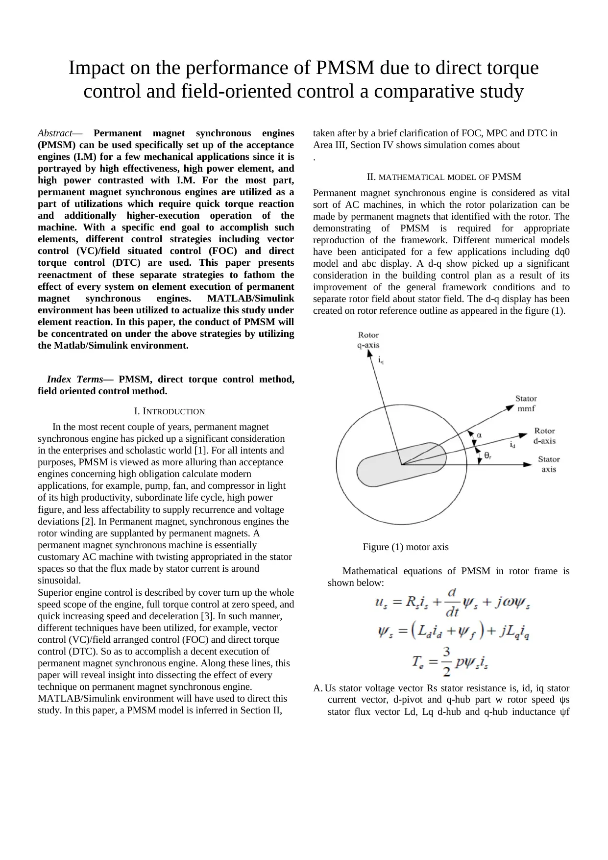
II. MATHEMATICAL MODEL OF PMSM
Permanent magnet synchronous engine is considered as vital
sort of AC machines, in which the rotor polarization can be
made by permanent magnets that identified with the rotor. The
demonstrating of PMSM is required for appropriate
reproduction of the framework. Different numerical models
have been anticipated for a few applications including dq0
model and abc display. A d-q show picked up a significant
consideration in the building control plan as a result of its
improvement of the general framework conditions and to
separate rotor field about stator field. The d-q display has been
created on rotor reference outline as appeared in the figure (1).
Figure (1) motor axis
Mathematical equations of PMSM in rotor frame is
shown below:
A. Us stator voltage vector Rs stator resistance is, id, iq stator
current vector, d-pivot and q-hub part w rotor speed ψs
stator flux vector Ld, Lq d-hub and q-hub inductance ψf
control and field-oriented control a comparative study
Abstract— Permanent magnet synchronous engines
(PMSM) can be used specifically set up of the acceptance
engines (I.M) for a few mechanical applications since it is
portrayed by high effectiveness, high power element, and
high power contrasted with I.M. For the most part,
permanent magnet synchronous engines are utilized as a
part of utilizations which require quick torque reaction
and additionally higher-execution operation of the
machine. With a specific end goal to accomplish such
elements, different control strategies including vector
control (VC)/field situated control (FOC) and direct
torque control (DTC) are used. This paper presents
reenactment of these separate strategies to fathom the
effect of every system on element execution of permanent
magnet synchronous engines. MATLAB/Simulink
environment has been utilized to actualize this study under
element reaction. In this paper, the conduct of PMSM will
be concentrated on under the above strategies by utilizing
the Matlab/Simulink environment.
Index Terms— PMSM, direct torque control method,
field oriented control method.
I. INTRODUCTION
In the most recent couple of years, permanent magnet
synchronous engine has picked up a significant consideration
in the enterprises and scholastic world [1]. For all intents and
purposes, PMSM is viewed as more alluring than acceptance
engines concerning high obligation calculate modern
applications, for example, pump, fan, and compressor in light
of its high productivity, subordinate life cycle, high power
figure, and less affectability to supply recurrence and voltage
deviations [2]. In Permanent magnet, synchronous engines the
rotor winding are supplanted by permanent magnets. A
permanent magnet synchronous machine is essentially
customary AC machine with twisting appropriated in the stator
spaces so that the flux made by stator current is around
sinusoidal.
Superior engine control is described by cover turn up the whole
speed scope of the engine, full torque control at zero speed, and
quick increasing speed and deceleration [3]. In such manner,
different techniques have been utilized, for example, vector
control (VC)/field arranged control (FOC) and direct torque
control (DTC). So as to accomplish a decent execution of
permanent magnet synchronous engine. Along these lines, this
paper will reveal insight into dissecting the effect of every
technique on permanent magnet synchronous engine.
MATLAB/Simulink environment will have used to direct this
study. In this paper, a PMSM model is inferred in Section II,
taken after by a brief clarification of FOC, MPC and DTC in
Area III, Section IV shows simulation comes about
.
II. MATHEMATICAL MODEL OF PMSM
Permanent magnet synchronous engine is considered as vital
sort of AC machines, in which the rotor polarization can be
made by permanent magnets that identified with the rotor. The
demonstrating of PMSM is required for appropriate
reproduction of the framework. Different numerical models
have been anticipated for a few applications including dq0
model and abc display. A d-q show picked up a significant
consideration in the building control plan as a result of its
improvement of the general framework conditions and to
separate rotor field about stator field. The d-q display has been
created on rotor reference outline as appeared in the figure (1).
Figure (1) motor axis
Mathematical equations of PMSM in rotor frame is
shown below:
A. Us stator voltage vector Rs stator resistance is, id, iq stator
current vector, d-pivot and q-hub part w rotor speed ψs
stator flux vector Ld, Lq d-hub and q-hub inductance ψf
Paraphrase This Document
Need a fresh take? Get an instant paraphrase of this document with our AI Paraphraser
permanent magnet flux Te electromagnetic torque p
number of pole sets. Control techniques of PMSM.
permanent magnet synchronous engine can be driven by
utilizing variable recurrence drive that that empower it to keep
running at various speed conditions [4]. Control strategies of
engines can be characterized into two principle classifications
relying upon amounts they control, for example, scalar control
and vector control techniques as delineated underneath:
B. Scalar
This procedure can be utilized to alter the engine recurrence in
the assistance of control the stator voltage adequacy and
recurrence of the separate engine. It has seen that the extent of
the stator voltage as for recurrence must be kept consistent that
is called as V/F control of AC engine drives [5]. This technique
is used in the spots where many engines are driven in parallel
utilizing singular inverter [6].
C. Vector control
This method depends for the most part on the adequacy and
position of the controlled space vector. Such relations are
viewed as viable even in the transient circumstances where
combined with size of the rotor and stator flux point between
them is taken in thought too [6].
1. Field oriented control method
Documented arranged control has been developed in the start
of 1970s. It demonstrates that acceptance engines can be
controlled like energized D.C engine in the different way and
also it added to acquiring a rejuvenation the superior control of
A.C engines. It merits saying that Filed arranged control
method is material to both enlistment and synchronous engines
[7]. The standard operation of vector control method is to
control the torque and stator flux of separate engine
autonomously through affecting the related field arranged
amounts
Figure(2): diagram of Field oriented control method[10]
2. Direct torque control method
Coordinate torque control is the most cutting edge strategy that
in light of field situated control and the immediate restraint plot
has been acknowledged in a modern path by ABB amid 1971-
1985 by Depenbrok [8]. The fundamental idea of this
procedure is to control stator flux and the torque by picking the
voltage space vectors properly, that established strategy is
dependent upon hysteresis controller and also the exchanging
table [9].
Figure(3) diagram of direct torque control method [10].
3. Model predictive control method
Recently, Model prescient control strategy has been utilized in
permanent magnet synchronous engine since it can give
imperative advantages over field-arranged control technique ,
especially with clear controller tuning and requirements
handling[9].the primary standard operation of this technique is
to gauge the behviour of the varibles over a particular time
period rely on upon the framework model.it merits specifying
that all forecast ought to be surveyed rely on upon a component
of the cost. Subsequently,the forecast that can diminish the cost
capacity is chosen. Show prescient control technique has
substaintial highlights including the simple inclustion
constrainnts and nonlinearitites[10].
Figure(4): diagram of Model predictive control method[10]
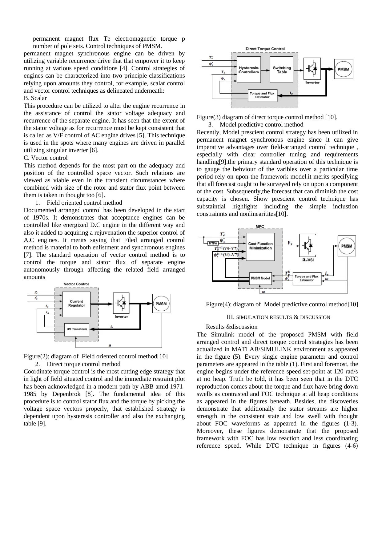
III. SIMULATION RESULTS & DISCUSSION
Results &discussion
The Simulink model of the proposed PMSM with field
arranged control and direct torque control strategies has been
actualized in MATLAB/SIMULINK environment as appeared
in the figure (5). Every single engine parameter and control
parameters are appeared in the table (1). First and foremost, the
engine begins under the reference speed set-point at 120 rad/s
at no heap. Truth be told, it has been seen that in the DTC
reproduction comes about the torque and flux have bring down
swells as contrasted and FOC technique at all heap conditions
as appeared in the figures beneath. Besides, the discoveries
demonstrate that additionally the stator streams are higher
strength in the consistent state and low swell with thought
about FOC waveforms as appeared in the figures (1-3).
Moreover, these figures demonstrate that the proposed
framework with FOC has low reaction and less coordinating
reference speed. While DTC technique in figures (4-6)
number of pole sets. Control techniques of PMSM.
permanent magnet synchronous engine can be driven by
utilizing variable recurrence drive that that empower it to keep
running at various speed conditions [4]. Control strategies of
engines can be characterized into two principle classifications
relying upon amounts they control, for example, scalar control
and vector control techniques as delineated underneath:
B. Scalar
This procedure can be utilized to alter the engine recurrence in
the assistance of control the stator voltage adequacy and
recurrence of the separate engine. It has seen that the extent of
the stator voltage as for recurrence must be kept consistent that
is called as V/F control of AC engine drives [5]. This technique
is used in the spots where many engines are driven in parallel
utilizing singular inverter [6].
C. Vector control
This method depends for the most part on the adequacy and
position of the controlled space vector. Such relations are
viewed as viable even in the transient circumstances where
combined with size of the rotor and stator flux point between
them is taken in thought too [6].
1. Field oriented control method
Documented arranged control has been developed in the start
of 1970s. It demonstrates that acceptance engines can be
controlled like energized D.C engine in the different way and
also it added to acquiring a rejuvenation the superior control of
A.C engines. It merits saying that Filed arranged control
method is material to both enlistment and synchronous engines
[7]. The standard operation of vector control method is to
control the torque and stator flux of separate engine
autonomously through affecting the related field arranged
amounts
Figure(2): diagram of Field oriented control method[10]
2. Direct torque control method
Coordinate torque control is the most cutting edge strategy that
in light of field situated control and the immediate restraint plot
has been acknowledged in a modern path by ABB amid 1971-
1985 by Depenbrok [8]. The fundamental idea of this
procedure is to control stator flux and the torque by picking the
voltage space vectors properly, that established strategy is
dependent upon hysteresis controller and also the exchanging
table [9].
Figure(3) diagram of direct torque control method [10].
3. Model predictive control method
Recently, Model prescient control strategy has been utilized in
permanent magnet synchronous engine since it can give
imperative advantages over field-arranged control technique ,
especially with clear controller tuning and requirements
handling[9].the primary standard operation of this technique is
to gauge the behviour of the varibles over a particular time
period rely on upon the framework model.it merits specifying
that all forecast ought to be surveyed rely on upon a component
of the cost. Subsequently,the forecast that can diminish the cost
capacity is chosen. Show prescient control technique has
substaintial highlights including the simple inclustion
constrainnts and nonlinearitites[10].
Figure(4): diagram of Model predictive control method[10]
III. SIMULATION RESULTS & DISCUSSION
Results &discussion
The Simulink model of the proposed PMSM with field
arranged control and direct torque control strategies has been
actualized in MATLAB/SIMULINK environment as appeared
in the figure (5). Every single engine parameter and control
parameters are appeared in the table (1). First and foremost, the
engine begins under the reference speed set-point at 120 rad/s
at no heap. Truth be told, it has been seen that in the DTC
reproduction comes about the torque and flux have bring down
swells as contrasted and FOC technique at all heap conditions
as appeared in the figures beneath. Besides, the discoveries
demonstrate that additionally the stator streams are higher
strength in the consistent state and low swell with thought
about FOC waveforms as appeared in the figures (1-3).
Moreover, these figures demonstrate that the proposed
framework with FOC has low reaction and less coordinating
reference speed. While DTC technique in figures (4-6)
demonstrates that the individual framework has quick reaction
and great following with reference speed.
PMSM parameters Value Unit
Reference speed 120 Rad/s
Reference torque 150 N.m
Flux 0.887 W.b
Voltage 400 V
Figure (5): PMSM model
The figures underneath demonstrate that execution of
Permanent magnet synchronous engine with DTC and FOC
strategies under various load conditions
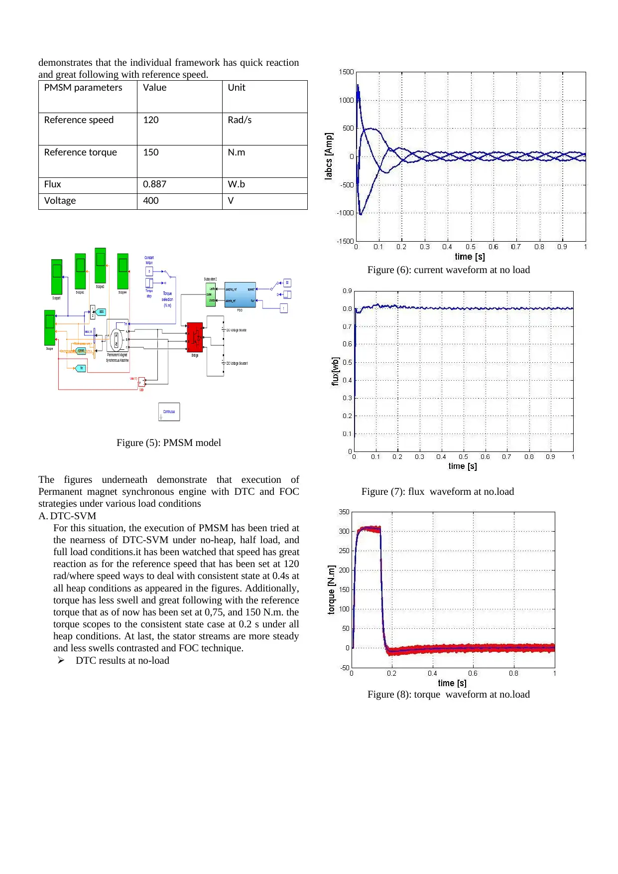
A. DTC-SVM
For this situation, the execution of PMSM has been tried at
the nearness of DTC-SVM under no-heap, half load, and
full load conditions.it has been watched that speed has great
reaction as for the reference speed that has been set at 120
rad/where speed ways to deal with consistent state at 0.4s at
all heap conditions as appeared in the figures. Additionally,
torque has less swell and great following with the reference
torque that as of now has been set at 0,75, and 150 N.m. the
torque scopes to the consistent state case at 0.2 s under all
heap conditions. At last, the stator streams are more steady
and less swells contrasted and FOC technique.
DTC results at no-load
Figure (6): current waveform at no load
Figure (7): flux waveform at no.load
Figure (8): torque waveform at no.load
and great following with reference speed.
PMSM parameters Value Unit
Reference speed 120 Rad/s
Reference torque 150 N.m
Flux 0.887 W.b
Voltage 400 V
Figure (5): PMSM model
The figures underneath demonstrate that execution of
Permanent magnet synchronous engine with DTC and FOC
strategies under various load conditions
A. DTC-SVM
For this situation, the execution of PMSM has been tried at
the nearness of DTC-SVM under no-heap, half load, and
full load conditions.it has been watched that speed has great
reaction as for the reference speed that has been set at 120
rad/where speed ways to deal with consistent state at 0.4s at
all heap conditions as appeared in the figures. Additionally,
torque has less swell and great following with the reference
torque that as of now has been set at 0,75, and 150 N.m. the
torque scopes to the consistent state case at 0.2 s under all
heap conditions. At last, the stator streams are more steady
and less swells contrasted and FOC technique.
DTC results at no-load
Figure (6): current waveform at no load
Figure (7): flux waveform at no.load
Figure (8): torque waveform at no.load
⊘ This is a preview!⊘
Do you want full access?
Subscribe today to unlock all pages.
Trusted by 1+ million students worldwide
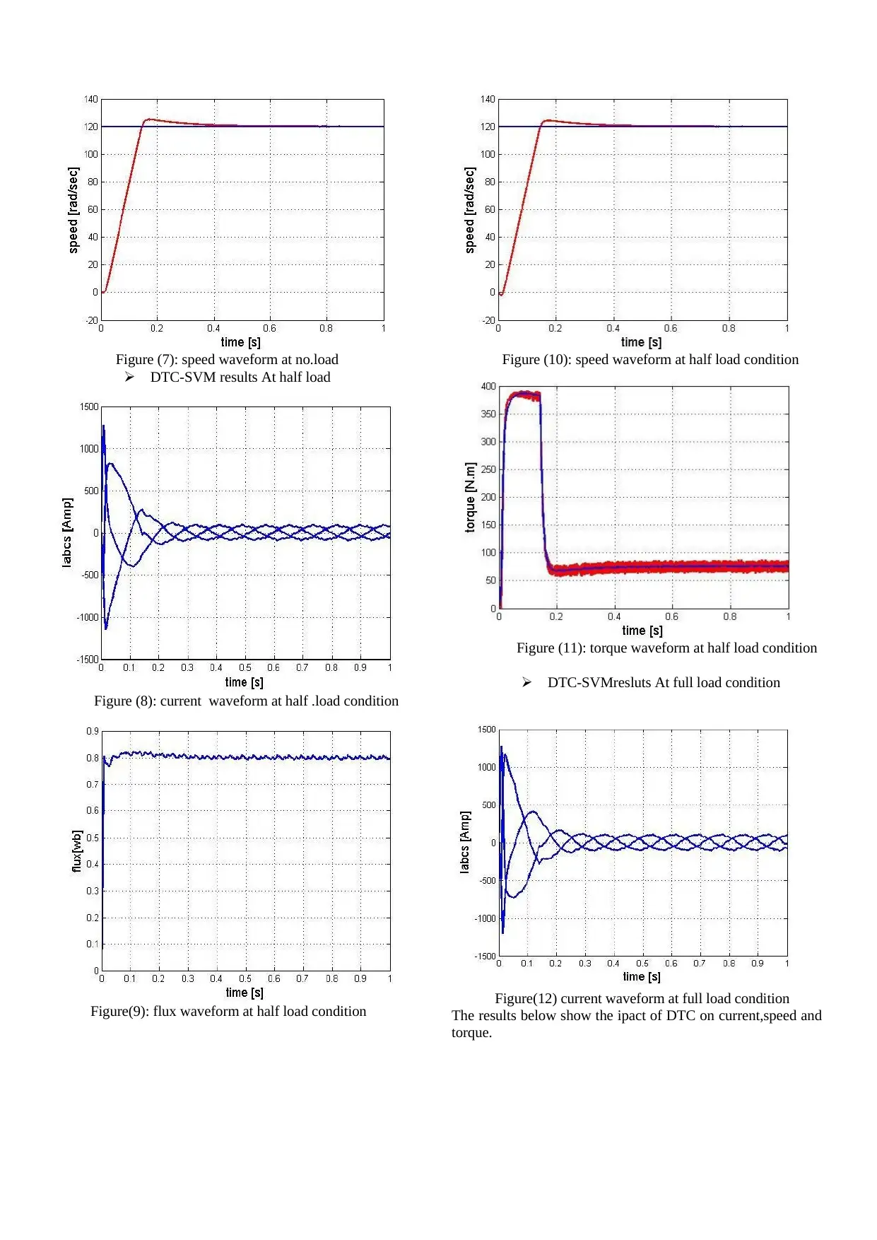
Figure (7): speed waveform at no.load
DTC-SVM results At half load
Figure (8): current waveform at half .load condition
Figure(9): flux waveform at half load condition
Figure (10): speed waveform at half load condition
Figure (11): torque waveform at half load condition
DTC-SVMresluts At full load condition
Figure(12) current waveform at full load condition
The results below show the ipact of DTC on current,speed and
torque.
Paraphrase This Document
Need a fresh take? Get an instant paraphrase of this document with our AI Paraphraser
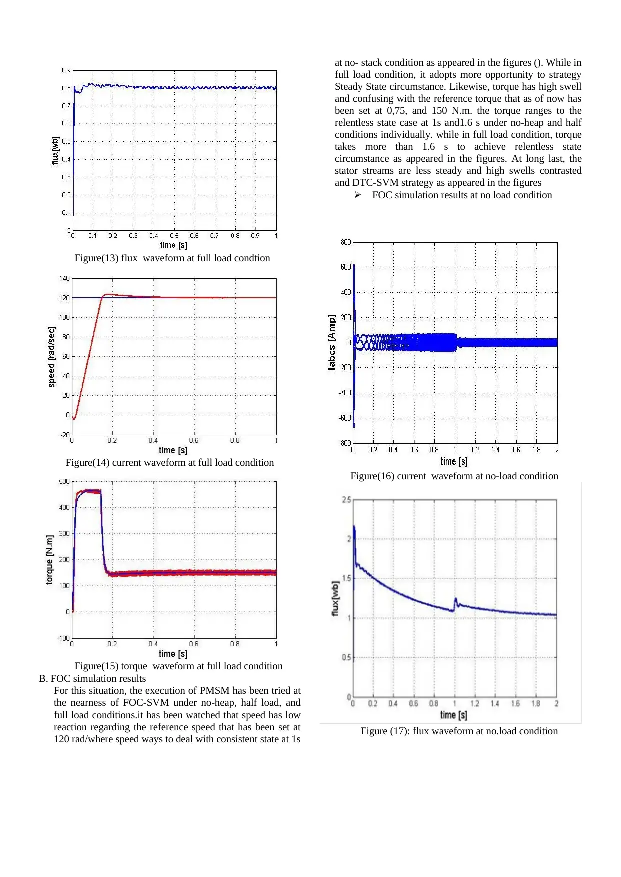
Figure(13) flux waveform at full load condtion
Figure(14) current waveform at full load condition
Figure(15) torque waveform at full load condition
B. FOC simulation results
For this situation, the execution of PMSM has been tried at
the nearness of FOC-SVM under no-heap, half load, and
full load conditions.it has been watched that speed has low
reaction regarding the reference speed that has been set at
120 rad/where speed ways to deal with consistent state at 1s
at no- stack condition as appeared in the figures (). While in
full load condition, it adopts more opportunity to strategy
Steady State circumstance. Likewise, torque has high swell
and confusing with the reference torque that as of now has
been set at 0,75, and 150 N.m. the torque ranges to the
relentless state case at 1s and1.6 s under no-heap and half
conditions individually. while in full load condition, torque
takes more than 1.6 s to achieve relentless state
circumstance as appeared in the figures. At long last, the
stator streams are less steady and high swells contrasted
and DTC-SVM strategy as appeared in the figures
FOC simulation results at no load condition
Figure(16) current waveform at no-load condition
Figure (17): flux waveform at no.load condition
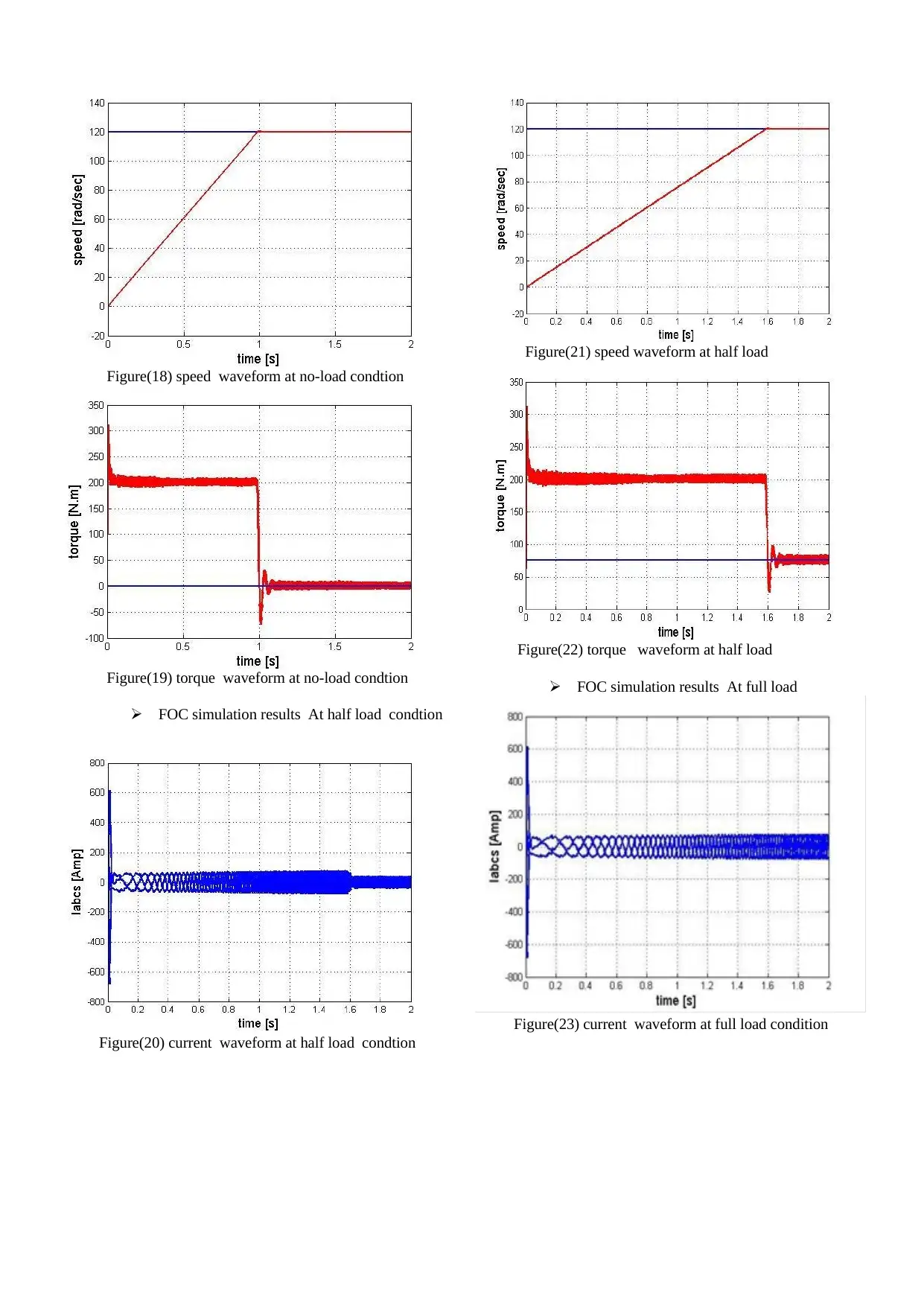
Figure(18) speed waveform at no-load condtion
Figure(19) torque waveform at no-load condtion
FOC simulation results At half load condtion
Figure(20) current waveform at half load condtion
Figure(21) speed waveform at half load
Figure(22) torque waveform at half load
FOC simulation results At full load
Figure(23) current waveform at full load condition
⊘ This is a preview!⊘
Do you want full access?
Subscribe today to unlock all pages.
Trusted by 1+ million students worldwide
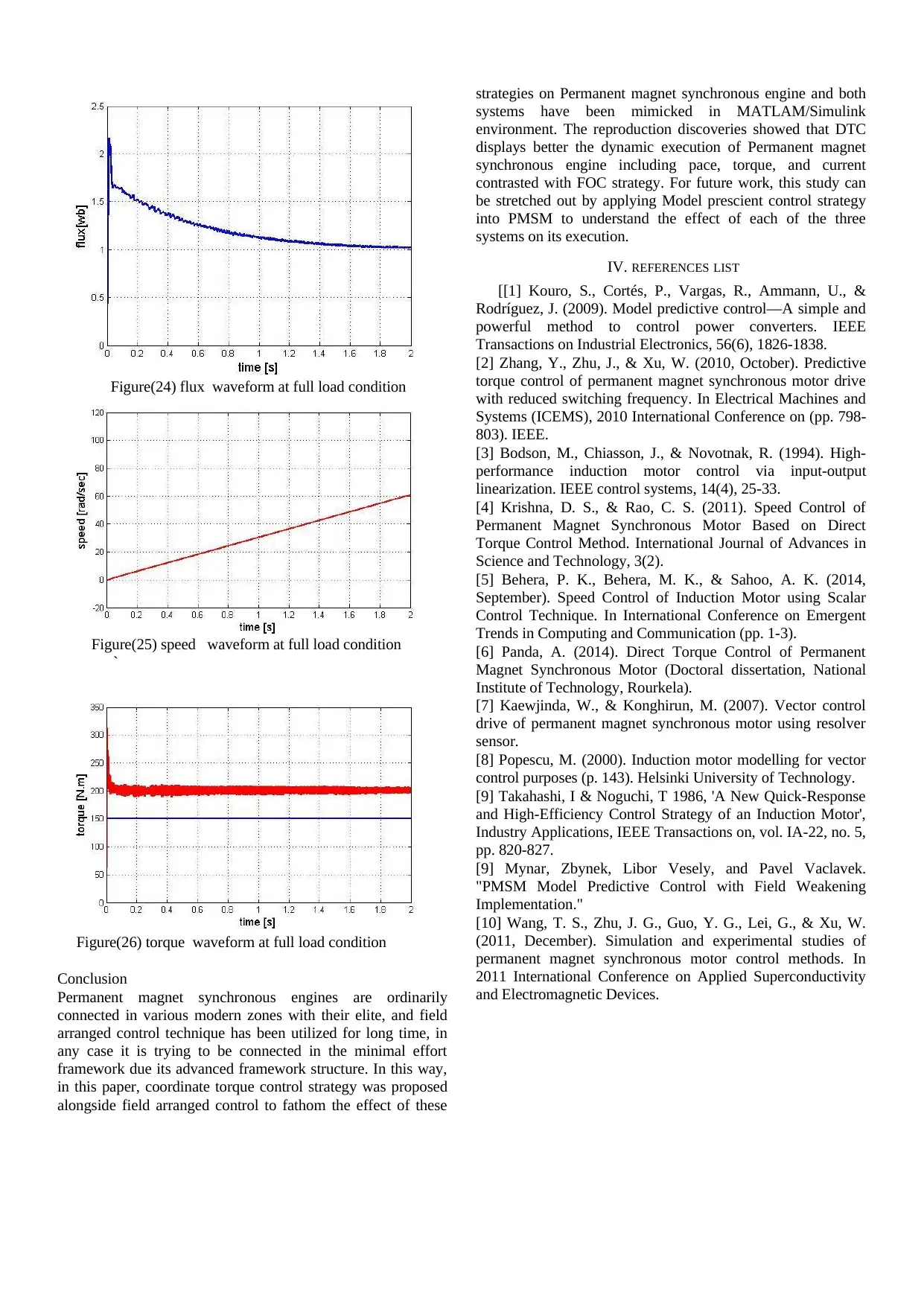
Figure(24) flux waveform at full load condition
Figure(25) speed waveform at full load condition
`
Figure(26) torque waveform at full load condition
Conclusion
Permanent magnet synchronous engines are ordinarily
connected in various modern zones with their elite, and field
arranged control technique has been utilized for long time, in
any case it is trying to be connected in the minimal effort
framework due its advanced framework structure. In this way,
in this paper, coordinate torque control strategy was proposed
alongside field arranged control to fathom the effect of these
strategies on Permanent magnet synchronous engine and both
systems have been mimicked in MATLAM/Simulink
environment. The reproduction discoveries showed that DTC
displays better the dynamic execution of Permanent magnet
synchronous engine including pace, torque, and current
contrasted with FOC strategy. For future work, this study can
be stretched out by applying Model prescient control strategy
into PMSM to understand the effect of each of the three
systems on its execution.
IV. REFERENCES LIST
[[1] Kouro, S., Cortés, P., Vargas, R., Ammann, U., &
Rodríguez, J. (2009). Model predictive control—A simple and
powerful method to control power converters. IEEE
Transactions on Industrial Electronics, 56(6), 1826-1838.
[2] Zhang, Y., Zhu, J., & Xu, W. (2010, October). Predictive
torque control of permanent magnet synchronous motor drive
with reduced switching frequency. In Electrical Machines and
Systems (ICEMS), 2010 International Conference on (pp. 798-
803). IEEE.
[3] Bodson, M., Chiasson, J., & Novotnak, R. (1994). High-
performance induction motor control via input-output
linearization. IEEE control systems, 14(4), 25-33.
[4] Krishna, D. S., & Rao, C. S. (2011). Speed Control of
Permanent Magnet Synchronous Motor Based on Direct
Torque Control Method. International Journal of Advances in
Science and Technology, 3(2).
[5] Behera, P. K., Behera, M. K., & Sahoo, A. K. (2014,
September). Speed Control of Induction Motor using Scalar
Control Technique. In International Conference on Emergent
Trends in Computing and Communication (pp. 1-3).
[6] Panda, A. (2014). Direct Torque Control of Permanent
Magnet Synchronous Motor (Doctoral dissertation, National
Institute of Technology, Rourkela).
[7] Kaewjinda, W., & Konghirun, M. (2007). Vector control
drive of permanent magnet synchronous motor using resolver
sensor.
[8] Popescu, M. (2000). Induction motor modelling for vector
control purposes (p. 143). Helsinki University of Technology.
[9] Takahashi, I & Noguchi, T 1986, 'A New Quick-Response
and High-Efficiency Control Strategy of an Induction Motor',
Industry Applications, IEEE Transactions on, vol. IA-22, no. 5,
pp. 820-827.
[9] Mynar, Zbynek, Libor Vesely, and Pavel Vaclavek.
"PMSM Model Predictive Control with Field Weakening
Implementation."
[10] Wang, T. S., Zhu, J. G., Guo, Y. G., Lei, G., & Xu, W.
(2011, December). Simulation and experimental studies of
permanent magnet synchronous motor control methods. In
2011 International Conference on Applied Superconductivity
and Electromagnetic Devices.
1 out of 7
Related Documents


Your All-in-One AI-Powered Toolkit for Academic Success.
+13062052269
info@desklib.com
Available 24*7 on WhatsApp / Email
![[object Object]](/_next/static/media/star-bottom.7253800d.svg)
Unlock your academic potential
Copyright © 2020–2026 A2Z Services. All Rights Reserved. Developed and managed by ZUCOL.