HNC Construction and Built Environment: Electrical Design Assignment 1
VerifiedAdded on 2022/12/14
|8
|827
|306
Homework Assignment
AI Summary
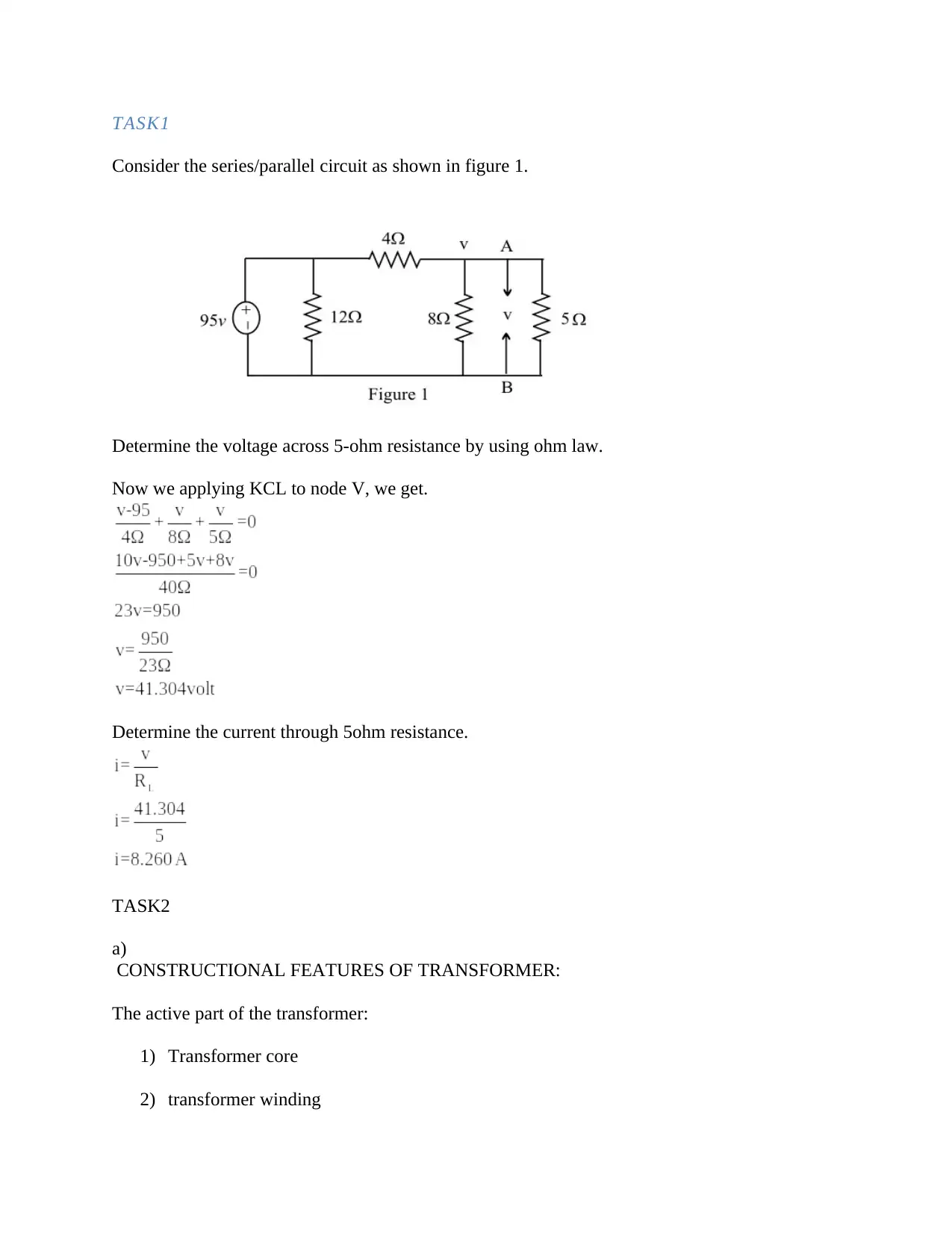
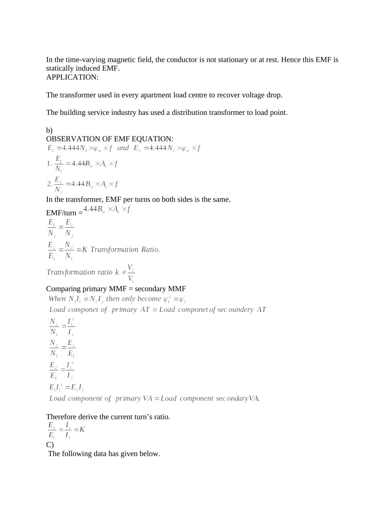
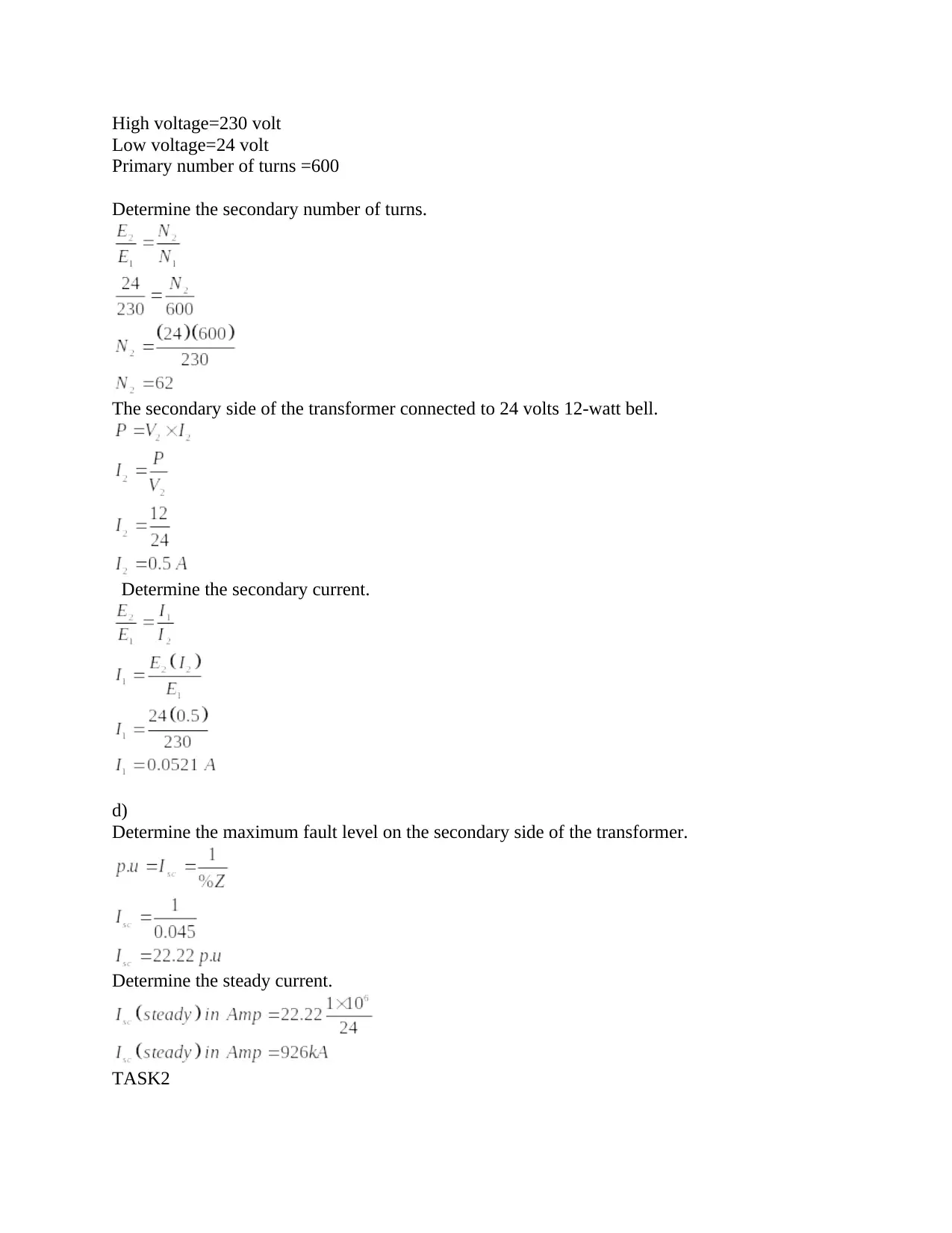
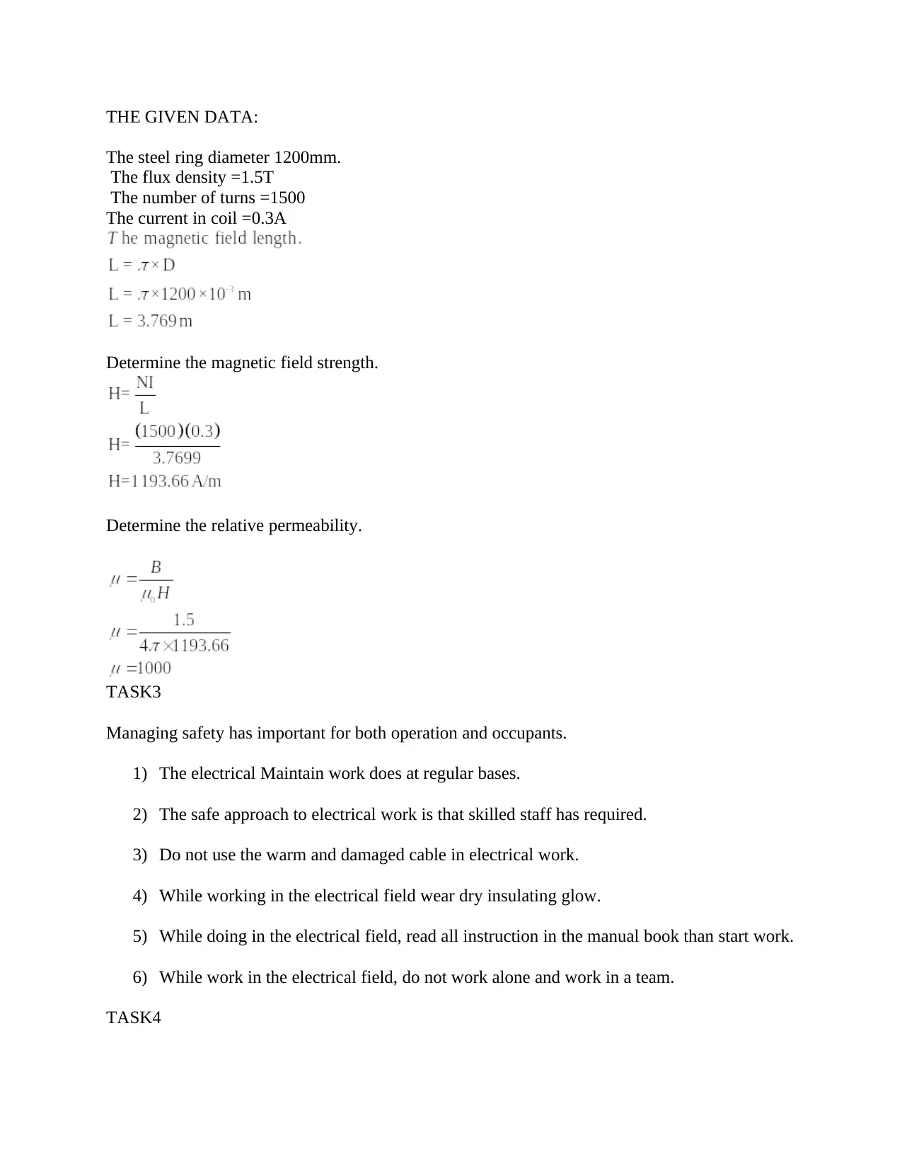
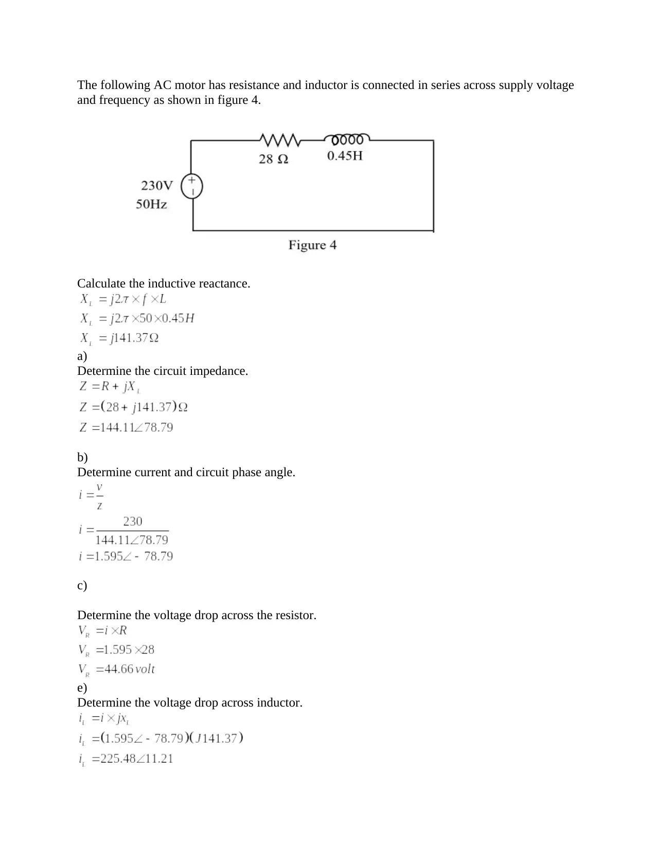
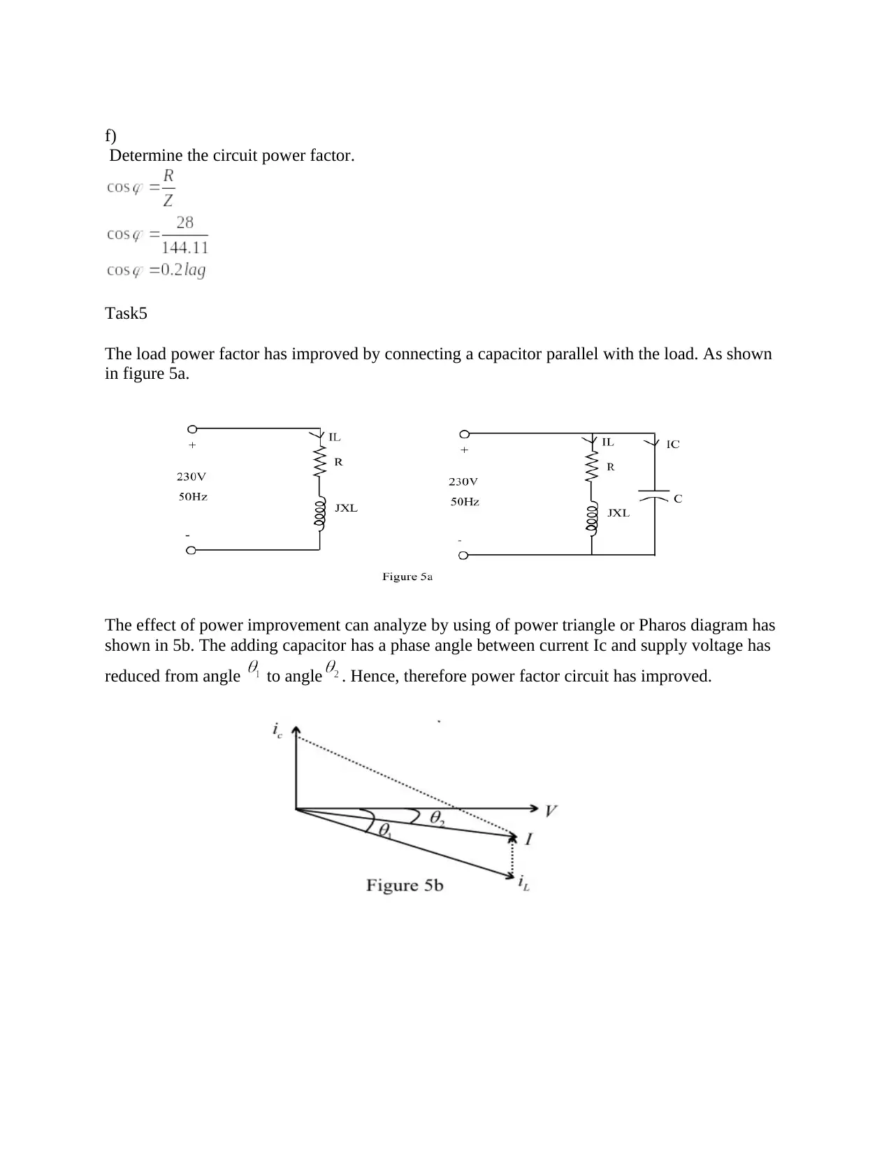
This assignment covers fundamental concepts in electrical engineering, including circuit analysis using Ohm's Law and Kirchhoff's Current Law (KCL). It explores the construction and operation of transformers, including core and winding materials, insulation, and the application of Lenz's and Faraday's laws. The assignment includes calculations related to transformer turns ratio, secondary current, and fault levels. Additionally, it delves into magnetic field strength and relative permeability calculations for a steel ring. The document also emphasizes safety protocols in electrical work. Finally, the assignment analyzes AC motor circuits, calculating inductive reactance, impedance, current, phase angle, voltage drops, and power factor, along with power factor correction using capacitors.

TASK1
Consider the series/parallel circuit as shown in figure 1.
Determine the voltage across 5-ohm resistance by using ohm law.
Now we applying KCL to node V, we get.
Determine the current through 5ohm resistance.
TASK2
a)
CONSTRUCTIONAL FEATURES OF TRANSFORMER:
The active part of the transformer:
1) Transformer core
2) transformer winding
Paraphrase This Document
Need a fresh take? Get an instant paraphrase of this document with our AI Paraphraser

Transformer core: the most of electrical machines, the magnetic circuit is made up of silicon
steel.
Transformer winding:
Transformer winding is made of either by Aluminium or copper.
Winding is not made up of single solid conductor because of stray current in a solid conductor
due to this stray current stray loss will be produced.
So we replace solid conductor with the stranded conductor.
Stay current cannot pass from one stand to another stranded conductor.
Advantage of stranded conductor:
1) To reduced stray load loss in the conductor due to stray current.
2) To reduced skin effect of the winding.
Lamination:
Insulation material lamination is required for electrical isolation.
Eddy current passes from one lamination to another if no insulation is provided.
Insulating material:
1) Oxide paint
2) China clay
3) Japan varnish
4) Thin impregnated paper
LENZ’S LAW:
The direction of statically induced EMF is such that the current due to this EMF will flow
through a conductor in such a direction which in turn produces some flux according to
electromagnet theory and this flux must oppose the change in main field flux which is cause for
the production of EMF as well as current.
FARADAY’S LAW
The main aim of Faraday's law is to generate EMF in the conductor.
Whenever there is relative space (or) time variation between the magnetic field and conductor
the EMF will induce in the conductor this faraday’s law.

In the time-varying magnetic field, the conductor is not stationary or at rest. Hence this EMF is
statically induced EMF.
APPLICATION:
The transformer used in every apartment load centre to recover voltage drop.
The building service industry has used a distribution transformer to load point.
b)
OBSERVATION OF EMF EQUATION:
In the transformer, EMF per turns on both sides is the same.
EMF/turn =
Comparing primary MMF = secondary MMF
Therefore derive the current turn’s ratio.
C)
The following data has given below.
⊘ This is a preview!⊘
Do you want full access?
Subscribe today to unlock all pages.

Trusted by 1+ million students worldwide

High voltage=230 volt
Low voltage=24 volt
Primary number of turns =600
Determine the secondary number of turns.
The secondary side of the transformer connected to 24 volts 12-watt bell.
Determine the secondary current.
d)
Determine the maximum fault level on the secondary side of the transformer.
Determine the steady current.
TASK2
Paraphrase This Document
Need a fresh take? Get an instant paraphrase of this document with our AI Paraphraser

THE GIVEN DATA:
The steel ring diameter 1200mm.
The flux density =1.5T
The number of turns =1500
The current in coil =0.3A
Determine the magnetic field strength.
Determine the relative permeability.
TASK3
Managing safety has important for both operation and occupants.
1) The electrical Maintain work does at regular bases.
2) The safe approach to electrical work is that skilled staff has required.
3) Do not use the warm and damaged cable in electrical work.
4) While working in the electrical field wear dry insulating glow.
5) While doing in the electrical field, read all instruction in the manual book than start work.
6) While work in the electrical field, do not work alone and work in a team.
TASK4

The following AC motor has resistance and inductor is connected in series across supply voltage
and frequency as shown in figure 4.
Calculate the inductive reactance.
a)
Determine the circuit impedance.
b)
Determine current and circuit phase angle.
c)
Determine the voltage drop across the resistor.
e)
Determine the voltage drop across inductor.
and frequency as shown in figure 4.
Calculate the inductive reactance.
a)
Determine the circuit impedance.
b)
Determine current and circuit phase angle.
c)
Determine the voltage drop across the resistor.
e)
Determine the voltage drop across inductor.
⊘ This is a preview!⊘
Do you want full access?
Subscribe today to unlock all pages.

Trusted by 1+ million students worldwide

f)
Determine the circuit power factor.
Task5
The load power factor has improved by connecting a capacitor parallel with the load. As shown
in figure 5a.
The effect of power improvement can analyze by using of power triangle or Pharos diagram has
shown in 5b. The adding capacitor has a phase angle between current Ic and supply voltage has
reduced from angle to angle . Hence, therefore power factor circuit has improved.
Paraphrase This Document
Need a fresh take? Get an instant paraphrase of this document with our AI Paraphraser

The power factor improved from to without affecting the real power
therefore new reactive power .
The reactive power KVA has reduced due to shunt capacitance. The mathematical equation can
see below.
The capacitance values are finding by using this equation.
Hence, therefore we observe that KVA has reduced due to capacitance effect.
therefore new reactive power .
The reactive power KVA has reduced due to shunt capacitance. The mathematical equation can
see below.
The capacitance values are finding by using this equation.
Hence, therefore we observe that KVA has reduced due to capacitance effect.
1 out of 8
Related Documents

Your All-in-One AI-Powered Toolkit for Academic Success.
+13062052269
info@desklib.com
Available 24*7 on WhatsApp / Email
Unlock your academic potential
Copyright © 2020–2025 A2Z Services. All Rights Reserved. Developed and managed by ZUCOL.