Principles of Structural Design: Beam Analysis and Deflection Study

Verified

Added on  2022/11/15

|19
|4524
|345
Report
AI Summary
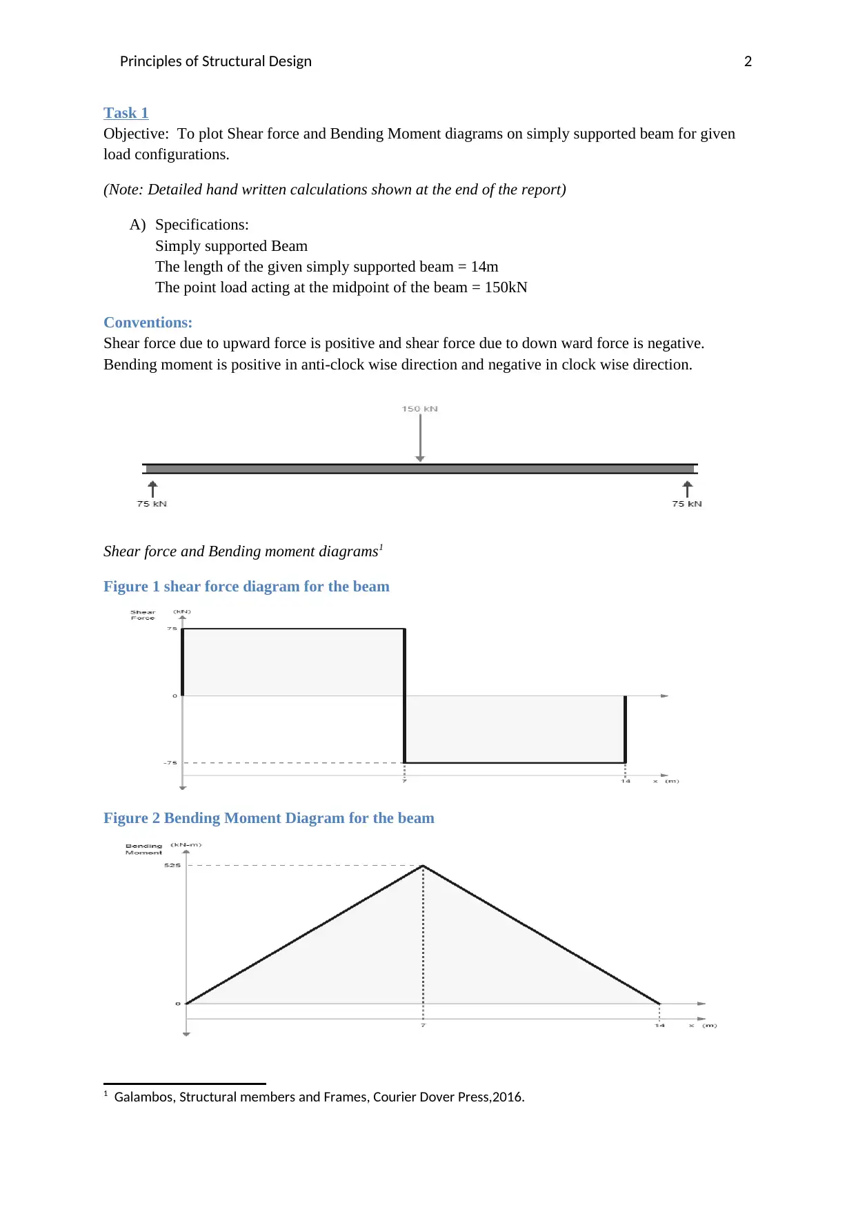
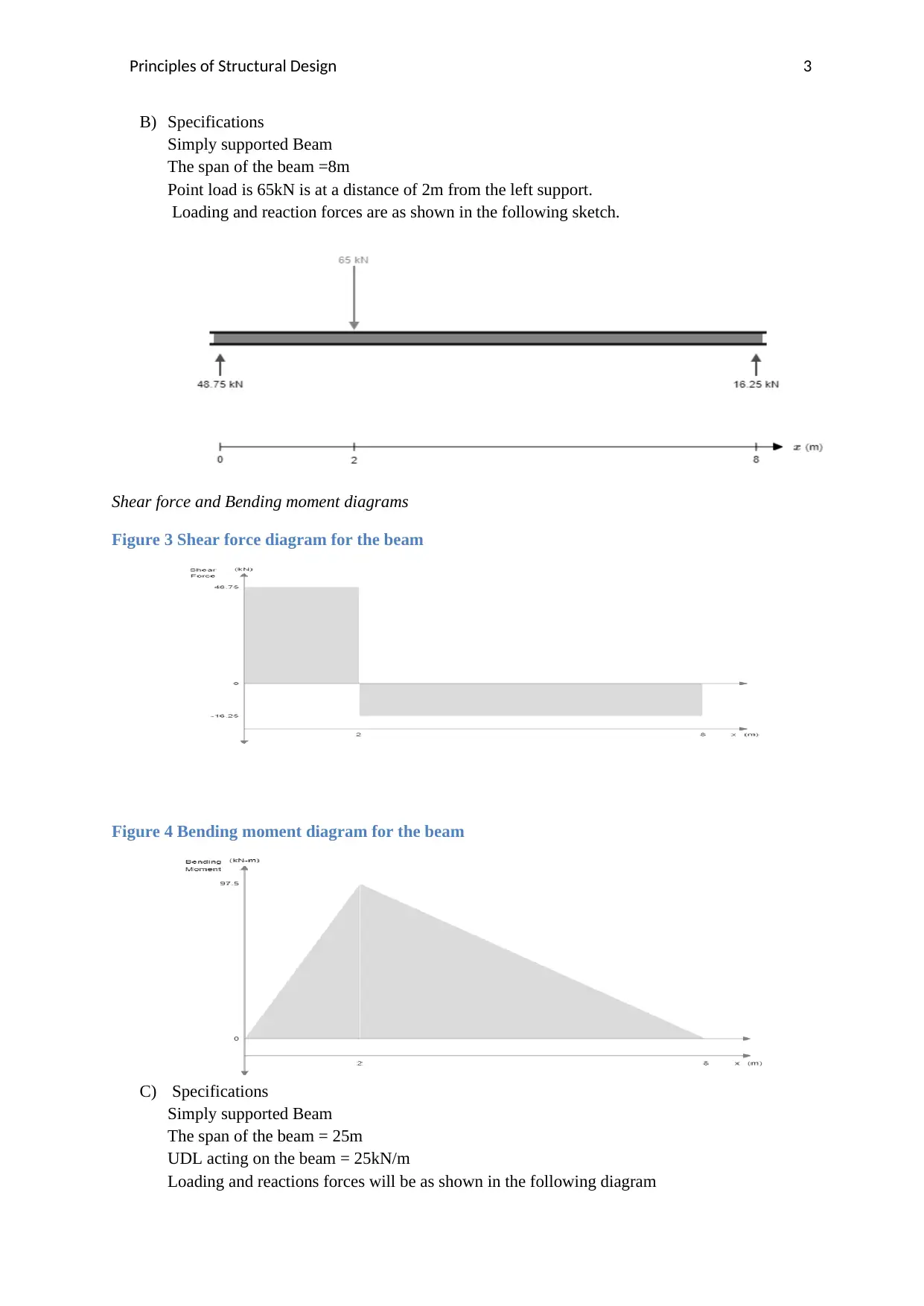
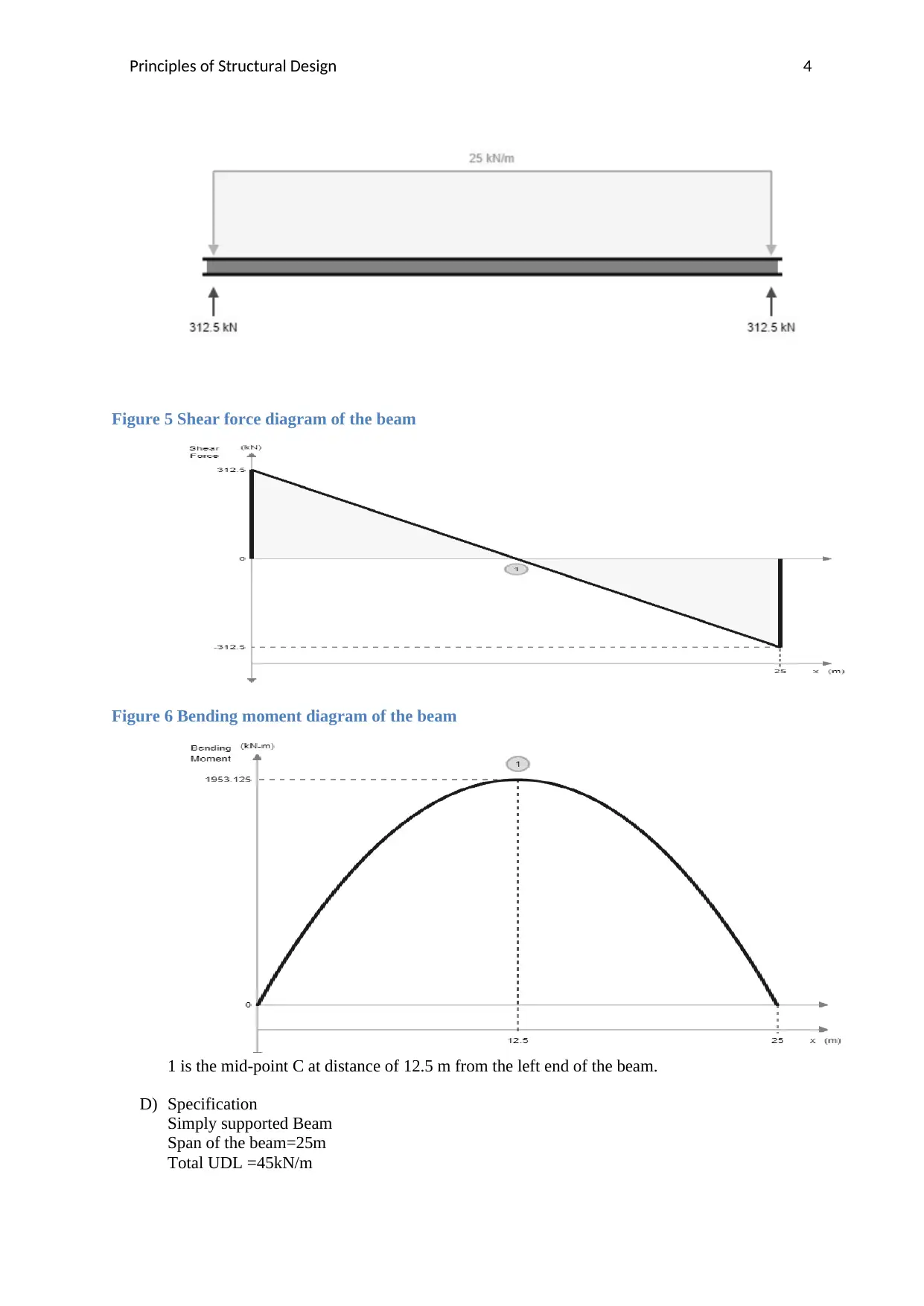
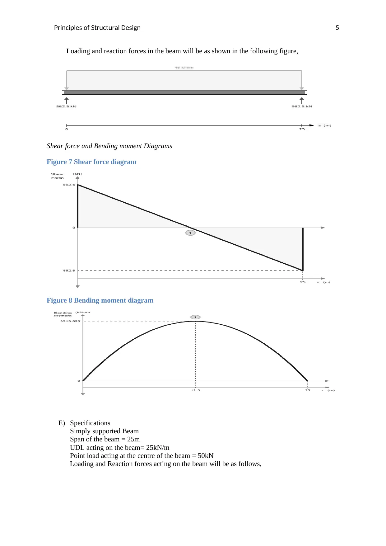
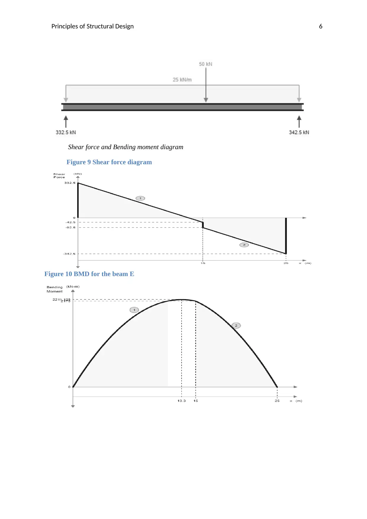
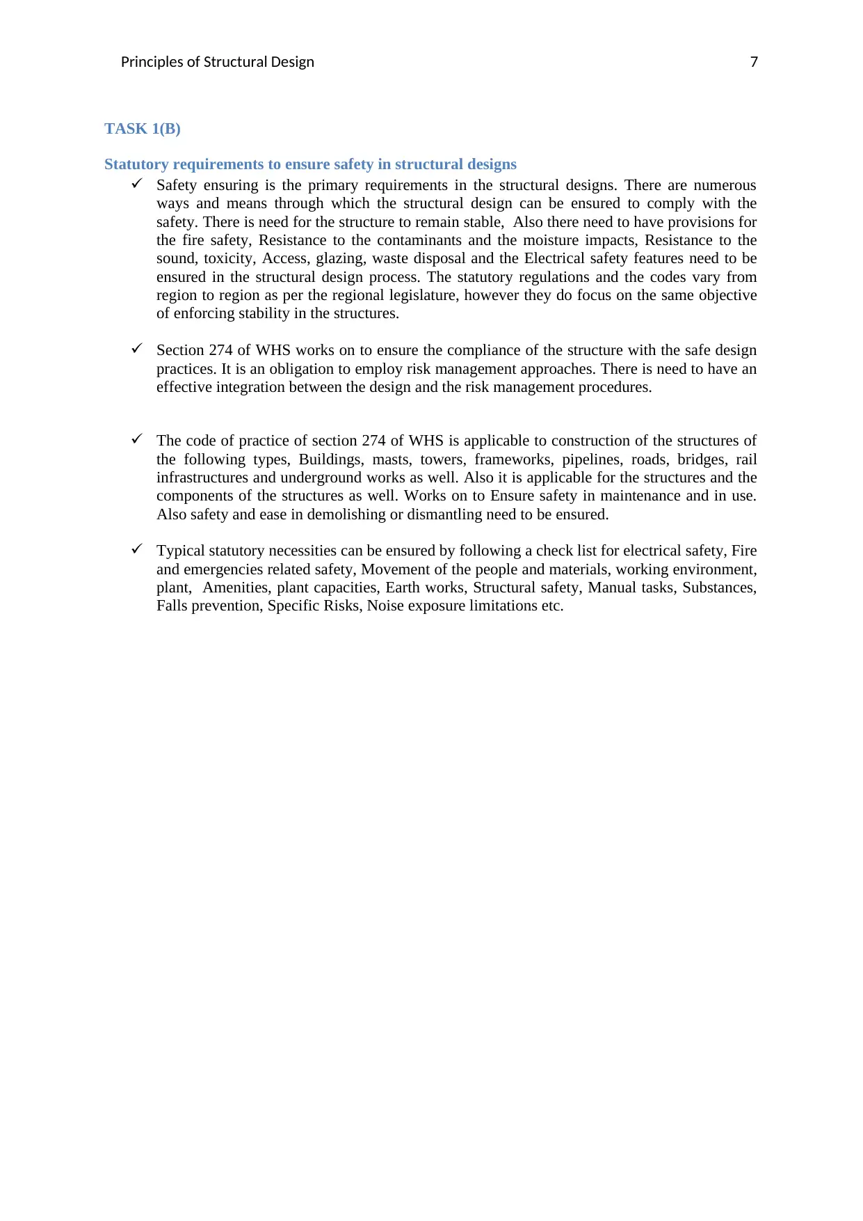
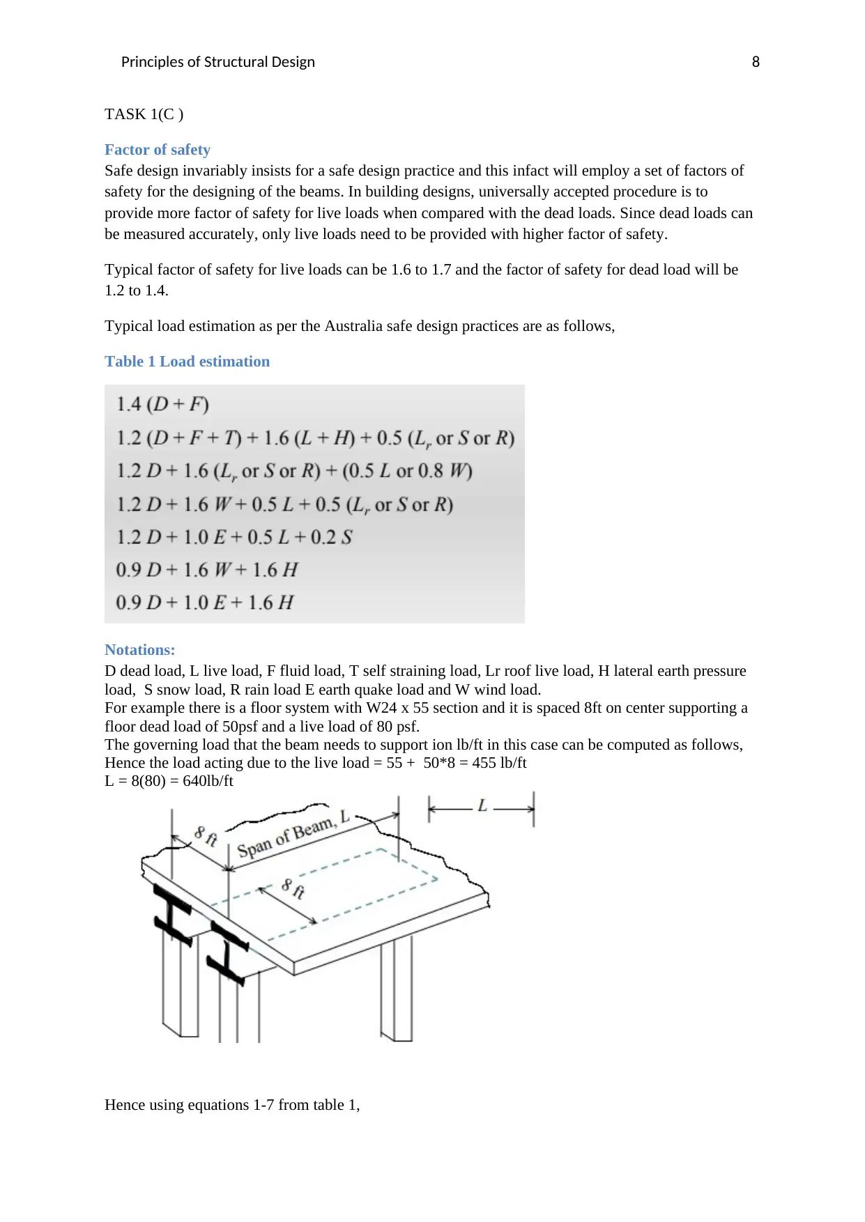
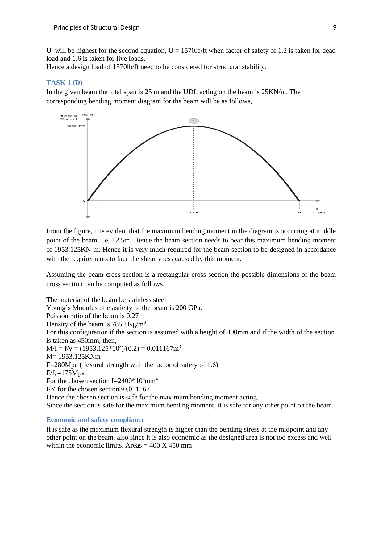
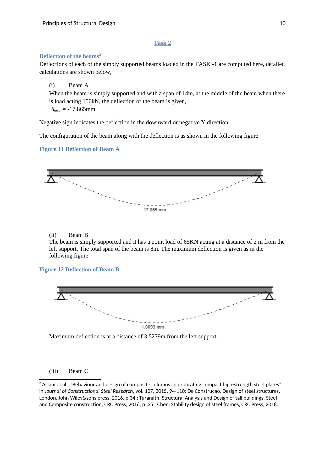
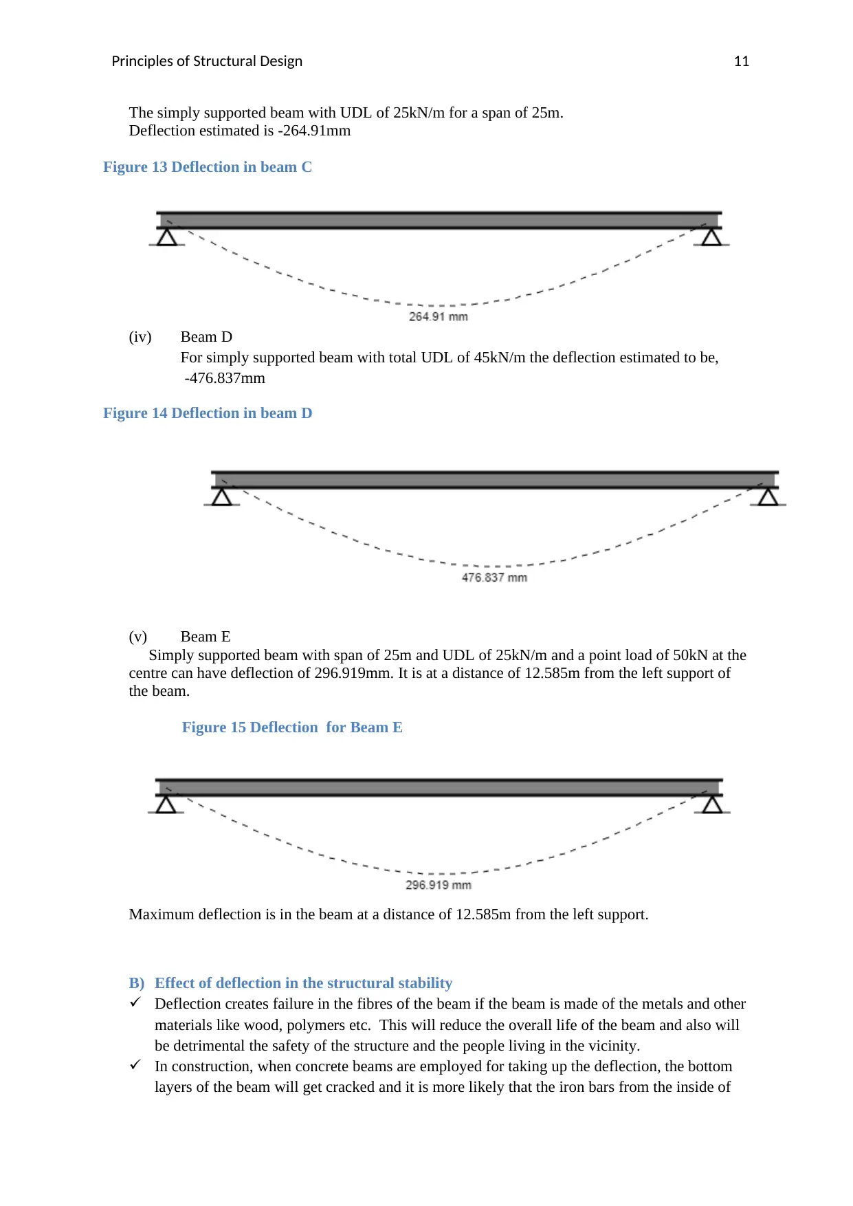
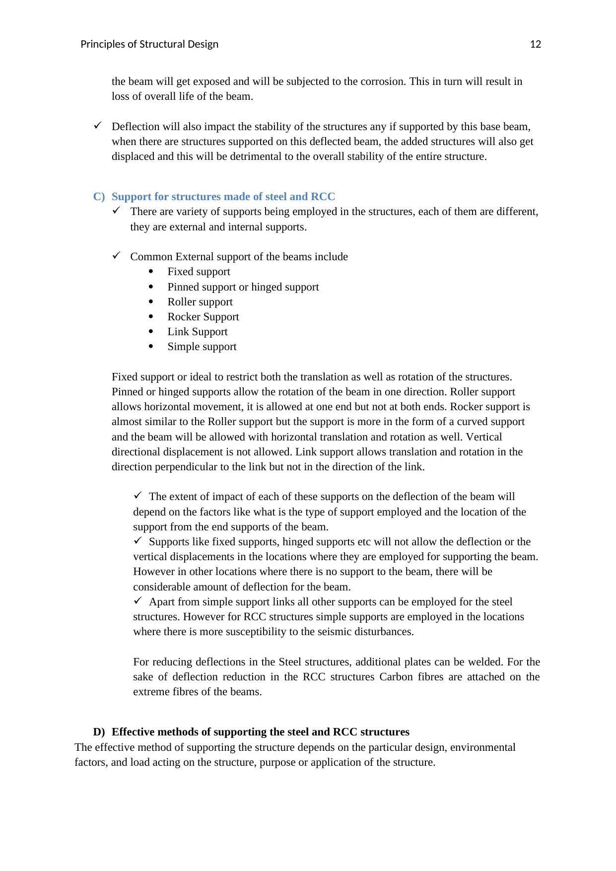
This report delves into the principles of structural design, focusing on the analysis of simply supported beams under various load configurations. It presents detailed calculations and diagrams for shear force and bending moment, illustrating the behavior of beams subjected to point loads and uniformly distributed loads (UDL). The report also addresses statutory requirements for ensuring safety in structural designs, emphasizing the importance of risk management and compliance with relevant codes and regulations. Furthermore, it explores the concept of the factor of safety, detailing load estimation methods and providing examples to determine design loads. The analysis extends to deflection calculations for each beam configuration, examining the impact of deflection on structural stability and discussing different types of beam supports and their influence on deflection. Finally, the report includes a case study on a beam under UDL, calculating bending moment and designing a safe and economic cross-section. It concludes by discussing the effects of deflection on structural stability and the role of various support types in managing deflection in steel and reinforced concrete structures.
Document Page
Principles of Structural Design
Running Head: Principles of Structural Design
Title: Principles of Structural Design
Student Name and Id:
Course Name and Id:
University:
Date of Submission: 17/7/2019
Authors Note
The current report is submitted as part of the requirements to complete the course work.
tabler-icon-diamond-filled.svg

Paraphrase This Document

Need a fresh take? Get an instant paraphrase of this document with our AI Paraphraser
Document Page
Principles of Structural Design 2
Task 1
Objective: To plot Shear force and Bending Moment diagrams on simply supported beam for given
load configurations.
(Note: Detailed hand written calculations shown at the end of the report)
A) Specifications:
Simply supported Beam
The length of the given simply supported beam = 14m
The point load acting at the midpoint of the beam = 150kN
Conventions:
Shear force due to upward force is positive and shear force due to down ward force is negative.
Bending moment is positive in anti-clock wise direction and negative in clock wise direction.
Shear force and Bending moment diagrams1
Figure 1 shear force diagram for the beam
Figure 2 Bending Moment Diagram for the beam
1 Galambos, Structural members and Frames, Courier Dover Press,2016.
Document Page
Principles of Structural Design 3
B) Specifications
Simply supported Beam
The span of the beam =8m
Point load is 65kN is at a distance of 2m from the left support.
Loading and reaction forces are as shown in the following sketch.
Shear force and Bending moment diagrams
Figure 3 Shear force diagram for the beam
Figure 4 Bending moment diagram for the beam
C) Specifications
Simply supported Beam
The span of the beam = 25m
UDL acting on the beam = 25kN/m
Loading and reactions forces will be as shown in the following diagram
Document Page
Principles of Structural Design 4
Figure 5 Shear force diagram of the beam
Figure 6 Bending moment diagram of the beam
1 is the mid-point C at distance of 12.5 m from the left end of the beam.
D) Specification
Simply supported Beam
Span of the beam=25m
Total UDL =45kN/m
tabler-icon-diamond-filled.svg

Paraphrase This Document

Need a fresh take? Get an instant paraphrase of this document with our AI Paraphraser
Document Page
Principles of Structural Design 5
Loading and reaction forces in the beam will be as shown in the following figure,
Shear force and Bending moment Diagrams
Figure 7 Shear force diagram
Figure 8 Bending moment diagram
E) Specifications
Simply supported Beam
Span of the beam = 25m
UDL acting on the beam= 25kN/m
Point load acting at the centre of the beam = 50kN
Loading and Reaction forces acting on the beam will be as follows,
Document Page
Principles of Structural Design 6
Shear force and Bending moment diagram
Figure 9 Shear force diagram
Figure 10 BMD for the beam E
Document Page
Principles of Structural Design 7
TASK 1(B)
Statutory requirements to ensure safety in structural designs
Safety ensuring is the primary requirements in the structural designs. There are numerous
ways and means through which the structural design can be ensured to comply with the
safety. There is need for the structure to remain stable, Also there need to have provisions for
the fire safety, Resistance to the contaminants and the moisture impacts, Resistance to the
sound, toxicity, Access, glazing, waste disposal and the Electrical safety features need to be
ensured in the structural design process. The statutory regulations and the codes vary from
region to region as per the regional legislature, however they do focus on the same objective
of enforcing stability in the structures.
Section 274 of WHS works on to ensure the compliance of the structure with the safe design
practices. It is an obligation to employ risk management approaches. There is need to have an
effective integration between the design and the risk management procedures.
The code of practice of section 274 of WHS is applicable to construction of the structures of
the following types, Buildings, masts, towers, frameworks, pipelines, roads, bridges, rail
infrastructures and underground works as well. Also it is applicable for the structures and the
components of the structures as well. Works on to Ensure safety in maintenance and in use.
Also safety and ease in demolishing or dismantling need to be ensured.
Typical statutory necessities can be ensured by following a check list for electrical safety, Fire
and emergencies related safety, Movement of the people and materials, working environment,
plant, Amenities, plant capacities, Earth works, Structural safety, Manual tasks, Substances,
Falls prevention, Specific Risks, Noise exposure limitations etc.
tabler-icon-diamond-filled.svg

Paraphrase This Document

Need a fresh take? Get an instant paraphrase of this document with our AI Paraphraser
Document Page
Principles of Structural Design 8
TASK 1(C )
Factor of safety
Safe design invariably insists for a safe design practice and this infact will employ a set of factors of
safety for the designing of the beams. In building designs, universally accepted procedure is to
provide more factor of safety for live loads when compared with the dead loads. Since dead loads can
be measured accurately, only live loads need to be provided with higher factor of safety.
Typical factor of safety for live loads can be 1.6 to 1.7 and the factor of safety for dead load will be
1.2 to 1.4.
Typical load estimation as per the Australia safe design practices are as follows,
Table 1 Load estimation
Notations:
D dead load, L live load, F fluid load, T self straining load, Lr roof live load, H lateral earth pressure
load, S snow load, R rain load E earth quake load and W wind load.
For example there is a floor system with W24 x 55 section and it is spaced 8ft on center supporting a
floor dead load of 50psf and a live load of 80 psf.
The governing load that the beam needs to support ion lb/ft in this case can be computed as follows,
Hence the load acting due to the live load = 55 + 50*8 = 455 lb/ft
L = 8(80) = 640lb/ft
Hence using equations 1-7 from table 1,
Document Page
Principles of Structural Design 9
U will be highest for the second equation, U = 1570lb/ft when factor of safety of 1.2 is taken for dead
load and 1.6 is taken for live loads.
Hence a design load of 1570lb/ft need to be considered for structural stability.
TASK 1 (D)
In the given beam the total span is 25 m and the UDL acting on the beam is 25KN/m. The
corresponding bending moment diagram for the beam will be as follows,
From the figure, it is evident that the maximum bending moment in the diagram is occurring at middle
point of the beam, i.e, 12.5m. Hence the beam section needs to bear this maximum bending moment
of 1953.125KN-m. Hence it is very much required for the beam section to be designed in accordance
with the requirements to face the shear stress caused by this moment.
Assuming the beam cross section is a rectangular cross section the possible dimensions of the beam
cross section can be computed as follows,
The material of the beam be stainless steel
Young’s Modulus of elasticity of the beam is 200 GPa.
Poisson ratio of the beam is 0.27
Density of the beam is 7850 Kg/m3
For this configuration if the section is assumed with a height of 400mm and if the width of the section
is taken as 450mm, then,
M/I = f/y = (1953.125*103)/(0.2) = 0.011167m3
M= 1953.125KNm
F=280Mpa (flexural strength with the factor of safety of 1.6)
F/fs =175Mpa
For the chosen section I=2400*106mm4
I/Y for the chosen section>0.011167
Hence the chosen section is safe for the maximum bending moment acting.
Since the section is safe for the maximum bending moment, it is safe for any other point on the beam.
Economic and safety compliance
It is safe as the maximum flexural strength is higher than the bending stress at the midpoint and any
other point on the beam, also since it is also economic as the designed area is not too excess and well
within the economic limits. Areas = 400 X 450 mm
Document Page
Principles of Structural Design 10
Task 2
Deflection of the beams2
Deflections of each of the simply supported beams loaded in the TASK -1 are computed here, detailed
calculations are shown below,
(i) Beam A
When the beam is simply supported and with a span of 14m, at the middle of the beam when there
is load acting 150kN, the deflection of the beam is given,
δmax = -17.865mm
Negative sign indicates the deflection in the downward or negative Y direction
The configuration of the beam along with the deflection is as shown in the following figure
Figure 11 Deflection of Beam A
(ii) Beam B
The beam is simply supported and it has a point load of 65KN acting at a distance of 2 m from the
left support. The total span of the beam is 8m. The maximum deflection is given as in the
following figure
Figure 12 Deflection of Beam B
Maximum deflection is at a distance of 3.5279m from the left support.
(iii) Beam C
2 Aslani et al., "Behaviour and design of composite columns incorporating compact high-strength steel plates",
in Journal of Constructional Steel Research, vol. 107, 2015, 94-110; De Construcao, Design of steel structures,
London, John Wiley&sons press, 2016, p.34.; Taranath, Structural Analysis and Design of tall buildings, Steel
and Composite construction, CRC Press, 2016, p. 35.; Chen, Stability design of steel frames, CRC Press, 2018.
tabler-icon-diamond-filled.svg

Paraphrase This Document

Need a fresh take? Get an instant paraphrase of this document with our AI Paraphraser
Document Page
Principles of Structural Design 11
The simply supported beam with UDL of 25kN/m for a span of 25m.
Deflection estimated is -264.91mm
Figure 13 Deflection in beam C
(iv) Beam D
For simply supported beam with total UDL of 45kN/m the deflection estimated to be,
-476.837mm
Figure 14 Deflection in beam D
(v) Beam E
Simply supported beam with span of 25m and UDL of 25kN/m and a point load of 50kN at the
centre can have deflection of 296.919mm. It is at a distance of 12.585m from the left support of
the beam.
Figure 15 Deflection for Beam E
Maximum deflection is in the beam at a distance of 12.585m from the left support.
B) Effect of deflection in the structural stability
Deflection creates failure in the fibres of the beam if the beam is made of the metals and other
materials like wood, polymers etc. This will reduce the overall life of the beam and also will
be detrimental the safety of the structure and the people living in the vicinity.
In construction, when concrete beams are employed for taking up the deflection, the bottom
layers of the beam will get cracked and it is more likely that the iron bars from the inside of
Document Page
Principles of Structural Design 12
the beam will get exposed and will be subjected to the corrosion. This in turn will result in
loss of overall life of the beam.
Deflection will also impact the stability of the structures any if supported by this base beam,
when there are structures supported on this deflected beam, the added structures will also get
displaced and this will be detrimental to the overall stability of the entire structure.
C) Support for structures made of steel and RCC
There are variety of supports being employed in the structures, each of them are different,
they are external and internal supports.
Common External support of the beams include
Fixed support
Pinned support or hinged support
Roller support
Rocker Support
Link Support
Simple support
Fixed support or ideal to restrict both the translation as well as rotation of the structures.
Pinned or hinged supports allow the rotation of the beam in one direction. Roller support
allows horizontal movement, it is allowed at one end but not at both ends. Rocker support is
almost similar to the Roller support but the support is more in the form of a curved support
and the beam will be allowed with horizontal translation and rotation as well. Vertical
directional displacement is not allowed. Link support allows translation and rotation in the
direction perpendicular to the link but not in the direction of the link.
The extent of impact of each of these supports on the deflection of the beam will
depend on the factors like what is the type of support employed and the location of the
support from the end supports of the beam.
Supports like fixed supports, hinged supports etc will not allow the deflection or the
vertical displacements in the locations where they are employed for supporting the beam.
However in other locations where there is no support to the beam, there will be
considerable amount of deflection for the beam.
Apart from simple support links all other supports can be employed for the steel
structures. However for RCC structures simple supports are employed in the locations
where there is more susceptibility to the seismic disturbances.
For reducing deflections in the Steel structures, additional plates can be welded. For the
sake of deflection reduction in the RCC structures Carbon fibres are attached on the
extreme fibres of the beams.
D) Effective methods of supporting the steel and RCC structures
The effective method of supporting the structure depends on the particular design, environmental
factors, and load acting on the structure, purpose or application of the structure.
chevron_up_icon
1 out of 19
circle_padding
hide_on_mobile
zoom_out_icon
[object Object]