Simple Online Shopping System Design
VerifiedAdded on 2020/05/16
|19
|3440
|417
AI Summary
This assignment describes the design of a basic online shopping system. It outlines user functionalities like searching products, adding to cart, checking out, and viewing project descriptions. The document includes use case diagrams, activity diagrams, sequence/interaction diagrams, and an Entity Relationship Diagram (ERD) to illustrate the system's architecture and data flow. A conclusion summarizes the project's simplicity and user-friendliness, emphasizing its accessibility for a wide range of customers.
Contribute Materials
Your contribution can guide someone’s learning journey. Share your
documents today.
1
Project Name: Online Shopping System
Laboratory Tasks
Software Requirements Specification
Project Name: Online Shopping System
Group Members
Project Name: Online Shopping System
Laboratory Tasks
Software Requirements Specification
Project Name: Online Shopping System
Group Members
Secure Best Marks with AI Grader
Need help grading? Try our AI Grader for instant feedback on your assignments.
2
Contents
Project Name: Online Shopping System....................................................................................1
Lab 1 Questions..........................................................................................................................3
Relational Database....................................................................................................................4
1 Name of Project.......................................................................................................................4
1.2 Overview..............................................................................................................................5
1.2.1 Purpose..........................................................................................................................5
1.2.2 Scope.............................................................................................................................5
1.3 Objective..............................................................................................................................5
1.4 Support.................................................................................................................................5
1.5 Stakeholders.........................................................................................................................5
Users.......................................................................................................................................5
1.6 Context of the System......................................................................................................5
1.7 Criteria for Acceptance....................................................................................................5
2 General Description................................................................................................................6
2.1 Functions..........................................................................................................................6
2.2 Characteristics of the user....................................................................................................6
2.3 Assumptions.....................................................................................................................7
2.3 Outlook of the products........................................................................................................7
2.4 User Base.............................................................................................................................7
2.5 Design Constraints...............................................................................................................7
2.6 Project Feasibility.............................................................................................................7
3 Requirements...........................................................................................................................7
3.1 Functional requirements.......................................................................................................7
3.2 Non-functional requirements...............................................................................................8
3.3 Automatically Generated Value Rules.................................................................................8
3.4 Interface Requirements........................................................................................................9
3.4.1 User interface................................................................................................................9
3.4.2 Hardware Interface........................................................................................................9
3.4.3 Software Interface.........................................................................................................9
3.5 Database Requirements........................................................................................................9
3.6 Software requirements.........................................................................................................9
3.7 Hardware requirements........................................................................................................9
3.8 Communication Protocols..................................................................................................10
3
3.9Extra Quality Requirements............................................................................................10
3.10 Training Requirements.................................................................................................10
3.11 Software Engineering Process Model..........................................................................10
Use-Case Diagram...................................................................................................................10
Use Case 1 – Administrator Login.......................................................................................10
Use Case 2 – User Login......................................................................................................11
Entity- Relationship Diagram..................................................................................................11
Context Analysis Diagram.......................................................................................................11
Data Flow Diagram..................................................................................................................11
Class Diagram..........................................................................................................................11
Appendix 1 - Class Diagram................................................................................................11
Appendix 2 USE-CASE DIAGRAM.......................................................................................12
Appendix 3 Entity- Relationship Diagram...............................................................................13
Appendix 4 Context Analysis Diagram...................................................................................13
Appendix 5 Level DFD for administrator................................................................................14
Appendix 6 Level DFD of Customers.....................................................................................15
Appendix 7 Activity diagram...................................................................................................16
Appendix 8 Activity Diagram 2...............................................................................................16
Appendix 9 Sequence/interaction diagram..............................................................................17
5 Conclusion.............................................................................................................................18
6 References.............................................................................................................................18
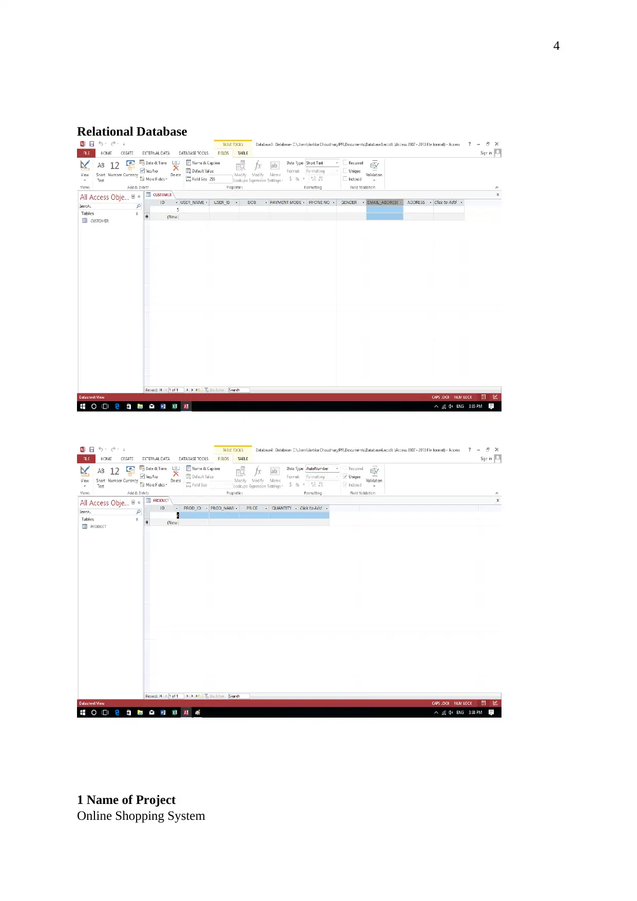
Lab 1 Questions
Table Name Attributes
Product 4 fields
Customers 9 fields
4
Relational Database
1 Name of Project
Online Shopping System
Relational Database
1 Name of Project
Online Shopping System
Secure Best Marks with AI Grader
Need help grading? Try our AI Grader for instant feedback on your assignments.
5
1.2Overview
For this particular lab assignment, we decided to choose an Online Shopping System. The
system is expected to be designed with web development tools like HTML, XML and a
relational database.
1.2.1 Purpose
The purpose of this system is to design an online shopping system application so that the
customers can browse through the shop and make their purchase. The system administrator
who is under the administration measure will be approving as well as rejecting the requests
for shops. He willalso be able to establish a list of shop category.For the data storage of the
entire system a relational database is developed i.e. an access database. [1].
1.2.2 Scope
With the help of this system the customer’s will be able to manage their cart over the internet
to remove or add any product.
1.3Objective
The main objective of this documentation is to analyze the requirements of the project. This
document is designed in a way that it explains all the functional and the non-functional
requirements of the system[2]. This system is expected to provide a feasible and user-friendly
environment for maintaining the cart of the customers and for purchasing the products.
The hardware and the software requirements are also mentioned and the whole system is
described with the help of diagrams like UML and ER diagrams.
1.4Support
A customer support service is also a part of the design of the system and hence after the
testing part of the system, the customers will be provided with any sort of support.
1.5Stakeholders
Users
This system’s end users the administrator and the customers as the customers will be adding
and removing the products from their cart. The administrator will accept and reject the
requests of the customers and will manage the list of shops.
1.6Context of the System
The online shopping system will be installed on the store’s website of any particular shop.
1.7Criteria for Acceptance
After the completion of the testing part, it was observed that the core functionalities of the
software are intact and the system was feasible. The system was running smooth and no
errors were observed. The system was also user-friendly and the customers needed no extra
skills to use the system. The acceptance criteria is defined when the user and system
6
acceptance testing gets complete. There should not be any problem which makes the
functions stop or a problem which may severely affect the functionality of the system. The
problem should not have any sort of effect on the business operations and any type of error in
the documentation should have no effect on the customer’s operations. If no such problem
exists then only the system will be accepted for a long term.
2 General Description
2.1 Functions
This online shopping system will contain many functions which will help in reducing the
time of the customers in going to the store and buying products. The system is designed in a
way that it is user friendly and hence can easily be accessible by the audience.
The functions mostly used include:
Registration: For using the system, i.e. to buy any product the customer should get himself
registered. An unregistered user will not be allowed to go through the system and they won’t
be able to buy any product.
Login: The customers will be able to login to the system by using their respective valid user
ids and passwords to continue shopping.
Manage the cart: The customer is able to manage his cart i.e. he can make an order and can
cancel it from the shopping cart.
Payment: The customers can make a payment after placing an order. The payment can be
done by credit or debit card and can choose the option of cash on delivery. The whole
payment process will be authenticated by third-parties.
Logout: After successfully placing the order the customer will be logged out.
Order status: The customer can again login and check the order status which includes the
expected delivery time.
2.2 Characteristics of the user
The system will solely be used by the given two users:
The administrator: All the administration roles such as accepting and cancelling requests
and managing the shops will be managed by the administrator.
The user: these are the customers who can place the order and can cancel an order. They
will also be able to use the available functions of the software.
7
2.3 Assumptions
During the project, it is assumed that the administrator has the basic knowledge of the
computer. It is also assumed that the testing part will be implemented by the customers with
the help of a system model.
2.3Outlook of the products
The project outlooks are explained with the help of different diagrams like use case diagrams,
ERD, DFD, etc.
2.4 User Base
The system will most of the time be utilized by the customers and the administrator.
2.5 Design Constraints
Design-The project has to be built using standard web page development tools for example,
HTML, XML, etc.
People-The project is also strained by the capabilities and the skills of the development team.
2.6 Project Feasibility
Technical feasibility – It was concluded that this system is technically feasible as there was
no use of any extra resources. The customer’s accessibility was kept in mind throughout the
design of the project and hence is user-friendly. This feasibility is under the control of the
project team and the client.
Commercial Feasibility- The system is economically feasible as it was designed according to
the customers. There was no extra cost needed for the development of the system as the
system was designed and tested at the same time to check the feasibility.
Operational Feasibility- The idea behind the project is to make shopping easy for the
customers and hence it allows the analysis of the customer’s data. Hence, the system is
operationally feasible in nature.
Legal / Political Feasibility- There are no political and legal issues which might affect the
feasibility of the system.
Ethical Feasibility- This ethical issues are the responsibility of the client and the users and
hence it does not affect the feasibility of the design of the system.
3 Requirements
In this section, a brief description of the functional and the non-functional requirements of the
system is determined [3].
3.1 Functional requirements
Functional requirements are the requirements which are used to describe the abilities along
with the functions which the system is able to perform successfully [4].
Paraphrase This Document
Need a fresh take? Get an instant paraphrase of this document with our AI Paraphraser
8
Access control: The core concept of using the system is based on the registration of the
customer on the system. It is mandatory for the customers to get themselves registered first
before using the system.In order to use the system, the customers have to get themselves
registered and then they have to use their passwords and username to login into the system.
Administrator: The admin part is the sole place where creation of user account takes place.
The database backups of the system are also made at this module.
Login failed: A validation is used in the system according to which if any customer makes
use of the wrong username or the password they will be refused to access the system.
Manage users: The admin has the capability of managing user accounts to be used by the
system
The system will allow the customers to view the list of ordered products and the order status
along with these they can view all the products [5].
3.2 Non-functional requirements
The various non-functional requirements which will be there in the system are;
1. 24*7 availability
2. Authenticate access to the customer’s confidential data
3. The architecture is made to provide flexible services and can be extended in the future
4. To get the best performance at the peak time the component design is made better [6].
Some other non-functional requirements include,
Security- The system’s severs must be accessible only to the administrator. The
system also makes use of secure socket layer in all the payment transactions.
Availability- The user should be able to access the system any time as per his
availability i.e. the system should be available 24*7.
Reliability- The system is reliable providing the entire backup in the relational
database.
Portability- The system makes use of HTML and java therefore it is made portable
to be used on any operating system for example, Windows as well as Linux. The
system will be available on any web browser.
Maintainability- The relational database is used to maintain the database. The
system design is in such a way that the maintainability can be done easily.
3.3 Automatically Generated Value Rules
According to the validation of the system, the username of the account should be in a defined
format. For example, the username should start with a string and end with a number.
9
For the password, it is compulsory for the user to choose a password which is of more than
seven digits and should also consist of a special character.
3.4 Interface Requirements
The interfaces of the products will be the login page and the registration form. Apart from
this the LCD screen will display the available products and on clicking on the buy button the
shopping cart screen gets open.
It is necessary for the workstations to have a RAM of 2GB and 20GB hard disk along with an
LCD screen.
3.4.1 User interface
The main user and the administrator will be presented with a graphical user interface once
they fire up the system. This interface is the only anticipated way of interacting with the
system [7].
3.4.2 Hardware Interface
The hardware’s are required to be connected to the internet with the usage of modem or the
Ethernet cross cables.
3.4.3 Software Interface
The system requires languages like PHP, JavaScript, etc. along with this the system also
requires the relational database. The customer also needs the web browser.
3.5 Database Requirements
With the help of the diagrams, the database tables are created. It gets easy to analyze the
required database tables with these diagrams.
3.6Software requirements
IDE:Eclipse
Technology: JAVA/VB
Operating system: Windows XP / windows 7 which supports networking
Database: Access
Backup & Data Recovery software[8]
Antivirus software
3.7 Hardware requirements
Processor Speed:1.0GHZ or above
Hard Disk: 2 GB hard disk or above
rocessor: Intel dual core or above
RAM: 1 GB RAM or above
10
Uninterruptible power supply to ensure a constant access to data.
USB flash disk
NIC for customer and the administrator
3.8Communication Protocols
The core communication protocols are used for the operation of the system.
SQl: SQL is used to carry out the database operations which are creating tables and solving
the queries of the database. It also is used to carry out the backup of the database.
TCP/IP: TCP/IP protocols are used to carry out the communication process in the system.
Whenever the database is backed up the whole data is stored on the internet and as a result,
there is no loss of data.
3.9Extra Quality Requirements
While determining the feasibility of the project it was concluded for this project there was no
need for extra quality requirements.
3.10 Training Requirements
The administrator should have the knowledge of basic computer skills and the windows
programs. The customers are provided with a booklet of “how to use” to make the usage easy
for them. Along with this, a training affidavit and programs will be provided to the
administrator and the customers for any references.
3.11 Software Engineering Process Model
The software engineering process model which will be used in the system is the waterfall
model because the requirements are predefined and the system has to be delivered as a whole.
Therefore, first the requirements are designed and then the system is created.
Use-Case Diagram
Use Case diagrams are used to define the actions of the system along with the related users
i.e. the behavior of the system.The external users are the actors, the set of actions are the use
case.
Use Case 1 – Administrator Login
Actors: Administrator
Procedure:
1. Client opens the initial Login page of the website
2. The Client then enters the Administrator username and password in the corresponding
fields.
Secure Best Marks with AI Grader
Need help grading? Try our AI Grader for instant feedback on your assignments.
11
3. The system verifies this information and if correct and matches the rightlevel of access for
an Administrator, then it takes them to the Administrator main page.
4. Once logged in, the client will have access to perform the main Administrator functions,
such as managing Administrator Users.
Use Case 2 – User Login
Actors: End User i.e. Customers
Procedure:
1. The user opens the initial Login page of the website
2. The user then enters their username and password that they have beenprovided by the
Client.
3. The system verifies this information and if correct, it takes them to theuser’s main page.
4. Once logged in, the user will have access to perform the user functions,such as viewing a
product and then ordering it.
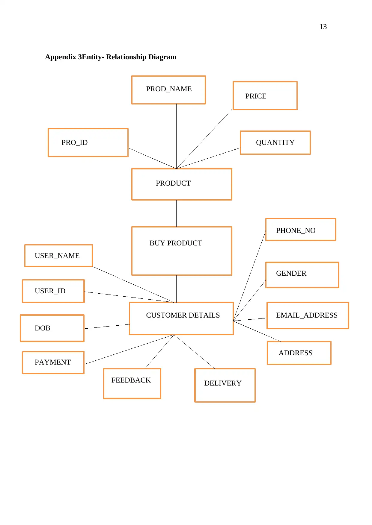
Entity- Relationship Diagram
Entity Relationship Diagram used to define the relationships of entities which are present in
the database. It is also known as the logical structure of databases [9]. With the help of entity
relationship diagram, a relational database can be created easily [10].
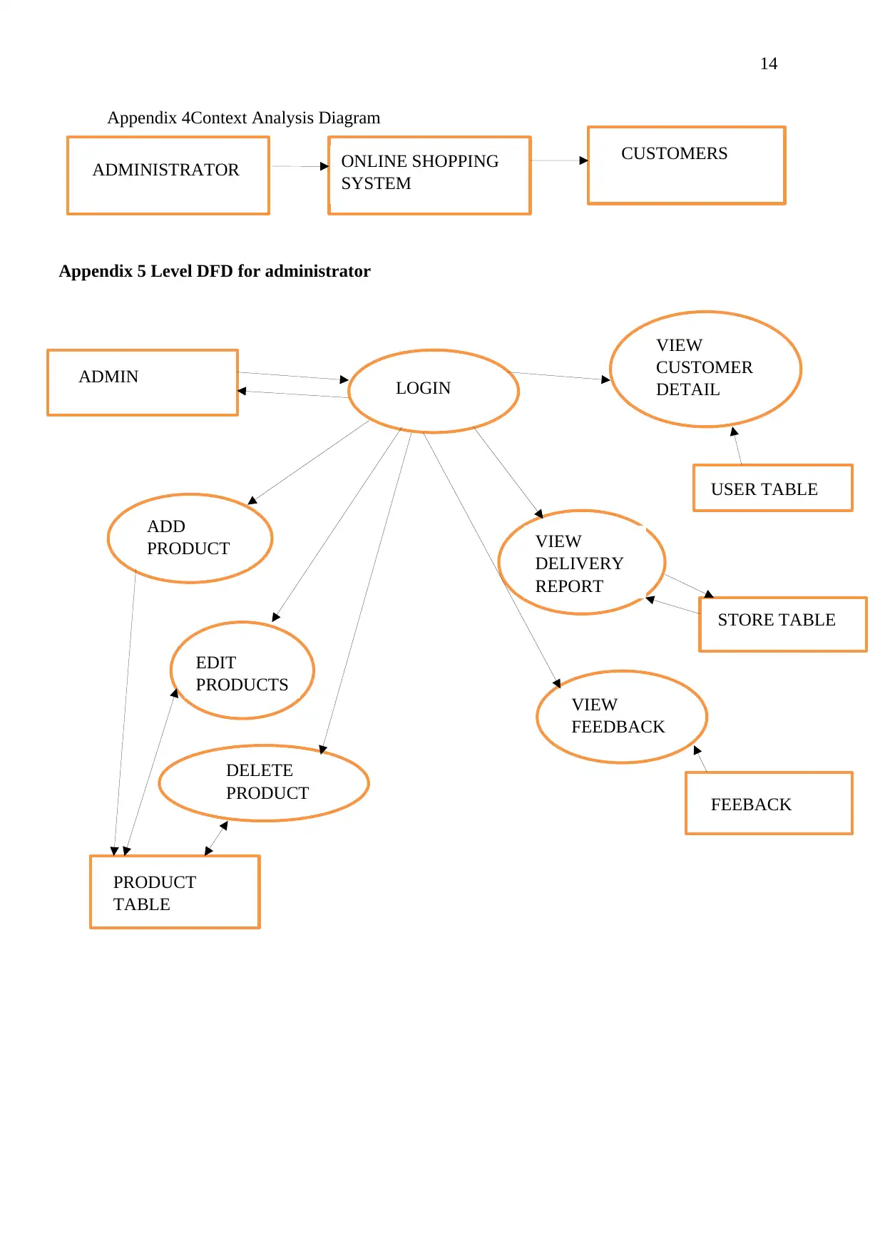
Context Analysis Diagram
Context Analysis Diagrams represents the system as a high-level process and the relationship
of the system with external entities. It is also known as context level data-flow diagram.
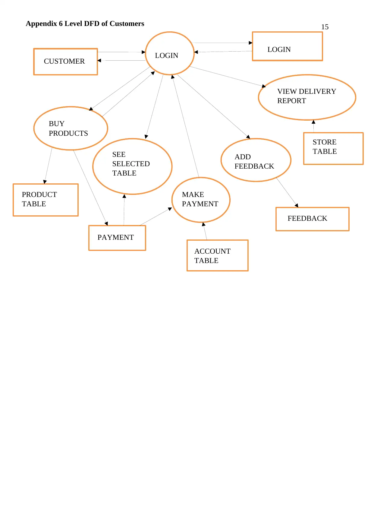
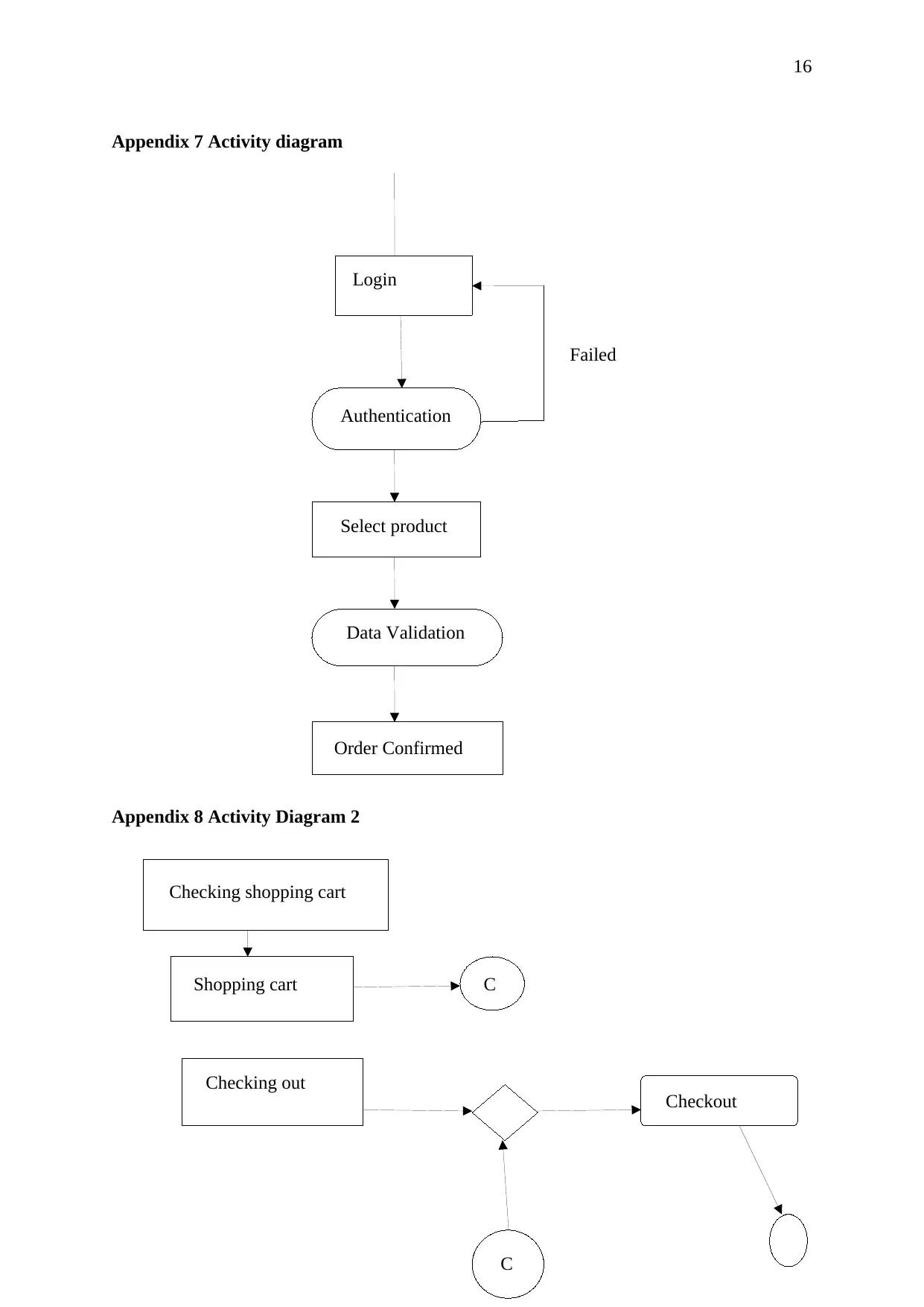
Data Flow Diagram
Data Flow Diagram describes how the information flows in a system. They form a basic part
of system analysis and design [11].
Class Diagram
Class Diagrams are types of diagrams which describe the structure of the project as the
system’s classes are shown along with their attributes and methods and the type of
relationship between them.
Appendix 1 - Class Diagram
Administrator LOGIN SYSTEM
+Name: String +Name: string +Status: Boolean
12
+Password: String +Password: string +login ()
+get_value ( ) +Access () +logout (t)
+set_value ( ) +Access Type () +members ()
+login (t) +list_products ()
+update ()
+display ()
Appendix 2USE-CASE DIAGRAM
Login
Manage Customer
Database
Browse
category
View/delete
entries
Add/remove
item from cart
Shipping
Order
Payment
13
Appendix 3Entity- Relationship Diagram
PRODUCT
PRO_ID
PROD_NAME PRICE
QUANTITY
BUY PRODUCT
USER_NAME
USER_ID
CUSTOMER DETAILS
PHONE_NO
GENDER
EMAIL_ADDRESS
DOB
PAYMENT
FEEDBACK DELIVERY
ADDRESS
Appendix 3Entity- Relationship Diagram
PRODUCT
PRO_ID
PROD_NAME PRICE
QUANTITY
BUY PRODUCT
USER_NAME
USER_ID
CUSTOMER DETAILS
PHONE_NO
GENDER
EMAIL_ADDRESS
DOB
PAYMENT
FEEDBACK DELIVERY
ADDRESS
Paraphrase This Document
Need a fresh take? Get an instant paraphrase of this document with our AI Paraphraser
14
Appendix 4Context Analysis Diagram
ADMINISTRATOR ONLINE SHOPPING
SYSTEM
CUSTOMERS
ADMIN LOGIN
VIEW
CUSTOMER
DETAIL
ADD
PRODUCT
S
EDIT
PRODUCTS
DELETE
PRODUCT
S
USER TABLE
STORE TABLE
VIEW
DELIVERY
REPORT
PRODUCT
TABLE
FEEBACK
VIEW
FEEDBACK
Appendix 5 Level DFD for administrator
Appendix 4Context Analysis Diagram
ADMINISTRATOR ONLINE SHOPPING
SYSTEM
CUSTOMERS
ADMIN LOGIN
VIEW
CUSTOMER
DETAIL
ADD
PRODUCT
S
EDIT
PRODUCTS
DELETE
PRODUCT
S
USER TABLE
STORE TABLE
VIEW
DELIVERY
REPORT
PRODUCT
TABLE
FEEBACK
VIEW
FEEDBACK
Appendix 5 Level DFD for administrator
15
CUSTOMER LOGIN
BUY
PRODUCTS
PRODUCT
TABLE
PAYMENT
TABLE
STORE
TABLE
LOGIN
VIEW DELIVERY
REPORT
SEE
SELECTED
TABLE
MAKE
PAYMENT
ACCOUNT
TABLE
ADD
FEEDBACK
FEEDBACK
Appendix 6 Level DFD of Customers
CUSTOMER LOGIN
BUY
PRODUCTS
PRODUCT
TABLE
PAYMENT
TABLE
STORE
TABLE
LOGIN
VIEW DELIVERY
REPORT
SEE
SELECTED
TABLE
MAKE
PAYMENT
ACCOUNT
TABLE
ADD
FEEDBACK
FEEDBACK
Appendix 6 Level DFD of Customers
16
Appendix 7 Activity diagram
Appendix 8 Activity Diagram 2
Login
Authentication
Select product
Data Validation
Order Confirmed
Failed
Checking shopping cart
Shopping cart C
Checking out
C
Checkout
Appendix 7 Activity diagram
Appendix 8 Activity Diagram 2
Login
Authentication
Select product
Data Validation
Order Confirmed
Failed
Checking shopping cart
Shopping cart C
Checking out
C
Checkout
Secure Best Marks with AI Grader
Need help grading? Try our AI Grader for instant feedback on your assignments.
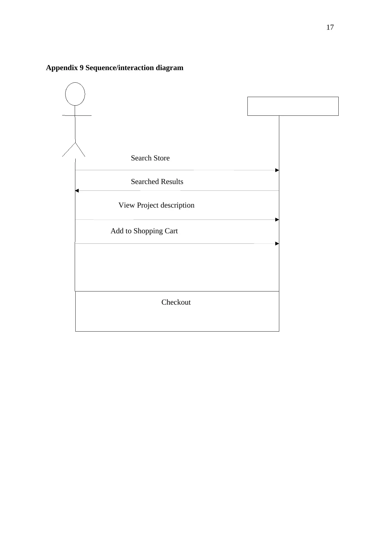
17
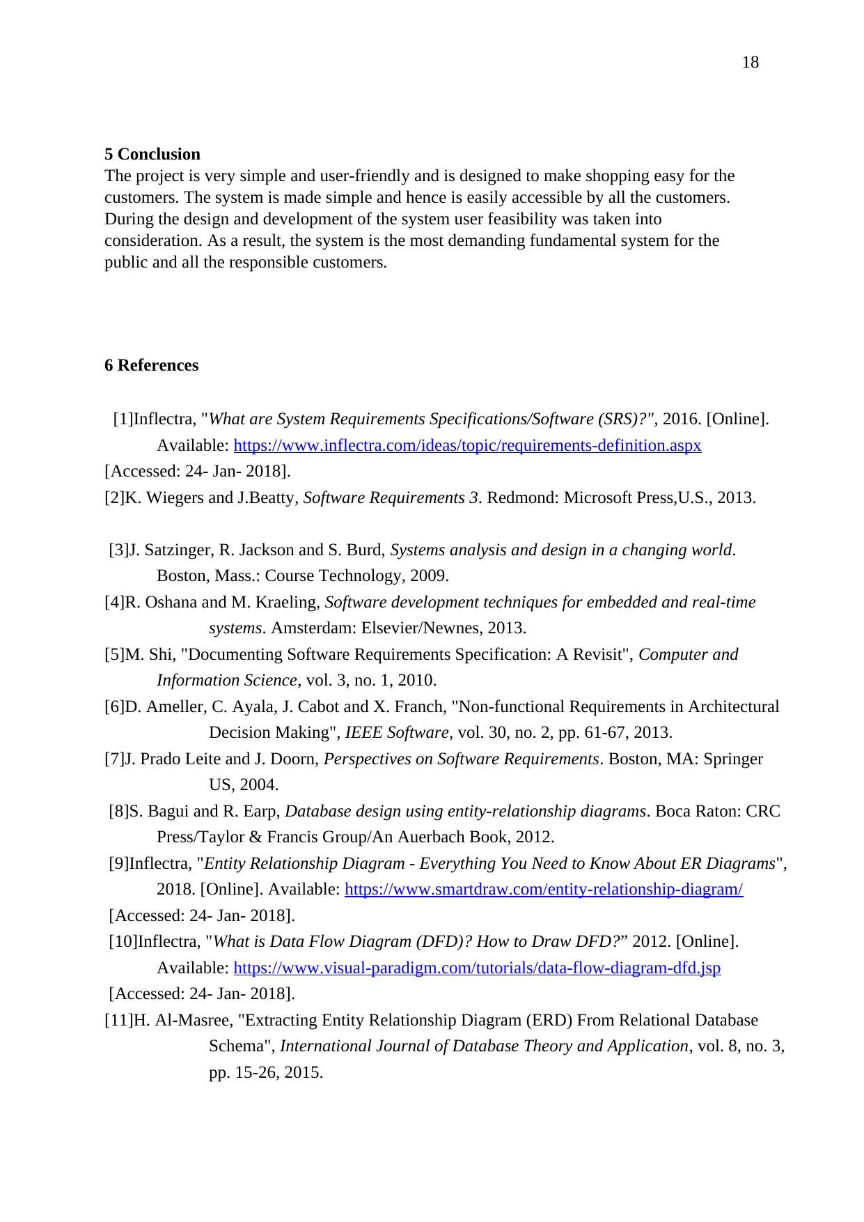
Appendix 9 Sequence/interaction diagram
Search Store
Searched Results
View Project description
Add to Shopping Cart
Checkout
Appendix 9 Sequence/interaction diagram
Search Store
Searched Results
View Project description
Add to Shopping Cart
Checkout
18
5 Conclusion
The project is very simple and user-friendly and is designed to make shopping easy for the
customers. The system is made simple and hence is easily accessible by all the customers.
During the design and development of the system user feasibility was taken into
consideration. As a result, the system is the most demanding fundamental system for the
public and all the responsible customers.
6 References
[1]Inflectra, "What are System Requirements Specifications/Software (SRS)?", 2016. [Online].
Available: https://www.inflectra.com/ideas/topic/requirements-definition.aspx
[Accessed: 24- Jan- 2018].
[2]K. Wiegers and J.Beatty, Software Requirements 3. Redmond: Microsoft Press,U.S., 2013.
[3]J. Satzinger, R. Jackson and S. Burd, Systems analysis and design in a changing world.
Boston, Mass.: Course Technology, 2009.
[4]R. Oshana and M. Kraeling, Software development techniques for embedded and real-time
systems. Amsterdam: Elsevier/Newnes, 2013.
[5]M. Shi, "Documenting Software Requirements Specification: A Revisit", Computer and
Information Science, vol. 3, no. 1, 2010.
[6]D. Ameller, C. Ayala, J. Cabot and X. Franch, "Non-functional Requirements in Architectural
Decision Making", IEEE Software, vol. 30, no. 2, pp. 61-67, 2013.
[7]J. Prado Leite and J. Doorn, Perspectives on Software Requirements. Boston, MA: Springer
US, 2004.
[8]S. Bagui and R. Earp, Database design using entity-relationship diagrams. Boca Raton: CRC
Press/Taylor & Francis Group/An Auerbach Book, 2012.
[9]Inflectra, "Entity Relationship Diagram - Everything You Need to Know About ER Diagrams",
2018. [Online]. Available: https://www.smartdraw.com/entity-relationship-diagram/
[Accessed: 24- Jan- 2018].
[10]Inflectra, "What is Data Flow Diagram (DFD)? How to Draw DFD?” 2012. [Online].
Available: https://www.visual-paradigm.com/tutorials/data-flow-diagram-dfd.jsp
[Accessed: 24- Jan- 2018].
[11]H. Al-Masree, "Extracting Entity Relationship Diagram (ERD) From Relational Database
Schema", International Journal of Database Theory and Application, vol. 8, no. 3,
pp. 15-26, 2015.

19
1 out of 19
Related Documents
Your All-in-One AI-Powered Toolkit for Academic Success.
+13062052269
info@desklib.com
Available 24*7 on WhatsApp / Email
![[object Object]](/_next/static/media/star-bottom.7253800d.svg)
Unlock your academic potential
© 2024 | Zucol Services PVT LTD | All rights reserved.


