Assignment for Advanced Energy Conversion Systems (42091)
15 Pages2004 Words18 Views
Added on 2022-09-15
Assignment for Advanced Energy Conversion Systems (42091)
Added on 2022-09-15
ShareRelated Documents
Advanced Energy Conversion Systems (42091)
Assignment: 1 (part 1)
Submitted to
Submitted from
1 | P a g e
Assignment: 1 (part 1)
Submitted to
Submitted from
1 | P a g e
Contents
1. Introduction:........................................................................................................ 3
2. Construction........................................................................................................ 3
3. Basic driving principle of BLDC...............................................................................4
4. Basic analytical formulas for motor performance analysis................................................8
5. Calculations of some steady-state performance..............................................................10
6. A Simulink model of BLDC............................................................................... 12
7. Dynamic and steady-state performance........................................................................14
Summery................................................................................................................ 15
References.............................................................................................................. 15
List of figures
Figure 1 Classification of BLDC motors based on direction of magnetic flux. (A) Radial-flux (inner
rotor), (B) radial-flux (outer rotor)...................................................................................3
Figure 2 BLDC drive system.......................................................................................... 4
Figure 3 sequence of triggering.............................................................................5
Figure 4 Waveforms.................................................................................................... 6
Figure 5 FOC control.............................................................................................. 7
Figure 6 Dynamic per phase equivalent circuit....................................................................7
Figure 7 Steady state equivalent circuit................................................................8
Figure 8 Simulation.............................................................................................. 11
Figure 9 speed and torque...................................................................................11
Figure 10 Machine and Control Parameters.........................................................12
Figure 11(A) Speed curve.................................................................................... 13
Figure 11(B) Phase
Current...............................................................................................................
............ 13 Figure 11(C)
Torque...............................................................................................................
........................ 13
2 | P a g e
BASIC OF BLDC
(BRUSHLESS D.C MOTOR)
1. Introduction:
BLDC motor industry is world larges growing motor industry because it’s use and advantages
over other motors for industrial, automation, aerospace, consumer, medical and instrumental
small devices.
As name implies, BLDC motor is brushless motor and it have more upper hand than DC
motors few are discussed below:
1. Less maintenance requirement.
2. High efficiency.
3. Higher speed variation.
4. Long operation life.
5. Less noise.
In addition, the motor supply high torque in small size effectively, and this think justify in
operation in construction.
2. Construction
BLDC motor classified according to stator windings and motor design.
According to the stator winding:
Single-phase, two phase, three phase and multi-phase. The single-phase BLDC motor generally
used in low power applications, up to 10 W, such as small fans. This motor has simple driving
circuit, simple structure and low cost as well as low maintenance. However, the drawback of this
type of motor is that motors are unidirectional and there is no starting torque hence secondary
part, which is produce reluctance torque is necessary for start the motor.
Multi-phase BLDC motor has four phase or above four-phase. These types of motors are highly
reliable so majorly used in military and aerospace applications. The reliability is high compared to
low phase winding motors.
According to the motor design
Based on motor design, further classified in terms of direction of magnetic flux: radial flux type
and axial flux type.
In radial flux type of motor construction, the rotor magnetic flux crosses the air gap in a radial
direction. This type of motor can be either an outer rotor type or an inner rotor type as shown in
Figure 1 (A and B).
Inner rotor design has a lot of advantages than outer rotor design. Such as, higher heat dissipating
capacity, high torque to inertia ratio and low rotor inertia. However, motor produce high vibration
and noise.
Outer rotor design means the rotor is in cylindrical shape with a shaft where the bearings are
mounted. The rotor magnets rotate around the stator windings which located in the iron core of
the motor. It has high rotor inertia. Also, motor rotate at constant speed. These types of motor
3 | P a g e
used in cooling fans, washing machines and disk drives. The advantages over inner rotor design
that it produces less vibration and noise compared to inner rotor.
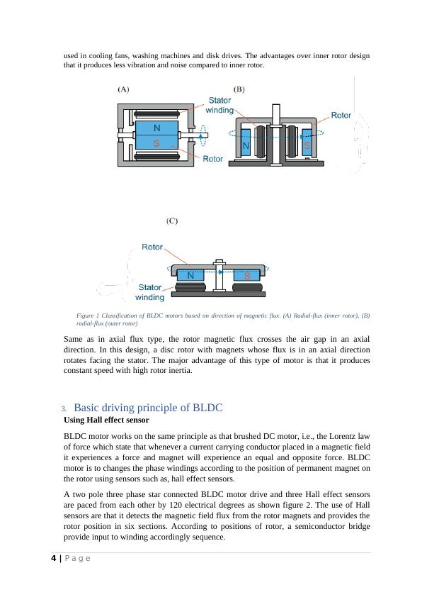
Figure 1 Classification of BLDC motors based on direction of magnetic flux. (A) Radial-flux (inner rotor), (B)
radial-flux (outer rotor)
Same as in axial flux type, the rotor magnetic flux crosses the air gap in an axial
direction. In this design, a disc rotor with magnets whose flux is in an axial direction
rotates facing the stator. The major advantage of this type of motor is that it produces
constant speed with high rotor inertia.
3. Basic driving principle of BLDC
Using Hall effect sensor
BLDC motor works on the same principle as that brushed DC motor, i.e., the Lorentz law
of force which state that whenever a current carrying conductor placed in a magnetic field
it experiences a force and magnet will experience an equal and opposite force. BLDC
motor is to changes the phase windings according to the position of permanent magnet on
the rotor using sensors such as, hall effect sensors.
A two pole three phase star connected BLDC motor drive and three Hall effect sensors
are paced from each other by 120 electrical degrees as shown figure 2. The use of Hall
sensors are that it detects the magnetic field flux from the rotor magnets and provides the
rotor position in six sections. According to positions of rotor, a semiconductor bridge
provide input to winding accordingly sequence.
4 | P a g e
that it produces less vibration and noise compared to inner rotor.
Figure 1 Classification of BLDC motors based on direction of magnetic flux. (A) Radial-flux (inner rotor), (B)
radial-flux (outer rotor)
Same as in axial flux type, the rotor magnetic flux crosses the air gap in an axial
direction. In this design, a disc rotor with magnets whose flux is in an axial direction
rotates facing the stator. The major advantage of this type of motor is that it produces
constant speed with high rotor inertia.
3. Basic driving principle of BLDC
Using Hall effect sensor
BLDC motor works on the same principle as that brushed DC motor, i.e., the Lorentz law
of force which state that whenever a current carrying conductor placed in a magnetic field
it experiences a force and magnet will experience an equal and opposite force. BLDC
motor is to changes the phase windings according to the position of permanent magnet on
the rotor using sensors such as, hall effect sensors.
A two pole three phase star connected BLDC motor drive and three Hall effect sensors
are paced from each other by 120 electrical degrees as shown figure 2. The use of Hall
sensors are that it detects the magnetic field flux from the rotor magnets and provides the
rotor position in six sections. According to positions of rotor, a semiconductor bridge
provide input to winding accordingly sequence.
4 | P a g e
End of preview
Want to access all the pages? Upload your documents or become a member.
Related Documents
42091: Advanced Energy Conversion Systems Assignment 2022lg...
|12
|1670
|26
Competency Demonstration Report (CDR)lg...
|8
|1614
|95
Synchronous Machines - Types, Operation, Phasor Diagram, Torque and Powerlg...
|3
|535
|313
Hydrogenerator basic design calculation PDFlg...
|29
|7112
|321
Classifications of DC Motorslg...
|15
|1933
|121
Theoretical Background Electrical Engineeringlg...
|9
|1452
|51