Advanced Robotics- Project Report
VerifiedAdded on 2022/07/28
|12
|2739
|31
AI Summary
I need matlab program and solutions for sub section 2.1 and sub section 2.2
Contribute Materials
Your contribution can guide someone’s learning journey. Share your
documents today.
ME5402/EE5106/EE5064 ADVANCED ROBOTICS
Part II: Dynamics and Control
Mini Project I
Student Name –
Student ID –
Mechanical Engg.
Robotics
Part II: Dynamics and Control
Mini Project I
Student Name –
Student ID –
Mechanical Engg.
Robotics
Secure Best Marks with AI Grader
Need help grading? Try our AI Grader for instant feedback on your assignments.
Contents
Introduction:..........................................................................................................................................1
2-1: Modeling and Animation of the Robotic Arm................................................................................3
1. Literature review : Robot design and virtual robot simulation.......................................................3
2. D-H model of the robotic arm in Figures 1 and 2, and derivation of the Lagrange-Euler
equations............................................................................................................................................3
3. Kinematic and dynamic equations.................................................................................................4
4. Control design...............................................................................................................................4
2-2: Robust Control of the Robotic Arm...............................................................................................5
1. Literature review : Robust control of the robotic arm....................................................................5
2. D-H model of the robotic arm in Figures 1 and 2, and derivation of the Lagrange-Euler
equations............................................................................................................................................6
3. Design of Force Control and Position Control (Hybrid Force / Position Control) for the robotic
arm....................................................................................................................................................7
4. Design of Robust Control for the robotic arm and discussion on the robustness effect of different
selection of terms or functions or algorithms imposed on the controller designed.............................7
5. Simulation : Robust Control performance of the robotic arm using MATLAB software...............7
References.............................................................................................................................................9
Introduction:
The robots making use of artificial intelligence are becoming popular these days. They can be
used in a variety of applications like the automation of industrial processes. The UR
( Universal Robot ) is a robot having 6 degrees of freedom which is capable of working in 3
dimensional space. Hence, it holds a special significance. Its study can be done in 2 ways.
One is robot kinematics and the other is robot dynamics. The robot kinematics consists of the
forward kinematics and inverse kinematics ( which study the relationship between the joint
variable space and the end - effector position and orientation ). The robot dynamics consists
of robot controller design ( which study the relationship between the robot motion and the
forces/torques).
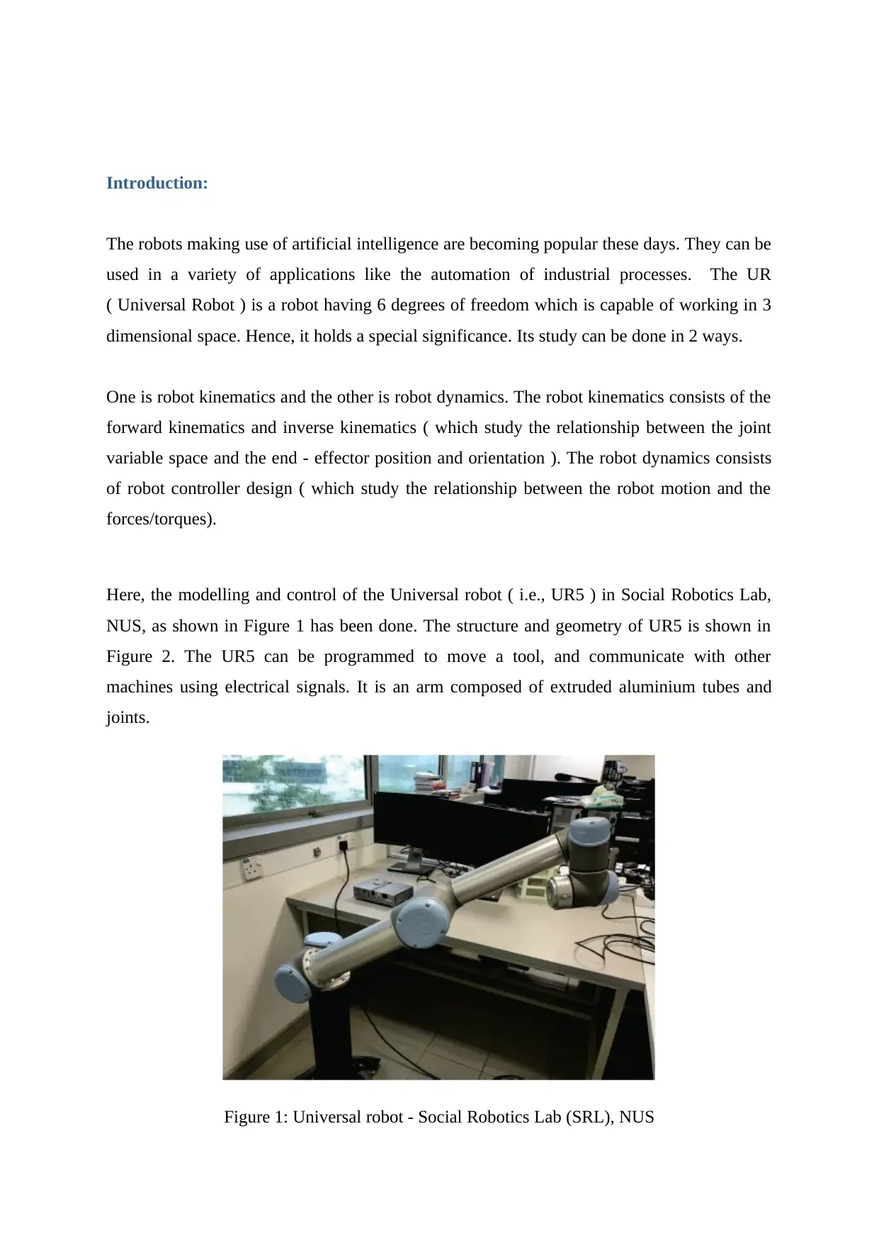
Here, the modelling and control of the Universal robot ( i.e., UR5 ) in Social Robotics Lab,
NUS, as shown in Figure 1 has been done. The structure and geometry of UR5 is shown in
Figure 2. The UR5 can be programmed to move a tool, and communicate with other
machines using electrical signals. It is an arm composed of extruded aluminium tubes and
joints.
Figure 1: Universal robot - Social Robotics Lab (SRL), NUS
The robots making use of artificial intelligence are becoming popular these days. They can be
used in a variety of applications like the automation of industrial processes. The UR
( Universal Robot ) is a robot having 6 degrees of freedom which is capable of working in 3
dimensional space. Hence, it holds a special significance. Its study can be done in 2 ways.
One is robot kinematics and the other is robot dynamics. The robot kinematics consists of the
forward kinematics and inverse kinematics ( which study the relationship between the joint
variable space and the end - effector position and orientation ). The robot dynamics consists
of robot controller design ( which study the relationship between the robot motion and the
forces/torques).
Here, the modelling and control of the Universal robot ( i.e., UR5 ) in Social Robotics Lab,
NUS, as shown in Figure 1 has been done. The structure and geometry of UR5 is shown in
Figure 2. The UR5 can be programmed to move a tool, and communicate with other
machines using electrical signals. It is an arm composed of extruded aluminium tubes and
joints.
Figure 1: Universal robot - Social Robotics Lab (SRL), NUS
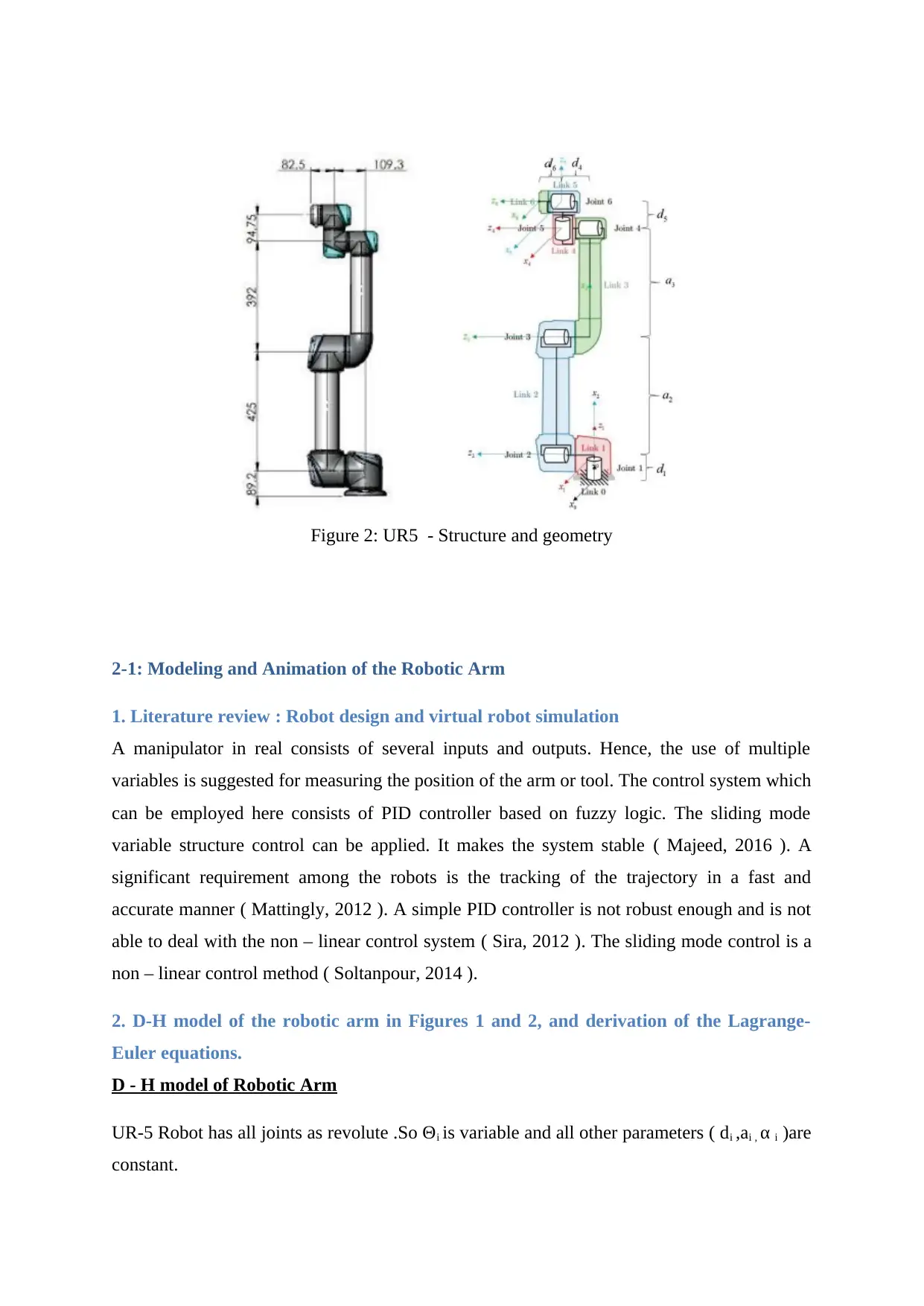
Figure 2: UR5 - Structure and geometry
2-1: Modeling and Animation of the Robotic Arm
1. Literature review : Robot design and virtual robot simulation
A manipulator in real consists of several inputs and outputs. Hence, the use of multiple
variables is suggested for measuring the position of the arm or tool. The control system which
can be employed here consists of PID controller based on fuzzy logic. The sliding mode
variable structure control can be applied. It makes the system stable ( Majeed, 2016 ). A
significant requirement among the robots is the tracking of the trajectory in a fast and
accurate manner ( Mattingly, 2012 ). A simple PID controller is not robust enough and is not
able to deal with the non – linear control system ( Sira, 2012 ). The sliding mode control is a
non – linear control method ( Soltanpour, 2014 ).
2. D-H model of the robotic arm in Figures 1 and 2, and derivation of the Lagrange-
Euler equations.
D - H model of Robotic Arm
UR-5 Robot has all joints as revolute .So Θi is variable and all other parameters ( di ,ai , α i )are
constant.
Secure Best Marks with AI Grader
Need help grading? Try our AI Grader for instant feedback on your assignments.
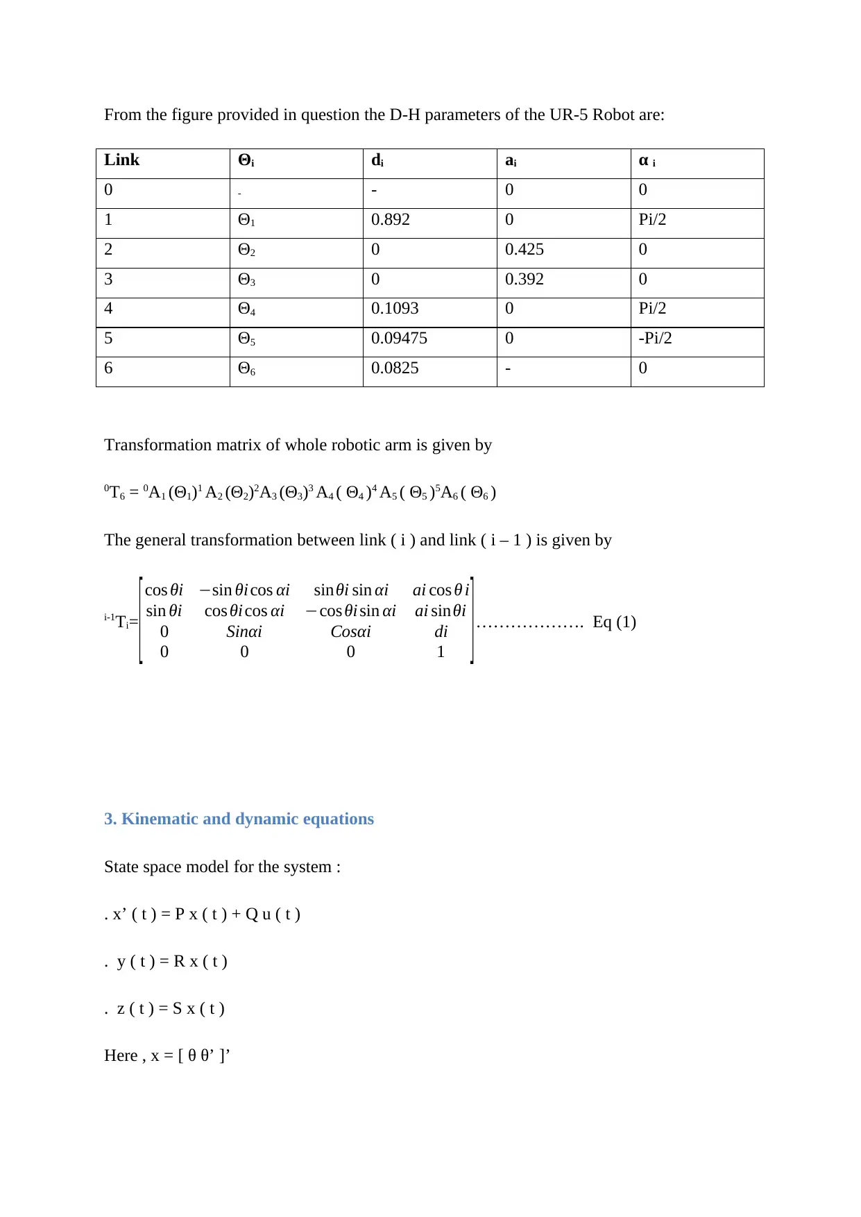
From the figure provided in question the D-H parameters of the UR-5 Robot are:
Link Θi di ai α i
0 - - 0 0
1 Θ1 0.892 0 Pi/2
2 Θ2 0 0.425 0
3 Θ3 0 0.392 0
4 Θ4 0.1093 0 Pi/2
5 Θ5 0.09475 0 -Pi/2
6 Θ6 0.0825 - 0
Transformation matrix of whole robotic arm is given by
0T6 = 0A1 (Θ1)1 A2 (Θ2)2A3 (Θ3)3 A4 ( Θ4 )4 A5 ( Θ5 )5A6 ( Θ6 )
The general transformation between link ( i ) and link ( i – 1 ) is given by
i-1Ti=
[cos θi −sin θi cos αi sinθi sin αi ai cos θ i
sin θi cos θi cos αi −cos θi sin αi ai sinθi
0 Sinαi Cosαi di
0 0 0 1 ]………………. Eq (1)
3. Kinematic and dynamic equations
State space model for the system :
. x’ ( t ) = P x ( t ) + Q u ( t )
. y ( t ) = R x ( t )
. z ( t ) = S x ( t )
Here , x = [ θ θ’ ]’
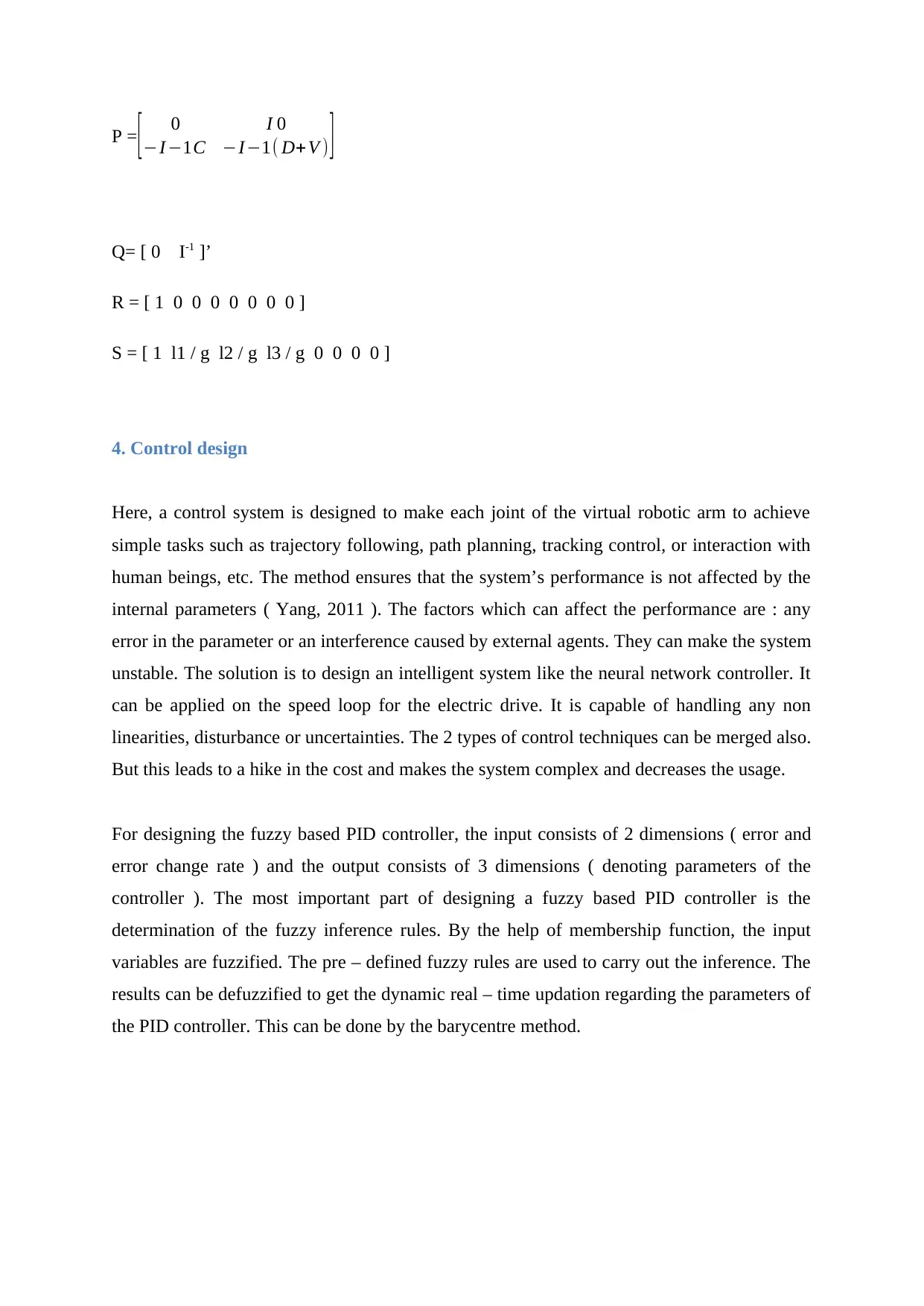
P =[ 0 I 0
−I−1C −I−1( D+ V ) ]
Q= [ 0 I-1 ]’
R = [ 1 0 0 0 0 0 0 0 ]
S = [ 1 l1 / g l2 / g l3 / g 0 0 0 0 ]
4. Control design
Here, a control system is designed to make each joint of the virtual robotic arm to achieve
simple tasks such as trajectory following, path planning, tracking control, or interaction with
human beings, etc. The method ensures that the system’s performance is not affected by the
internal parameters ( Yang, 2011 ). The factors which can affect the performance are : any
error in the parameter or an interference caused by external agents. They can make the system
unstable. The solution is to design an intelligent system like the neural network controller. It
can be applied on the speed loop for the electric drive. It is capable of handling any non
linearities, disturbance or uncertainties. The 2 types of control techniques can be merged also.
But this leads to a hike in the cost and makes the system complex and decreases the usage.
For designing the fuzzy based PID controller, the input consists of 2 dimensions ( error and
error change rate ) and the output consists of 3 dimensions ( denoting parameters of the
controller ). The most important part of designing a fuzzy based PID controller is the
determination of the fuzzy inference rules. By the help of membership function, the input
variables are fuzzified. The pre – defined fuzzy rules are used to carry out the inference. The
results can be defuzzified to get the dynamic real – time updation regarding the parameters of
the PID controller. This can be done by the barycentre method.
2-2: Robust Control of the Robotic Arm
1. Literature review : Robust control of the robotic arm.
A discrete time controller can be used for optimizing the performance of the system, if the
requirements for robustness are mentioned. The manipulator used for industries consists of 6
links which are mounted serially ( Khairudin, 2011 ). They can be controlled using the
electrical motors with the gears. It consists of 6 degrees of freedom ( DOF ). For the DOF
manipulator, the dynamics change very fast due to the fast movement of robot arms in the
range specified. There is a strong dynamic coupling between the arms. The arms have an
elastic nature ( Guo, 2015 ). The gear has non – linear behaviour ( in terms of backlash,
friction and stiffness / elasticity ).
2. D-H model of the robotic arm in Figures 1 and 2, and derivation of the Lagrange-
Euler equations.
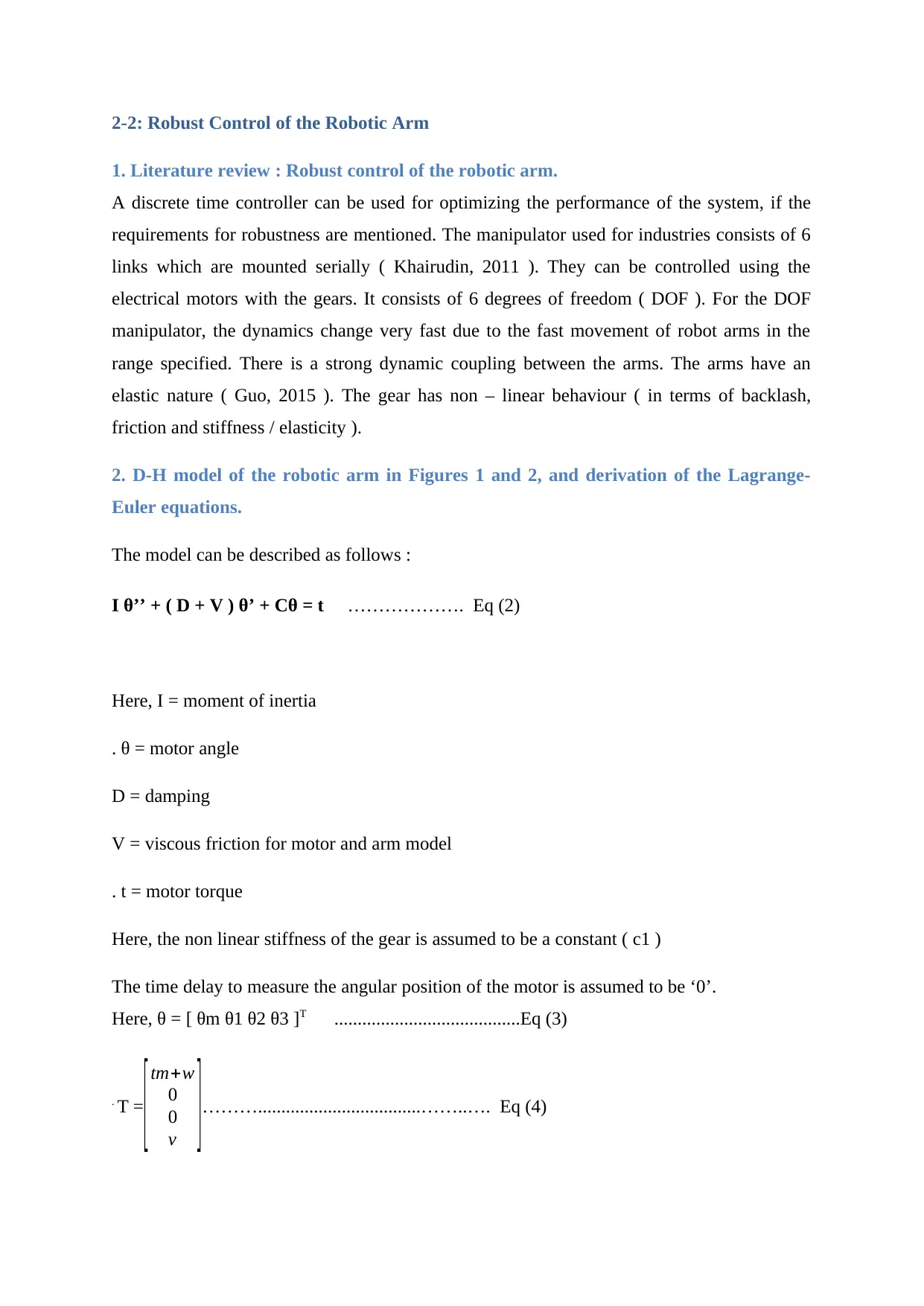
The model can be described as follows :
I θ’’ + ( D + V ) θ’ + Cθ = t ………………. Eq (2)
Here, I = moment of inertia
. θ = motor angle
D = damping
V = viscous friction for motor and arm model
. t = motor torque
Here, the non linear stiffness of the gear is assumed to be a constant ( c1 )
The time delay to measure the angular position of the motor is assumed to be ‘0’.
Here, θ = [ θm θ1 θ2 θ3 ]T ........................................Eq (3)
. T =
[tm+w
0
0
v ]………...................................……..…. Eq (4)
1. Literature review : Robust control of the robotic arm.
A discrete time controller can be used for optimizing the performance of the system, if the
requirements for robustness are mentioned. The manipulator used for industries consists of 6
links which are mounted serially ( Khairudin, 2011 ). They can be controlled using the
electrical motors with the gears. It consists of 6 degrees of freedom ( DOF ). For the DOF
manipulator, the dynamics change very fast due to the fast movement of robot arms in the
range specified. There is a strong dynamic coupling between the arms. The arms have an
elastic nature ( Guo, 2015 ). The gear has non – linear behaviour ( in terms of backlash,
friction and stiffness / elasticity ).
2. D-H model of the robotic arm in Figures 1 and 2, and derivation of the Lagrange-
Euler equations.
The model can be described as follows :
I θ’’ + ( D + V ) θ’ + Cθ = t ………………. Eq (2)
Here, I = moment of inertia
. θ = motor angle
D = damping
V = viscous friction for motor and arm model
. t = motor torque
Here, the non linear stiffness of the gear is assumed to be a constant ( c1 )
The time delay to measure the angular position of the motor is assumed to be ‘0’.
Here, θ = [ θm θ1 θ2 θ3 ]T ........................................Eq (3)
. T =
[tm+w
0
0
v ]………...................................……..…. Eq (4)
Paraphrase This Document
Need a fresh take? Get an instant paraphrase of this document with our AI Paraphraser
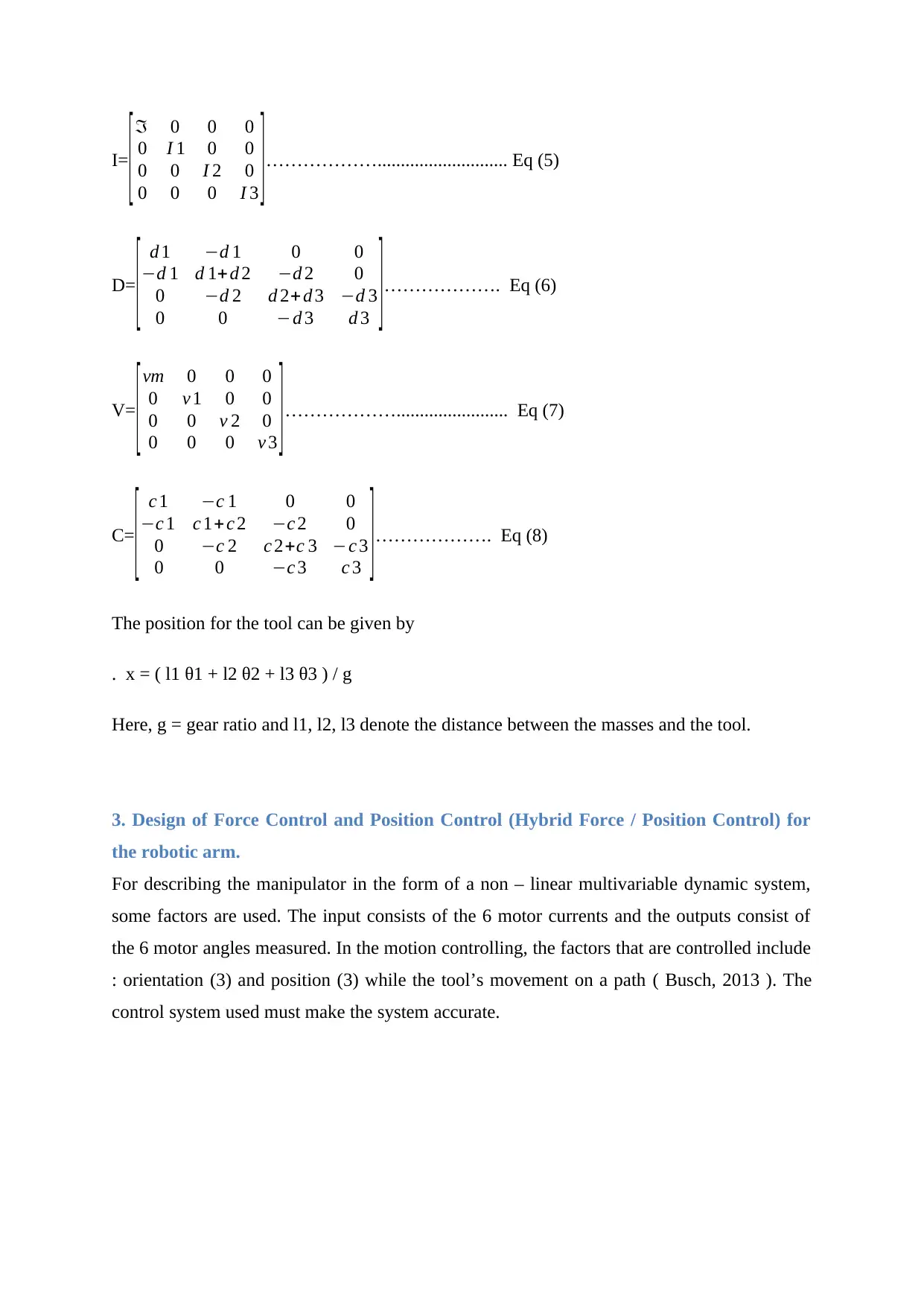
I=
[ℑ 0 0 0
0 I 1 0 0
0 0 I 2 0
0 0 0 I 3 ]………………............................ Eq (5)
D=
[ d 1 −d 1 0 0
−d 1 d 1+d 2 −d 2 0
0 −d 2 d 2+ d 3 −d 3
0 0 −d 3 d 3 ]………………. Eq (6)
V=
[ vm 0 0 0
0 v 1 0 0
0 0 v 2 0
0 0 0 v 3 ]………………........................ Eq (7)
C=
[ c 1 −c 1 0 0
−c 1 c 1+ c 2 −c 2 0
0 −c 2 c 2+c 3 −c 3
0 0 −c 3 c 3 ]………………. Eq (8)
The position for the tool can be given by
. x = ( l1 θ1 + l2 θ2 + l3 θ3 ) / g
Here, g = gear ratio and l1, l2, l3 denote the distance between the masses and the tool.
3. Design of Force Control and Position Control (Hybrid Force / Position Control) for
the robotic arm.
For describing the manipulator in the form of a non – linear multivariable dynamic system,
some factors are used. The input consists of the 6 motor currents and the outputs consist of
the 6 motor angles measured. In the motion controlling, the factors that are controlled include
: orientation (3) and position (3) while the tool’s movement on a path ( Busch, 2013 ). The
control system used must make the system accurate.
4. Design of Robust Control for the robotic arm and discussion on the robustness effect
of different selection of terms or functions or algorithms imposed on the controller
designed
For simulating the system, the SISO model can be used. It represents a robot axis which is
decoupled and whose operation is near an operating point fixed ( Abdullah, 2016 ). There is a
strong coupling between the 6 axis. The non – linear dynamic behaviour is neglected. The
gear’s non – linear friction has also been ignored ( Almusawi, 2016 ).
5. Simulation : Robust Control performance of the robotic arm using MATLAB
software
The robot arm configuration has been plotted. The DH parameter matrix is used. It makes use
of transformation matrices for computations. Here, a 6 – DOF robotic arm is presented. The
DH parameters are created in numerical or symbolic form for all the 6 frames.
The DH parameter frames which act as active joints are stored in j1. ‘bs1’ denotes the base
frame. ‘rDH’ is used for substituting all the symbolic joint names with the numerical values.
‘p1’ denotes the x, y, z positions for the base frame with respect to the world coordinates.
‘a12’ denotes the x, y, z angles for the base frame with respect to the world coordinates.
‘Twb’ is used to store the transformation matrix for base frame with respect to the world
coordinates. The size for x, y, z axis can be specified.
The function b1 is used to generate the transformation matrix for the base frame with respect
to the coordinates of the world. It takes the position ( 1 x 3 vector denoting x,y,z position for
base frame ) and angle ( 1 x 3 vector denoting x,y,z angle for base frame in radians ) as the
inputs.
The function b2 generates the forward kinematics transformation map matrix for the robotic
manipulator. It takes the DH ( Denavit – Hatenberg ) matrix as the input. DH consists of
symbolic as well as numerical elements. If the transformation matrix is required for the
complete arm, then EF is given by size of ( DH, 1 ). The transformation mapping matrix can
also be obtained from one frame to the other, which can be denoted by integers showing rows
in the DH matrix.
The function b3 is used for performing the transformation matrix inversion. It returns an
inverted matrix.
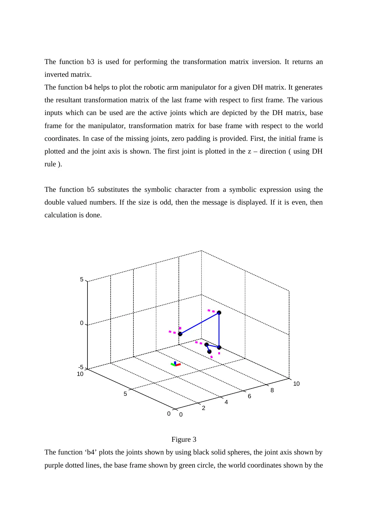
The function b4 helps to plot the robotic arm manipulator for a given DH matrix. It generates
the resultant transformation matrix of the last frame with respect to first frame. The various
inputs which can be used are the active joints which are depicted by the DH matrix, base
frame for the manipulator, transformation matrix for base frame with respect to the world
coordinates. In case of the missing joints, zero padding is provided. First, the initial frame is
plotted and the joint axis is shown. The first joint is plotted in the z – direction ( using DH
rule ).
The function b5 substitutes the symbolic character from a symbolic expression using the
double valued numbers. If the size is odd, then the message is displayed. If it is even, then
calculation is done.
0
2 4 6 8
10
0
5
10
-5
0
5
Figure 3
The function ‘b4’ plots the joints shown by using black solid spheres, the joint axis shown by
purple dotted lines, the base frame shown by green circle, the world coordinates shown by the
inverted matrix.
The function b4 helps to plot the robotic arm manipulator for a given DH matrix. It generates
the resultant transformation matrix of the last frame with respect to first frame. The various
inputs which can be used are the active joints which are depicted by the DH matrix, base
frame for the manipulator, transformation matrix for base frame with respect to the world
coordinates. In case of the missing joints, zero padding is provided. First, the initial frame is
plotted and the joint axis is shown. The first joint is plotted in the z – direction ( using DH
rule ).
The function b5 substitutes the symbolic character from a symbolic expression using the
double valued numbers. If the size is odd, then the message is displayed. If it is even, then
calculation is done.
0
2 4 6 8
10
0
5
10
-5
0
5
Figure 3
The function ‘b4’ plots the joints shown by using black solid spheres, the joint axis shown by
purple dotted lines, the base frame shown by green circle, the world coordinates shown by the
Secure Best Marks with AI Grader
Need help grading? Try our AI Grader for instant feedback on your assignments.
RGB lines which depict x, y, z axis. The plot obtained is shown in the Figure 3. ‘T16’
denotes the transformation matrix for frame 6 w.r.t. frame 1. ‘Tw6’ denotes the
transformation matrix for the frame 6 w.r.t. world frame.
References
Abdullah, S.C., Jusoh, M.A.M., Nawi, N.M. and Amari, M.D., 2016, November. Robot arm
simulation using 3D software application with 3D modeling, programming and simulation
support. In 2016 International Symposium on Micro-NanoMechatronics and Human Science
(MHS) (pp. 1-3). IEEE.
Almusawi, A.R., Dülger, L.C. and Kapucu, S., 2016, April. Robotic arm dynamic and
simulation with Virtual Reality Model (VRM). In 2016 International Conference on Control,
Decision and Information Technologies (CoDIT) (pp. 335-340). IEEE.
Busch, F., Wischniewski, S. and Deuse, J., 2013, June. Application of a character animation
SDK to design ergonomic human-robot-collaboration. In Proceedings of the 2nd
International Symposium on Digital Human Modeling (DHM) (pp. 1-7).
Guo, Q., Yu, T. and Jiang, D., 2015. Robust H∞ positional control of 2-DOF robotic arm
driven by electro-hydraulic servo system. ISA transactions, 59, pp.55-64.
Khairudin, M., Mohamed, Z. and Husain, A.R., 2011. Dynamic model and robust control of
flexible link robot manipulator. Telkomnika, 9(2), p.279.
Majeed, S.R. and Kuhnert, K.D., 2016. Automatic skinning of the simulated manipulator
robot arm. International Journal of Computer Graphics & Animation (IJCGA), 6(1).
Mattingly, W.A., Chang, D.J., Paris, R., Smith, N., Blevins, J. and Ouyang, M., 2012, July.
Robot design using Unity for computer games and robotic simulations. In 2012 17th
International Conference on Computer Games (CGAMES) (pp. 56-59). IEEE.
Sira-Ramirez, H. and Oliver-Salazar, M.A., 2012. On the robust control of buck-converter
DC-motor combinations. IEEE Transactions on Power Electronics, 28(8), pp.3912-3922.
Soltanpour, M.R., Otadolajam, P. and Khooban, M.H., 2014. Robust control strategy for
electrically driven robot manipulators: adaptive fuzzy sliding mode. IET Science,
Measurement & Technology, 9(3), pp.322-334.
Yang, Z.J., Fukushima, Y. and Qin, P., 2011. Decentralized adaptive robust control of robot
manipulators using disturbance observers. IEEE Transactions on Control Systems
Technology, 20(5), pp.1357-1365.
1 out of 12
Related Documents


Your All-in-One AI-Powered Toolkit for Academic Success.
+13062052269
info@desklib.com
Available 24*7 on WhatsApp / Email
![[object Object]](/_next/static/media/star-bottom.7253800d.svg)
Unlock your academic potential
© 2024 | Zucol Services PVT LTD | All rights reserved.