Faculty of Studies MECH204 Lab Report: Mechanics of Solids, Part A & B
VerifiedAdded on 2020/05/04
|8
|1219
|229
Practical Assignment
AI Summary
This lab report details a Mechanics of Solids experiment, focusing on torsion and shear tests. The experiment investigates the behavior of materials under torsional loading, using a torsion testing machine and various specimens. The report outlines the aims, objectives, equipment, and procedures, including the setup and data collection for different specimens. Part A focuses on torsion tests, recording torque and angle of twist. Part B involves shear experiments, measuring strain and calculating shear force and bending moment. The results section presents the collected data, calculations, and observations. Discussion includes discrepancies in torsion rigidity, comparison of torsional rigidity between samples, and potential sources of error. The report concludes with a summary of the experiment's findings and a discussion of the torsion test's applications. The report includes calculations for shear and bending forces, along with relevant equations and analysis of the stress-strain relationship. The report also includes references to relevant sources.
INSTITUTIONAL AFFILIATION
FACULTY OF STUDIES
COURSE CODE
COURSE NAME
MECHANICS OF SOLIDS: MECH204
LABORATORY (PART A AND PART B)
STUDENT NAME
STUDENT REGISTRATION NUMBER
TUTOR: Dr. Dane Turner
DATE OF SUBMISSION
FACULTY OF STUDIES
COURSE CODE
COURSE NAME
MECHANICS OF SOLIDS: MECH204
LABORATORY (PART A AND PART B)
STUDENT NAME
STUDENT REGISTRATION NUMBER
TUTOR: Dr. Dane Turner
DATE OF SUBMISSION
Paraphrase This Document
Need a fresh take? Get an instant paraphrase of this document with our AI Paraphraser
INTRODUCTION
In mechanics, the most commonly used structures are the torsional loaded shafts. A common
example is the drive shaft that is implemented in the back wheels of an automobile. The main
purpose of the shaft is to transmit torsion. In most mechanical structures, there are deformation
by elongation and/or compression. This brings out the idea of stress and strain. Uniaxial loading
results in deformation along the grid in a bid to elongate the lines in the direction of tensile
loading. The implication is the contraction of the lines perpendicular to the loading direction.
Usually the normal stress is denoted by the expression,
σ = P
A … stress
While the shear stress is thereafter denoted as,
τ = P
A … the loading hereis transverse rather thanextensional
The twisting moments or the torques are the forces that act through the length so as to cause
rotation. The example of the automobile highlighted above captures the shafts in the torsion of
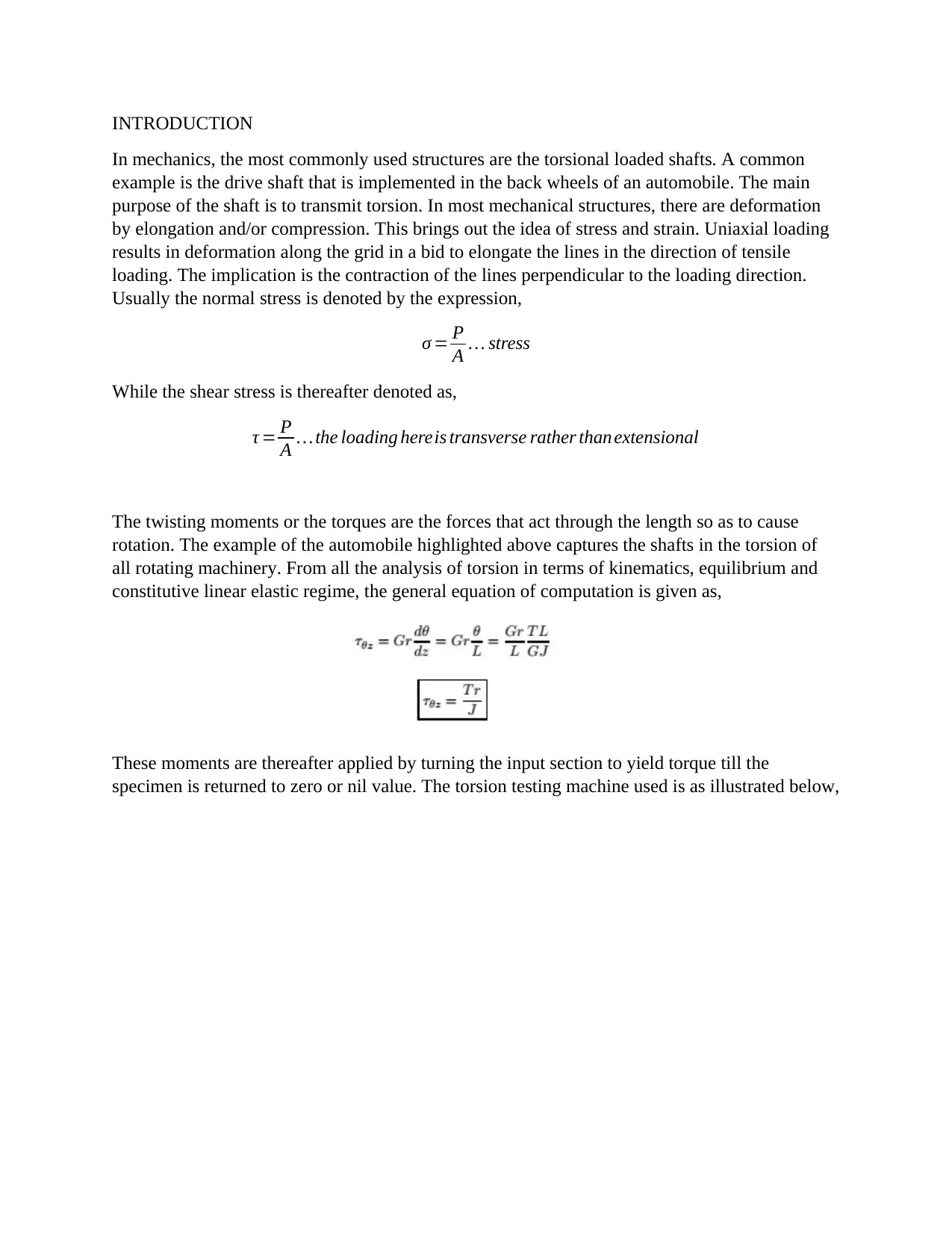
all rotating machinery. From all the analysis of torsion in terms of kinematics, equilibrium and
constitutive linear elastic regime, the general equation of computation is given as,
These moments are thereafter applied by turning the input section to yield torque till the
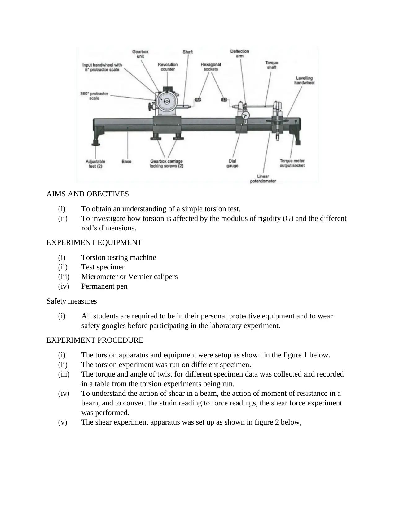
specimen is returned to zero or nil value. The torsion testing machine used is as illustrated below,
AIMS AND OBECTIVES
(i) To obtain an understanding of a simple torsion test.
(ii) To investigate how torsion is affected by the modulus of rigidity (G) and the different
rod’s dimensions.
EXPERIMENT EQUIPMENT
(i) Torsion testing machine
(ii) Test specimen
(iii) Micrometer or Vernier calipers
(iv) Permanent pen
Safety measures
(i) All students are required to be in their personal protective equipment and to wear
safety googles before participating in the laboratory experiment.
EXPERIMENT PROCEDURE
(i) The torsion apparatus and equipment were setup as shown in the figure 1 below.
(ii) The torsion experiment was run on different specimen.
(iii) The torque and angle of twist for different specimen data was collected and recorded
in a table from the torsion experiments being run.
(iv) To understand the action of shear in a beam, the action of moment of resistance in a
beam, and to convert the strain reading to force readings, the shear force experiment
was performed.
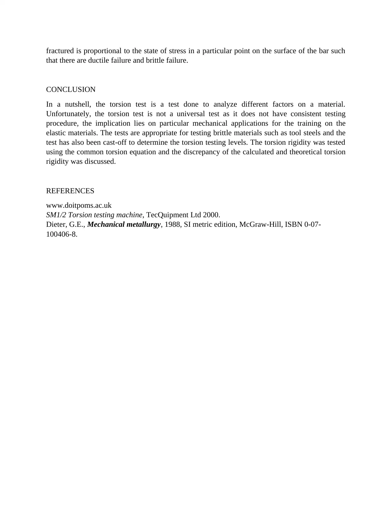
(v) The shear experiment apparatus was set up as shown in figure 2 below,
⊘ This is a preview!⊘
Do you want full access?
Subscribe today to unlock all pages.

Trusted by 1+ million students worldwide
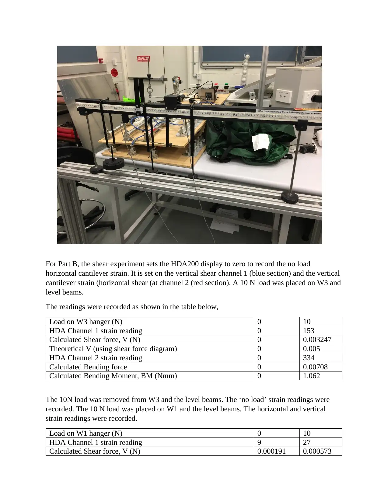
For Part B, the shear experiment sets the HDA200 display to zero to record the no load
horizontal cantilever strain. It is set on the vertical shear channel 1 (blue section) and the vertical
cantilever strain (horizontal shear (at channel 2 (red section). A 10 N load was placed on W3 and
level beams.
The readings were recorded as shown in the table below,
Load on W3 hanger (N) 0 10
HDA Channel 1 strain reading 0 153
Calculated Shear force, V (N) 0 0.003247
Theoretical V (using shear force diagram) 0 0.005
HDA Channel 2 strain reading 0 334
Calculated Bending force 0 0.00708
Calculated Bending Moment, BM (Nmm) 0 1.062
The 10N load was removed from W3 and the level beams. The ‘no load’ strain readings were
recorded. The 10 N load was placed on W1 and the level beams. The horizontal and vertical
strain readings were recorded.
Load on W1 hanger (N) 0 10
HDA Channel 1 strain reading 9 27
Calculated Shear force, V (N) 0.000191 0.000573
Paraphrase This Document
Need a fresh take? Get an instant paraphrase of this document with our AI Paraphraser
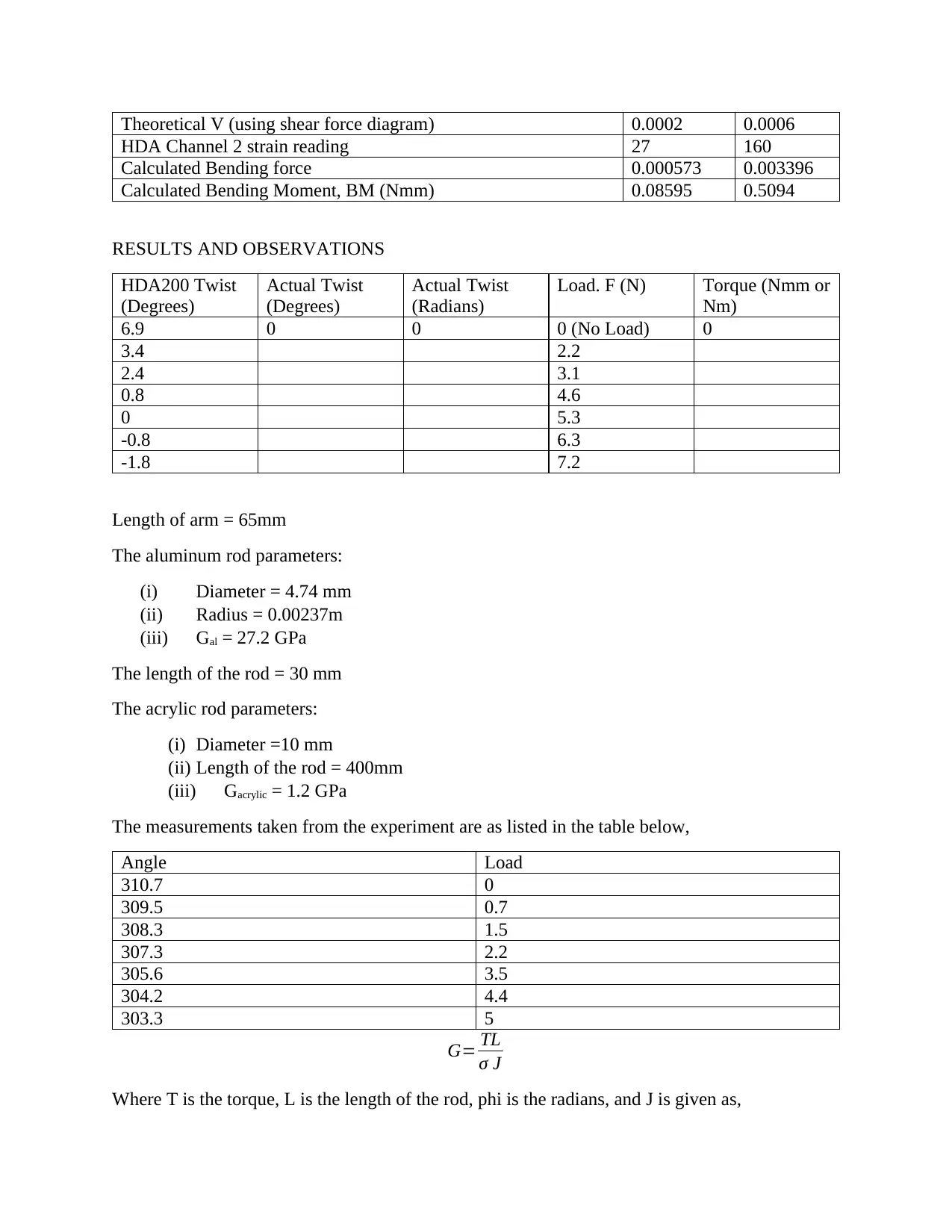
Theoretical V (using shear force diagram) 0.0002 0.0006
HDA Channel 2 strain reading 27 160
Calculated Bending force 0.000573 0.003396
Calculated Bending Moment, BM (Nmm) 0.08595 0.5094
RESULTS AND OBSERVATIONS
HDA200 Twist
(Degrees)
Actual Twist
(Degrees)
Actual Twist
(Radians)
Load. F (N) Torque (Nmm or
Nm)
6.9 0 0 0 (No Load) 0
3.4 2.2
2.4 3.1
0.8 4.6
0 5.3
-0.8 6.3
-1.8 7.2
Length of arm = 65mm
The aluminum rod parameters:
(i) Diameter = 4.74 mm
(ii) Radius = 0.00237m
(iii) Gal = 27.2 GPa
The length of the rod = 30 mm
The acrylic rod parameters:
(i) Diameter =10 mm
(ii) Length of the rod = 400mm
(iii) Gacrylic = 1.2 GPa
The measurements taken from the experiment are as listed in the table below,
Angle Load
310.7 0
309.5 0.7
308.3 1.5
307.3 2.2
305.6 3.5
304.2 4.4
303.3 5
G= TL
σ J
Where T is the torque, L is the length of the rod, phi is the radians, and J is given as,
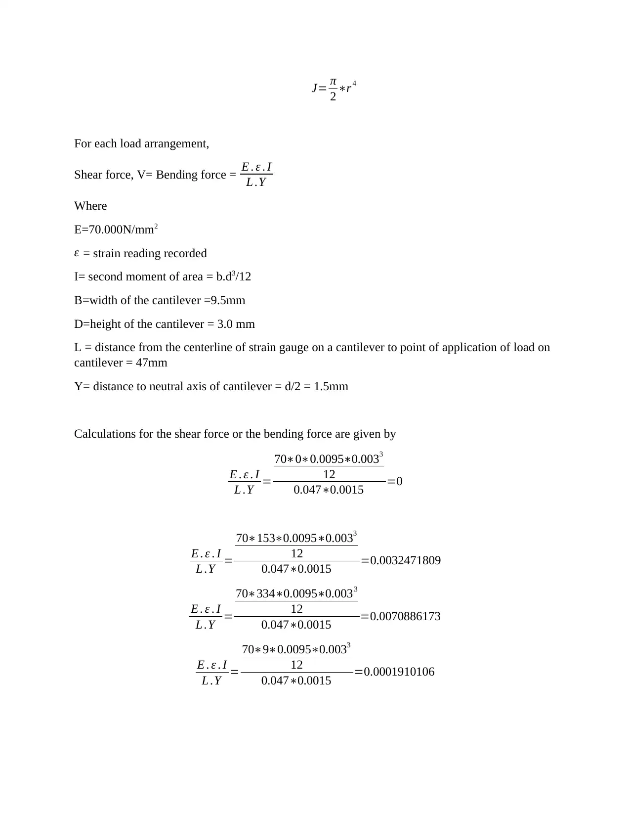
J= π
2 ∗r 4
For each load arrangement,
Shear force, V= Bending force = E . ε . I
L .Y
Where
E=70.000N/mm2
ε = strain reading recorded
I= second moment of area = b.d3/12
B=width of the cantilever =9.5mm
D=height of the cantilever = 3.0 mm
L = distance from the centerline of strain gauge on a cantilever to point of application of load on
cantilever = 47mm
Y= distance to neutral axis of cantilever = d/2 = 1.5mm
Calculations for the shear force or the bending force are given by
E . ε . I
L .Y =
70∗0∗0.0095∗0.0033
12
0.047∗0.0015 =0
E . ε . I
L .Y =
70∗153∗0.0095∗0.0033
12
0.047∗0.0015 =0.0032471809
E . ε . I
L .Y =
70∗334∗0.0095∗0.0033
12
0.047∗0.0015 =0.0070886173
E . ε . I
L .Y =
70∗9∗0.0095∗0.0033
12
0.047∗0.0015 =0.0001910106
⊘ This is a preview!⊘
Do you want full access?
Subscribe today to unlock all pages.

Trusted by 1+ million students worldwide
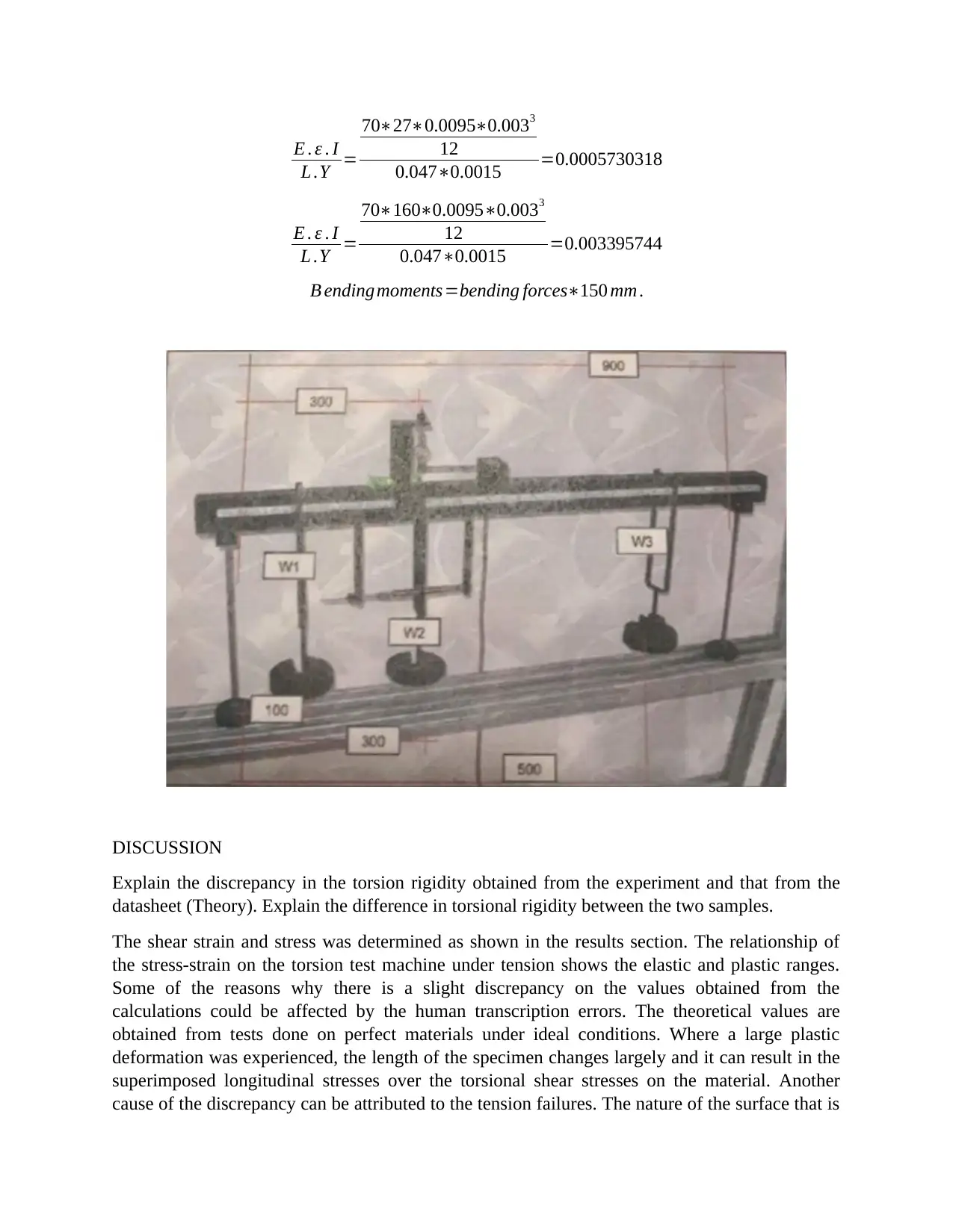
E . ε . I
L .Y =
70∗27∗0.0095∗0.0033
12
0.047∗0.0015 =0.0005730318
E . ε . I
L .Y =
70∗160∗0.0095∗0.0033
12
0.047∗0.0015 =0.003395744
B ending moments=bending forces∗150 mm .
DISCUSSION
Explain the discrepancy in the torsion rigidity obtained from the experiment and that from the
datasheet (Theory). Explain the difference in torsional rigidity between the two samples.
The shear strain and stress was determined as shown in the results section. The relationship of
the stress-strain on the torsion test machine under tension shows the elastic and plastic ranges.
Some of the reasons why there is a slight discrepancy on the values obtained from the
calculations could be affected by the human transcription errors. The theoretical values are
obtained from tests done on perfect materials under ideal conditions. Where a large plastic
deformation was experienced, the length of the specimen changes largely and it can result in the
superimposed longitudinal stresses over the torsional shear stresses on the material. Another
cause of the discrepancy can be attributed to the tension failures. The nature of the surface that is
L .Y =
70∗27∗0.0095∗0.0033
12
0.047∗0.0015 =0.0005730318
E . ε . I
L .Y =
70∗160∗0.0095∗0.0033
12
0.047∗0.0015 =0.003395744
B ending moments=bending forces∗150 mm .
DISCUSSION
Explain the discrepancy in the torsion rigidity obtained from the experiment and that from the
datasheet (Theory). Explain the difference in torsional rigidity between the two samples.
The shear strain and stress was determined as shown in the results section. The relationship of
the stress-strain on the torsion test machine under tension shows the elastic and plastic ranges.
Some of the reasons why there is a slight discrepancy on the values obtained from the
calculations could be affected by the human transcription errors. The theoretical values are
obtained from tests done on perfect materials under ideal conditions. Where a large plastic
deformation was experienced, the length of the specimen changes largely and it can result in the
superimposed longitudinal stresses over the torsional shear stresses on the material. Another
cause of the discrepancy can be attributed to the tension failures. The nature of the surface that is
Paraphrase This Document
Need a fresh take? Get an instant paraphrase of this document with our AI Paraphraser
fractured is proportional to the state of stress in a particular point on the surface of the bar such
that there are ductile failure and brittle failure.
CONCLUSION
In a nutshell, the torsion test is a test done to analyze different factors on a material.
Unfortunately, the torsion test is not a universal test as it does not have consistent testing
procedure, the implication lies on particular mechanical applications for the training on the
elastic materials. The tests are appropriate for testing brittle materials such as tool steels and the
test has also been cast-off to determine the torsion testing levels. The torsion rigidity was tested
using the common torsion equation and the discrepancy of the calculated and theoretical torsion
rigidity was discussed.
REFERENCES
www.doitpoms.ac.uk
SM1/2 Torsion testing machine, TecQuipment Ltd 2000.
Dieter, G.E., Mechanical metallurgy, 1988, SI metric edition, McGraw-Hill, ISBN 0-07-
100406-8.
1 out of 8
Related Documents
Your All-in-One AI-Powered Toolkit for Academic Success.
+13062052269
info@desklib.com
Available 24*7 on WhatsApp / Email
![[object Object]](/_next/static/media/star-bottom.7253800d.svg)
Unlock your academic potential
Copyright © 2020–2026 A2Z Services. All Rights Reserved. Developed and managed by ZUCOL.


