Report on Footings, Wall Panels & Termite Protection Project
VerifiedAdded on 2023/06/15
|11
|2259
|328
Report
AI Summary
This assignment provides a detailed report on various aspects of building and construction, focusing on two projects: a factory complex (Project 3) and a medium-rise apartment building (Project 2). For Project 3, the report discusses the types of footings used, including strip footings, pad footings, and piers, outlining their construction methods, required equipment, and the precise placement of steel columns. It also details a suitable method for the temporary support of concrete wall panels during erection and their connection to the footing. Furthermore, the report addresses the necessity of termite protection for Project 2, referencing the Building Code of Australia and AS 3660, and suggests preventive measures such as minimizing construction joints, protecting service penetrations, using termite-resistant materials, and conducting periodic building inspections. The document concludes with a list of references used in compiling the report.
BUILDING AND CONSTRUCTION ASSIGNMENT
ASSESSMENT 8
2/24/2018
Sat Wason
ASSESSMENT 8
2/24/2018
Sat Wason
Paraphrase This Document
Need a fresh take? Get an instant paraphrase of this document with our AI Paraphraser
Table of Contents
Introduction......................................................................................................................................1
Heading 1: Prepare a brief report on the footings detailed on the plans for Project 3 (factory
complex)..........................................................................................................................................1
Heading 2: Describe the type of footings that are detailed on the plans.....................................2
Heading 2: Outline the construction method and sequence to construct these footings.............2
Heading 2: Include a description of the type of plant and equipment necessary to construct the
footings........................................................................................................................................3
Heading 2: methods used for the placement of steel columns onto footings ensuring that
placement and verticality are precise...........................................................................................4
Heading 1: outline suitable method for the temporary support of the concrete wall panels (for
Project 3) during their erection, and their connection to the footing...............................................6
Heading 1Comment on the need for termite protection for the building in Project 2 (medium rise
apartments), making reference to the Building Code of Australia..................................................8
References......................................................................................................................................10
Introduction
This assignment tackles information about project 3 which is a proposed factory complex located
on 7 Layland way, Banksia and project 2 located which is a medium rise apartment building
located on 2135 The Boulevard, Strathfield.
Heading 1: Prepare a brief report on the footings detailed on the plans
for Project 3 (factory complex).
The footings detailed in the plans for project 3 are strip footing foundation, pad footings and
piers.
Heading 2: Describe the type of footings that are detailed on the plans.
Strip footing foundation – the continuous (strip) footing foundations are a type of shallow
foundations that are used in load bearing walls. They can either be level or stepped. In project 3,
there are four types of strip footings as indicated by the notation SF1, SF2, SF3 and SF4.
The width of the footings are 600mm for SF1, SF2 and SF3. The width for SF4 is 400mm and a
thickness of 450mm at every section except in areas where it is stepped from one level to
another. In such sections the thickness is 850mm with an overlapping distance of 790mm. The
reinforcement in such areas is 2N16 Z-bars as shown in drawing number 1262R/2 Page 26 of 31.
At various intervals of the strip footing foundation, we have pad footings.
Pad footing – The pad footings are used to carry concentrated load from columns. Project 3 has
four types of pad footing foundations. The pads are 1200x1200mm square bases with a thickness
of 600mm. The reinforcement details are shown in drawing number 1262R/2 from page 24 to 27.
The pad footings are then connected to piers that transfer the load carried by the structure further
downwards.
Piers – The project 3 uses 2 types of piers. 450mm diameter piers are used to support the strip
footing foundation and to stiffen the clay strata. 750mm diameter piers are used beneath the pad
footings. The 450mm diameter piers have a reinforcement of 6N16 bars with N12 ties at 240mm
⊘ This is a preview!⊘
Do you want full access?
Subscribe today to unlock all pages.

Trusted by 1+ million students worldwide
centres while the 750mm diameter piers have a reinforcement of 8N16 bars with N10 ties at
250mm centres.1
Heading 2: Outline the construction method and sequence to construct these
footings.
Pier construction – the excavated portions where the piers are located are fixed with the
required reinforcement cage as specified in the structural drawings. A starter of 250mm thickness
is provided so as to act as a base for shuttering. The shuttering involves placing of the necessary
bracing in order for the pier to receive concrete. Concreting is done via a fully automated
operating pump with boom pressure. The concrete grade is M40 and it is after curing for the
required period that the pad footings are concreted into the pier caps. The surface of the pier caps
that are in contact with the pad footing are left rough in readiness to receive concrete of the pad
footings. Backfilling and compaction is done on the sides of the pier up to the level where the
pad footing is to be concreted.
Pad footing foundation – The reinforcement cage of the pad footing is then laid on top of the
pier cap. The formwork shuttering of the pad footings is done in readiness to receive concrete.
The surface of the pier cap which was left rough is watered before the placing of concrete to
ensure a monolithic at the end of the day between the pier cap and the pad footing. The pad
footing is cured according to the requirements of the project and then the strip footing is
concreted as explained.
Strip footing foundation – excavation strips along which the strip footing is to be concreted are
done to the required level. The ground is adequately compacted to the specifications of the
project (98% compaction). The reinforcement of the strip footing is laid and the formwork
shuttering is done in readiness to receive concrete. The ground is sprayed with water so as to
prepare it to receive the concrete. Concreting is done and the formwork shuttering removed after
one day elapses. The footings are adequately cured for a specific period of time before the
ground is backfilled and walling commenced.2
1 Principles of geotechnical engineering by Das M. Braja and Sobhan Khaled date of publication
2013.
2 Foundation design: principles and practices by Donald P Coduto, Published by Pearson
publishers in 2015.
Paraphrase This Document
Need a fresh take? Get an instant paraphrase of this document with our AI Paraphraser
Heading 2: Include a description of the type of plant and equipment necessary
to construct the footings.
Concrete mixer – This is a mechanical equipment that is used in production of a homogeneous
combination of cement, sand, gravel and water to form a concrete paste. The mixers can either be
self-loading transit mixers or hand fed mixers. They help in the delivery of ready to pour
concrete to the footings. The batching ratios are controlled by the strength class of concrete
specified for the project.
Concrete pumps – This equipment is used to transfer liquid concrete to the place where it is
required by pumping. This is the most efficient method of placing concrete in not so easily
accessible areas such as the piers.
Poker vibrators – This equipment is used to ensure that the concrete that is placed is compacted
and that no air is entrained in the concrete that could compromise on its strength. Compaction is
carried out concurrently as concrete is poured in layers.
Slump cone and cube moulds – as the concreting is done, workability tests need to be carried
out to ensure that the consistency of the concrete is to required specifications. The workability
test is carried out on fresh concrete. The compressive strength of concrete is also measured using
the cube moulds which will have to be tested after specific periods of curing. The compressive
strength test is carried out on hardened concrete.
Float blades – This can either be a hand-held tool or a power trowel that is used to smoothen the
surfaces of fresh concrete. They are used to ensure that the finishing of concrete works is up to
the required standard since they produce different finishes on concrete surfaces.
Heading 2: methods used for the placement of steel columns onto footings
ensuring that placement and verticality are precise.
The method used in the placement of the steel columns involves the exact placing of the anchor
bolts. The anchor bolts will be used to make sure the steel columns are located exactly as
specified in the drawings.3
3 Fundamentals of geotechnical engineering by Braja M Das and Nagaratnam Sivakugan,
Cengage Learning 2016.
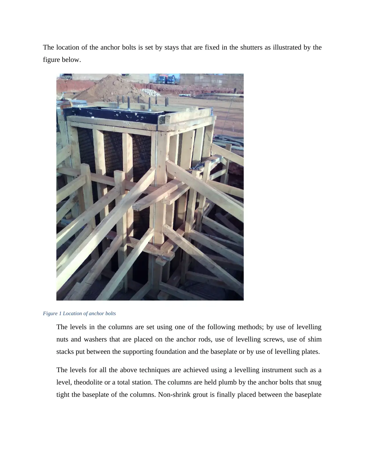
The location of the anchor bolts is set by stays that are fixed in the shutters as illustrated by the
figure below.
Figure 1 Location of anchor bolts
The levels in the columns are set using one of the following methods; by use of levelling
nuts and washers that are placed on the anchor rods, use of levelling screws, use of shim
stacks put between the supporting foundation and the baseplate or by use of levelling plates.
The levels for all the above techniques are achieved using a levelling instrument such as a
level, theodolite or a total station. The columns are held plumb by the anchor bolts that snug
tight the baseplate of the columns. Non-shrink grout is finally placed between the baseplate
⊘ This is a preview!⊘
Do you want full access?
Subscribe today to unlock all pages.

Trusted by 1+ million students worldwide
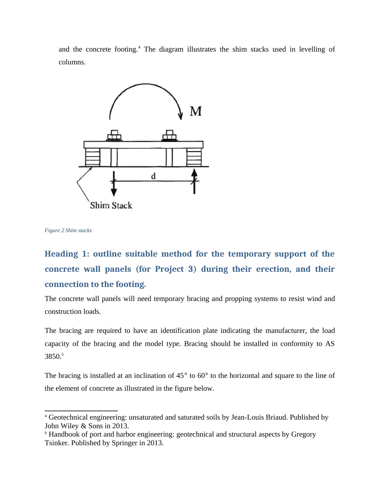
and the concrete footing.4 The diagram illustrates the shim stacks used in levelling of
columns.
Figure 2 Shim stacks
Heading 1: outline suitable method for the temporary support of the
concrete wall panels (for Project 3) during their erection, and their
connection to the footing.
The concrete wall panels will need temporary bracing and propping systems to resist wind and
construction loads.
The bracing are required to have an identification plate indicating the manufacturer, the load
capacity of the bracing and the model type. Bracing should be installed in conformity to AS
3850.5
The bracing is installed at an inclination of 45 ° to 60 ° to the horizontal and square to the line of
the element of concrete as illustrated in the figure below.
4 Geotechnical engineering: unsaturated and saturated soils by Jean-Louis Briaud. Published by
John Wiley & Sons in 2013.
5 Handbook of port and harbor engineering: geotechnical and structural aspects by Gregory
Tsinker. Published by Springer in 2013.
Paraphrase This Document
Need a fresh take? Get an instant paraphrase of this document with our AI Paraphraser
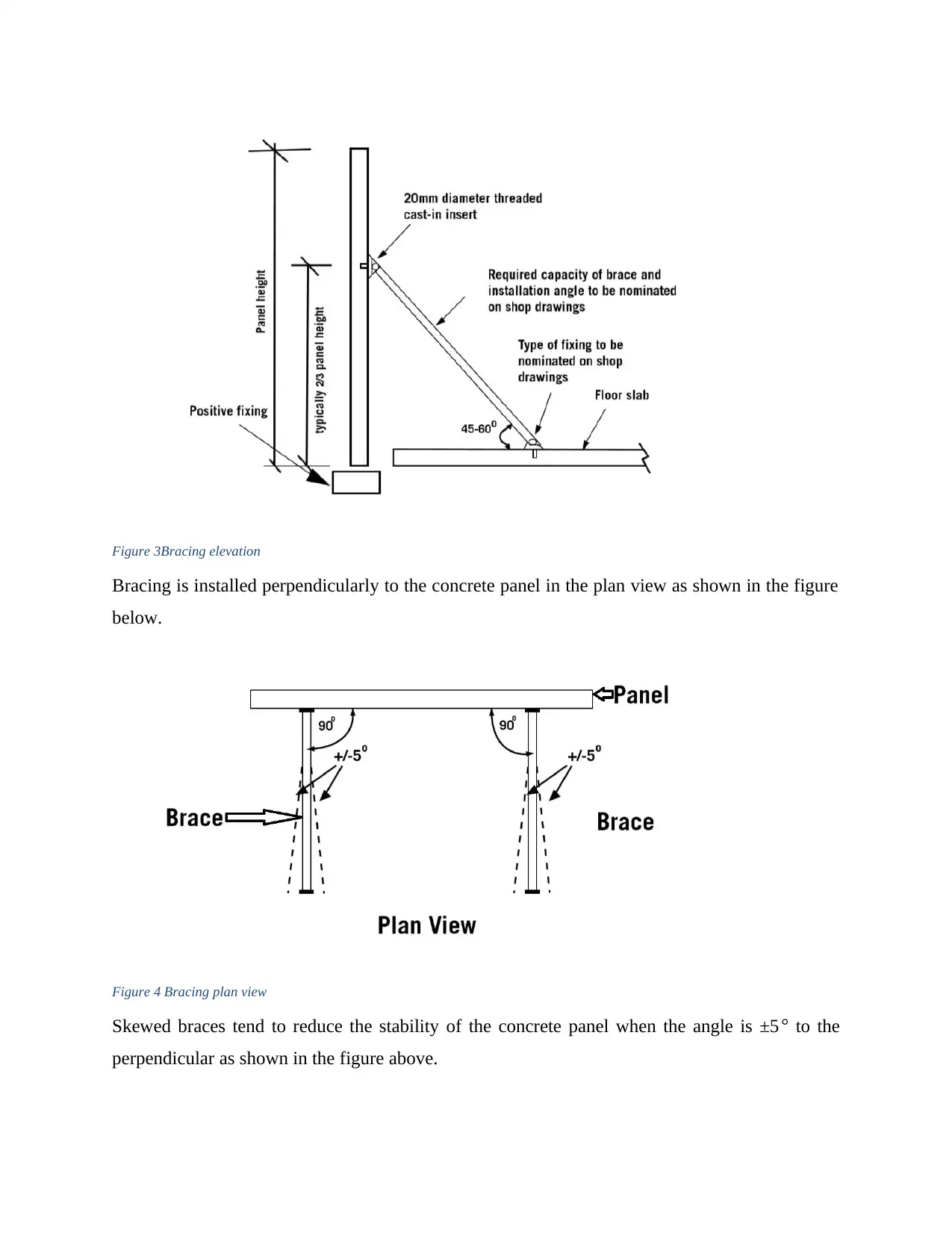
Figure 3Bracing elevation
Bracing is installed perpendicularly to the concrete panel in the plan view as shown in the figure
below.
Figure 4 Bracing plan view
Skewed braces tend to reduce the stability of the concrete panel when the angle is ±5° to the
perpendicular as shown in the figure above.
Bracing is installed perpendicularly to the concrete panel in the plan view as shown in the figure
below.
Figure 4 Bracing plan view
Skewed braces tend to reduce the stability of the concrete panel when the angle is ±5° to the
perpendicular as shown in the figure above.
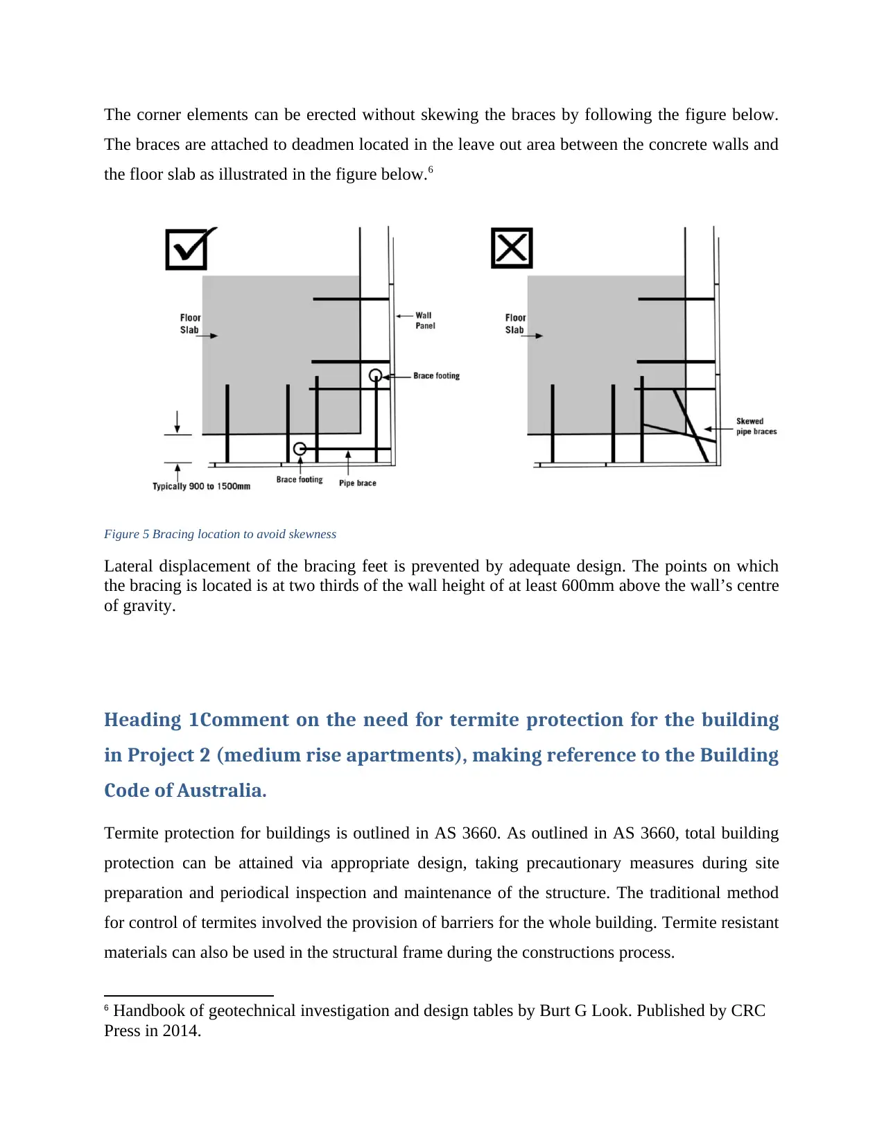
The corner elements can be erected without skewing the braces by following the figure below.
The braces are attached to deadmen located in the leave out area between the concrete walls and
the floor slab as illustrated in the figure below.6
Figure 5 Bracing location to avoid skewness
Lateral displacement of the bracing feet is prevented by adequate design. The points on which
the bracing is located is at two thirds of the wall height of at least 600mm above the wall’s centre
of gravity.
Heading 1Comment on the need for termite protection for the building
in Project 2 (medium rise apartments), making reference to the Building
Code of Australia.
Termite protection for buildings is outlined in AS 3660. As outlined in AS 3660, total building
protection can be attained via appropriate design, taking precautionary measures during site
preparation and periodical inspection and maintenance of the structure. The traditional method
for control of termites involved the provision of barriers for the whole building. Termite resistant
materials can also be used in the structural frame during the constructions process.
6 Handbook of geotechnical investigation and design tables by Burt G Look. Published by CRC
Press in 2014.
⊘ This is a preview!⊘
Do you want full access?
Subscribe today to unlock all pages.

Trusted by 1+ million students worldwide
In project 3, the strip footings and slabs should be designed as integral parts of the structure. The
following precautions need to be taken
Minimizing the number of construction joints. These points serve as the entry points of termites.
Services (plumbing and wiring) should also be designed such that they do not breach through
footings or slabs. In cases where the penetrations are unavoidable, the services are chemically
protected to prevent termite entry.
Use of hollow masonry below ground should also be avoided.
Upon completion of the project, all debris should be cleared from site especially those next to the
subfloor space.
All materials in contact with the ground must be termite resistant.
The strip footings are to be protected by use of barriers such as chemical barriers or the
following range of physical barriers that is Stainless steel mesh or Crushed granite.
Periodic building inspections
The structure should be inspected for all the potential entry points of termites
The installed barriers should be inspected for any signs of breaching by termites.7
7 Foundation engineering handbook by Hsai-Yang Fang. Published by Springer Science &
Business Media in 2013.
Paraphrase This Document
Need a fresh take? Get an instant paraphrase of this document with our AI Paraphraser
References
Principles of geotechnical engineering by Das M. Braja and Sobhan Khaled date of publication
2013.
2 Foundation design: principles and practices by Donald P Coduto, Published by Pearson
publishers in 2015.
3 Fundamentals of geotechnical engineering by Braja M Das and Nagaratnam Sivakugan,
Cengage Learning 2016.
4 Geotechnical engineering: unsaturated and saturated soils by Jean-Louis Briaud. Published by
John Wiley & Sons in 2013.
5 Handbook of port and harbor engineering: geotechnical and structural aspects by Gregory
Tsinker. Published by Springer in 2013.
6 Handbook of port and harbor engineering: geotechnical and structural aspects by Gregory
Tsinker. Published by Springer in 2013.
7 Foundation engineering handbook by Hsai-Yang Fang. Published by Springer Science &
Business Media in 2013.
1 out of 11
Related Documents
Your All-in-One AI-Powered Toolkit for Academic Success.
+13062052269
info@desklib.com
Available 24*7 on WhatsApp / Email
![[object Object]](/_next/static/media/star-bottom.7253800d.svg)
Unlock your academic potential
Copyright © 2020–2026 A2Z Services. All Rights Reserved. Developed and managed by ZUCOL.


