Project Information - Assignment PDF
VerifiedAdded on 2021/05/31
|8
|1659
|146
AI Summary
Contribute Materials
Your contribution can guide someone’s learning journey. Share your
documents today.
CE 2.1 Project Information
Name of the project: Design and Fabrication of Wireless Power Transfer System
Location of the project: Please fill
Project Duration: Please fill
Organization: Please fill
Role and Designation during the time: Team Member of the project
CE 2.2 Project Background
CE 2.2.1 Characteristics of the project
The project of Design and Fabrication of Wireless Power Transfer System was the
second significant project in my engineering and professional career. The concept of the wireless
power transfer eventually refers to the proper transmission of the electrical power from any
source to the consuming device by not utilizing the wired conductors. Moreover, this project has
also focused on the latest technology for the wireless power transfer that would be providing on
the longer range of electrical power transfer in the wireless mode. The range in which power is
transferred successfully was found to be more than 2m for LED bulb and 2m for small motor
driven fan as a load.
CE 2.2.2 Objectives developed for the project
This project of Design and Fabrication of Wireless Power Transfer System majorly
comprises of several objectives. The most significant objectives in this project are given below:
To develop and fabricate a wireless power transfer system.
Secure Best Marks with AI Grader
Need help grading? Try our AI Grader for instant feedback on your assignments.
To transfer electrical power without any type of wires.
CE 2.2.3 My Area of work
My major area of work was to make the design of wireless electrical power transfer
system. My next work area was to make the project report properly. I had the idea that if this
documentation would not be done properly, it is needless to mention that the remaining project
part would also become a failure. Since, this was my second big project, the team members and
project leader had proactively helped me to understand the project entirely and thus complete the
report part.
CE 2.2.4 Project Group
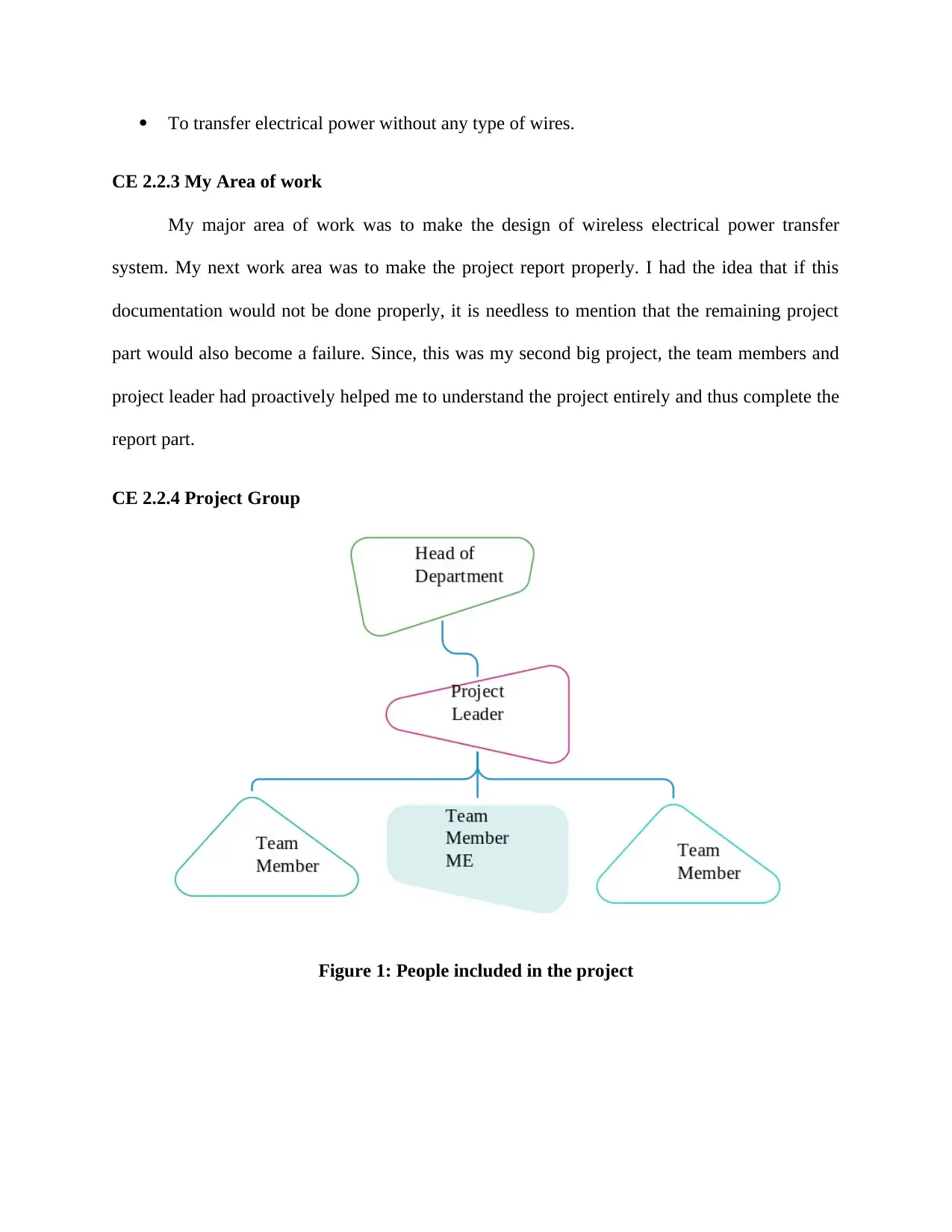
Figure 1: People included in the project
CE 2.2.5 My responsibilities throughout the project
I had various responsibilities in this project. My major responsibility was to make the
project design of our project perfectly. I even documented or noted down the readings of the
project. I made sure that the documentation was made perfectly. My next responsibility was to
arrange daily meetings for our project growth. Moreover, I even made sure that important
workshops are attended in this phenomenon. My other responsibility was to assist my project
leader in the project and make sure that everything was under control.
CE 2.3 Distinctive Activity
CE 2.3.1 Comprehending the Theory of the project
This project of Design and Fabrication of Wireless Power Transfer System was extremely
beneficial for the electrical engineering domain. The advanced wireless power transfer system or
AWEPTS helps in including various technologies to transmit power by not connecting with the
several man made conductors. The most advanced methods of the wireless electrical power
transfer systems mainly include induction, electromagnetic transmission, electro dynamic
induction, radio and microwave, electrostatic induction, transfer of Laser beam and many more.
The principle of the mutual induction within two coils could be easily utilized for electric
power transfer by not involving any physical contact amongst themselves. Induction can easily
work as the transformer, where no physical contact is present within the primary coil ad
secondary coil. Energy transfer is possible for the electromagnetic coupling. Within the
electromagnetic transmission, the conversion of electricity to light like the laser beam for firing
the beam at the receiving target like solar cell on the smaller aircraft. The electro dynamic
induction is the resonant inductive coupling that would be solving the significant problem of
wireless energy transfer. The efficiency of the transmission is checked on the transmission of
distance. The radio and microwave is the simple technique to transmit power in the most
effective way by enabling long distance power beaming with extremely shorter wavelengths of
the electromagnetic radiation within the microwave range. The conversion of rectenna
efficiencies eventually exceeded 95% of the total transmission. The fifth method is the
electrostatic induction. The other name of this method is capacititve coupling. It is the gradient
of electric field or the differential capacitance within the two elevated electrodes over the
conductive ground plane for the transmission of wireless energy. There are various differences
between the two nodes. The last or the final method for wireless data transfer is the laser beam
transfer. Here, the laser is eventually beamed for each and every photovoltaic cell that could
extract the entire electrical energy. Laser method is not at all easy for implementation and
management.
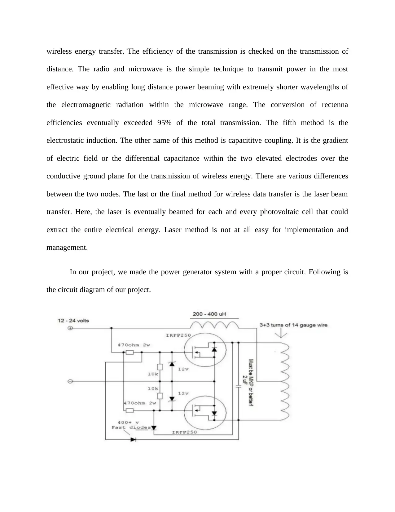
In our project, we made the power generator system with a proper circuit. Following is
the circuit diagram of our project.
Secure Best Marks with AI Grader
Need help grading? Try our AI Grader for instant feedback on your assignments.
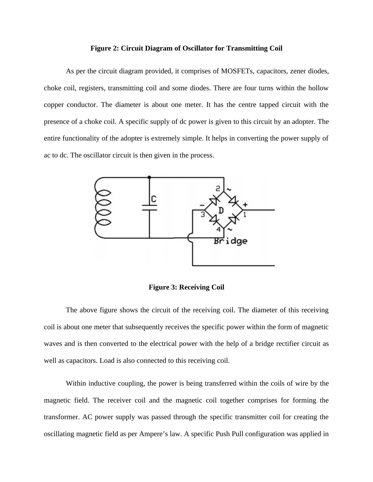
Figure 2: Circuit Diagram of Oscillator for Transmitting Coil
As per the circuit diagram provided, it comprises of MOSFETs, capacitors, zener diodes,
choke coil, registers, transmitting coil and some diodes. There are four turns within the hollow
copper conductor. The diameter is about one meter. It has the centre tapped circuit with the
presence of a choke coil. A specific supply of dc power is given to this circuit by an adopter. The
entire functionality of the adopter is extremely simple. It helps in converting the power supply of
ac to dc. The oscillator circuit is then given in the process.
Figure 3: Receiving Coil
The above figure shows the circuit of the receiving coil. The diameter of this receiving
coil is about one meter that subsequently receives the specific power within the form of magnetic
waves and is then converted to the electrical power with the help of a bridge rectifier circuit as
well as capacitors. Load is also connected to this receiving coil.
Within inductive coupling, the power is being transferred within the coils of wire by the
magnetic field. The receiver coil and the magnetic coil together comprises for forming the
transformer. AC power supply was passed through the specific transmitter coil for creating the
oscillating magnetic field as per Ampere’s law. A specific Push Pull configuration was applied in
this project. This push pull amplifier had the output stage, which could easily drive the current in
any of the direction. This could be done with the help of load present in it. The specific output
stage of this push pull amplifier comprised of two identical MOSFETs. One of them was
sourcing current from the load; on the other hand, the second one was sinking this current from
the load. Harmonics were present within the circuit and after successful filtration of these
harmonics, more power was being transmitted wirelessly and hence our project became
successful.
CE 2.3.2 Engineering Knowledge and Skills applied in the project
I had properly used my excellent skills of electrical for completing this project. I had
knowledge of core electrical engineering, which was eventually required here. Moreover, my
computer proficiencies were also used here for the proper documentation. I had the power of
problem solving and critical thinking and this power helped me face difficult situations in the
project easily.
CE 2.3.4 Identified issues and their solutions
2.3.4.1 Issues
The problem that I faced in this problem was during applying inductive coupling. The
EMF was not being induced properly within the magnetic field and thus our project was getting
delayed. Moreover, the MOSFET that we selected in the first attempt went out completely
wrong and was providing wrong results.
2.3.4.2 Solutions
For this particular problem, I gave the idea if using Faraday’s law of induction. With this
particular idea, the AC current was being created within the receiver. This AC current was then
rectified to DC or direct current with the help of a rectifier present in the specific receiver and
thus DC load was driven. For the second problem, I selected the MOSFET of IRFP250N for our
project. Thus, with the help of my intellect and engineering knowledge, I was able to solve the
two problems and our project was completed in time.
CE 2.3.5 Plan to produce creative and innovative work
We made a proper plan to produce innovative and creative work. At first, we segregated
our jobs and made sure that each and everyone works on the project proactively. Moreover, we
met on regular meetings and thus were able to find out our faults easily.
CE 2.4 Project Review
CE 2.4.1 Project overview
The project of Design and Fabrication of Wireless Power Transfer System mainly
comprised of the image and signal processing. This project was my second major project in
career and helped me to understand and gain experience in practical world. The project
comprised of four members, which included my project leader, me and my team members. The
budget was strictly followed in the project and documentation was made perfectly. The project
was successful with our collaborative work.
CE 2.4.2 My Contribution to the work
I was the most important part in the project. My most significant contribution to the
project was in the documentation part. I researched about the project and suggested the topic to
my team gained knowledge in this field. I even assisted my project leader during the project
Paraphrase This Document
Need a fresh take? Get an instant paraphrase of this document with our AI Paraphraser

tenure and in absence of him; I leaded the team with my leadership skills. I even arranged for
daily meetings after office hours.
daily meetings after office hours.
1 out of 8
Related Documents
Your All-in-One AI-Powered Toolkit for Academic Success.
+13062052269
info@desklib.com
Available 24*7 on WhatsApp / Email
![[object Object]](/_next/static/media/star-bottom.7253800d.svg)
Unlock your academic potential
© 2024 | Zucol Services PVT LTD | All rights reserved.


