3D Geometry of a Carabiner- Design Report
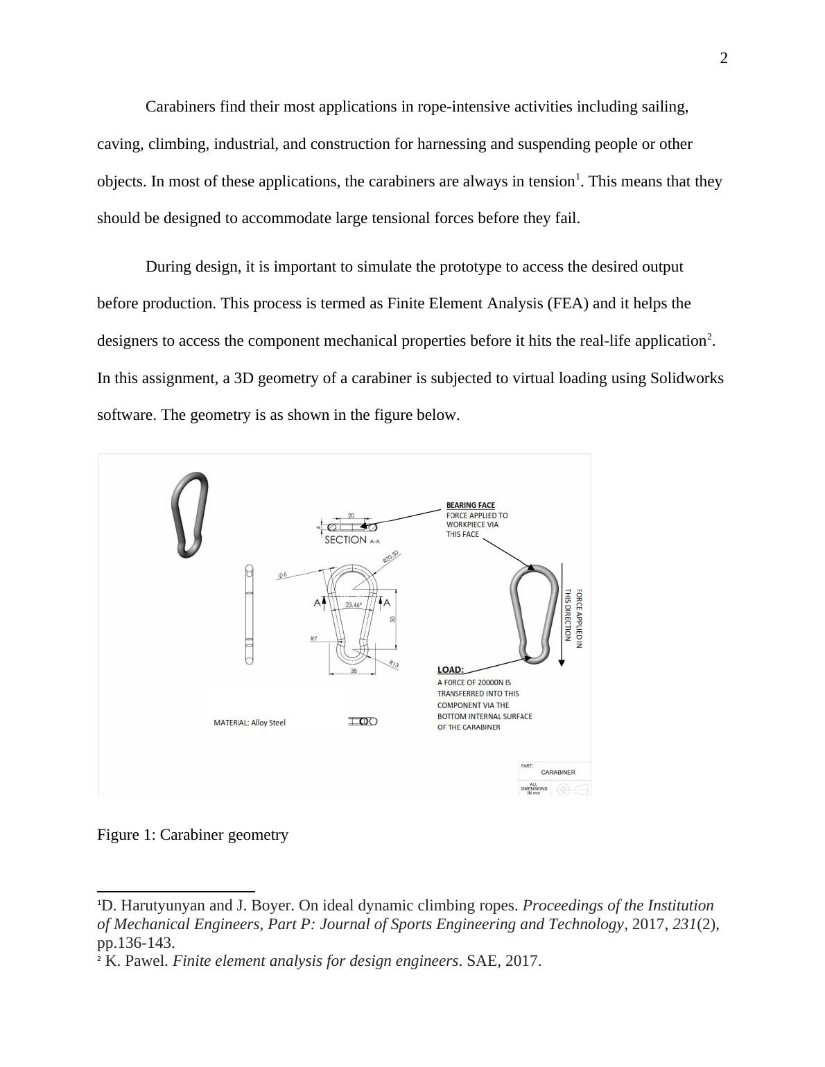
This assignment requires the analysis and design of a carabiner using Finite Element Analysis (FEA) software.
6 Pages724 Words13 Views
Added on 2022-07-28
3D Geometry of a Carabiner- Design Report
This assignment requires the analysis and design of a carabiner using Finite Element Analysis (FEA) software.
Added on 2022-07-28
ShareRelated Documents
End of preview
Want to access all the pages? Upload your documents or become a member.
Finite Element Analysis
|9
|1446
|365
FEA Analysis of Bracket Design: Material Properties and Design Improvements
|6
|1613
|132
Engineering Science Part 1: Materials, Design, and Principles
|10
|2827
|172
Design and FEA Analysis of Connecting Rod for Engine
|50
|4240
|265
Connecting Rod Design and FEA Analysis - Desklib
|56
|4240
|96
Stress Analysis of Bracket
|6
|516
|200