ProductsLogo
LogoStudy Documents
LogoAI Grader
LogoAI Answer
LogoAI Code Checker
LogoPlagiarism Checker
LogoAI Paraphraser
LogoAI Quiz
LogoAI Detector
PricingBlogAbout Us
logo

Computer Organization and Architecture

Verified

Added on  2019/11/12

|5
|401
|222
Report
AI Summary
The assignment content discusses computer organization and architecture, specifically focusing on data representation and digital logic. It provides detailed answers to questions related to IEEE 754 format, signed magnitude, one's complement, and two's complement. Additionally, it describes the construction of a logic circuit using basic gates (AND, OR, NOT) to activate the CSU main entrance door from specific time intervals.

Contribute Materials

Your contribution can guide someone’s learning journey. Share your documents today.
Document Page
Running head: COMPUTER ORGANIZATION AND ARCHITECTURE
Computer Organization and Architecture
Student Name:
Student ID:
Subject Code: ITC544
Assignment 1: Data Representation and Digital Logic
Author’s Note

Secure Best Marks with AI Grader

Need help grading? Try our AI Grader for instant feedback on your assignments.
Document Page
1
COMPUTER ORGANIZATION AND ARCHITECTURE
Answer to Question 1:
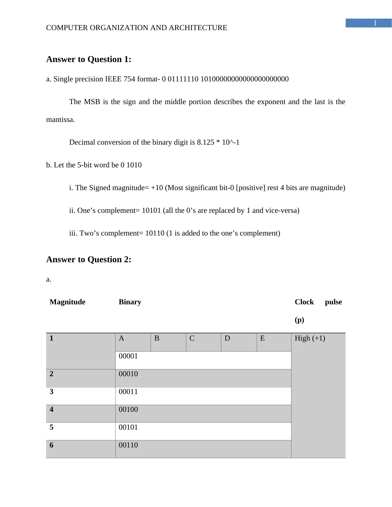
a. Single precision IEEE 754 format- 0 01111110 10100000000000000000000
The MSB is the sign and the middle portion describes the exponent and the last is the
mantissa.
Decimal conversion of the binary digit is 8.125 * 10^-1
b. Let the 5-bit word be 0 1010
i. The Signed magnitude= +10 (Most significant bit-0 [positive] rest 4 bits are magnitude)
ii. One’s complement= 10101 (all the 0’s are replaced by 1 and vice-versa)
iii. Two’s complement= 10110 (1 is added to the one’s complement)
Answer to Question 2:
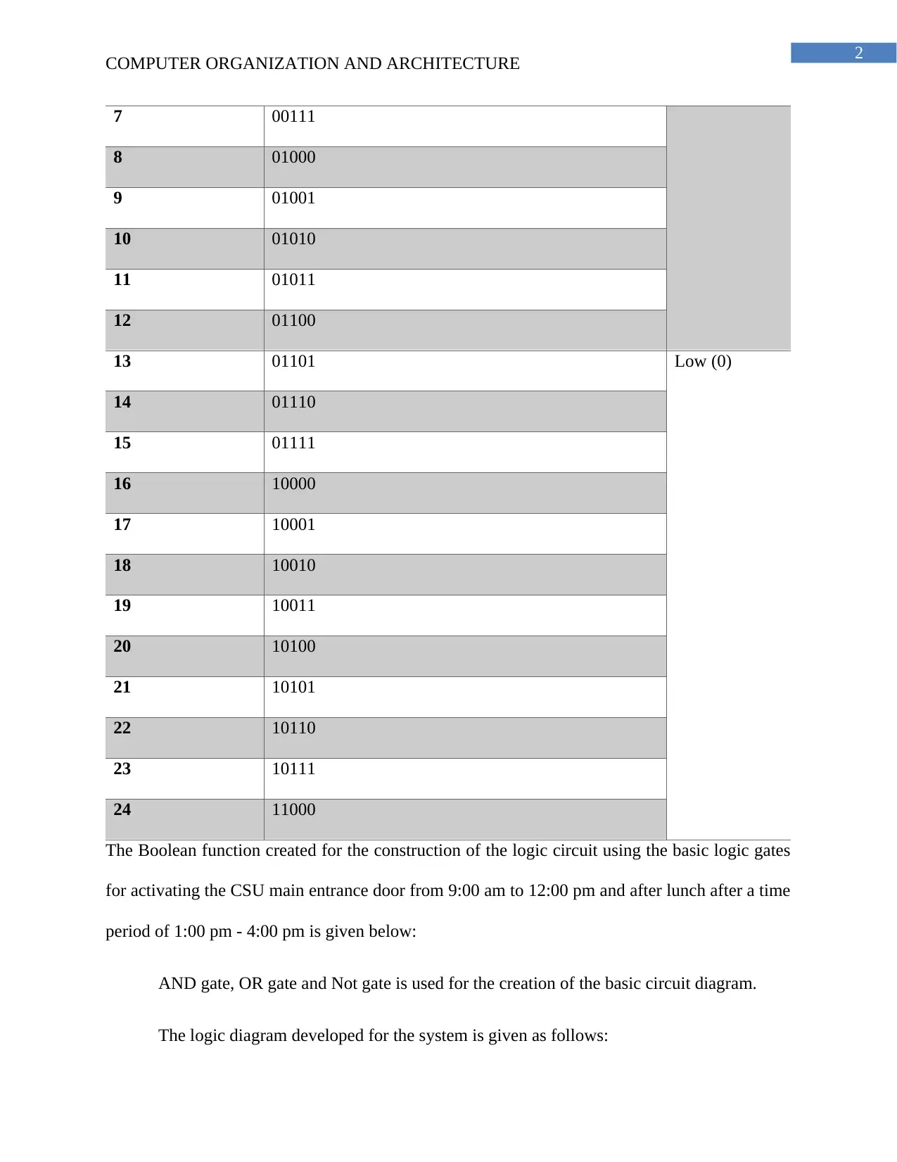
a.
Magnitude Binary Clock pulse
(p)
1 A B C D E High (+1)
00001
2 00010
3 00011
4 00100
5 00101
6 00110
Document Page
2
COMPUTER ORGANIZATION AND ARCHITECTURE
7 00111
8 01000
9 01001
10 01010
11 01011
12 01100
13 01101 Low (0)
14 01110
15 01111
16 10000
17 10001
18 10010
19 10011
20 10100
21 10101
22 10110
23 10111
24 11000
The Boolean function created for the construction of the logic circuit using the basic logic gates
for activating the CSU main entrance door from 9:00 am to 12:00 pm and after lunch after a time
period of 1:00 pm - 4:00 pm is given below:
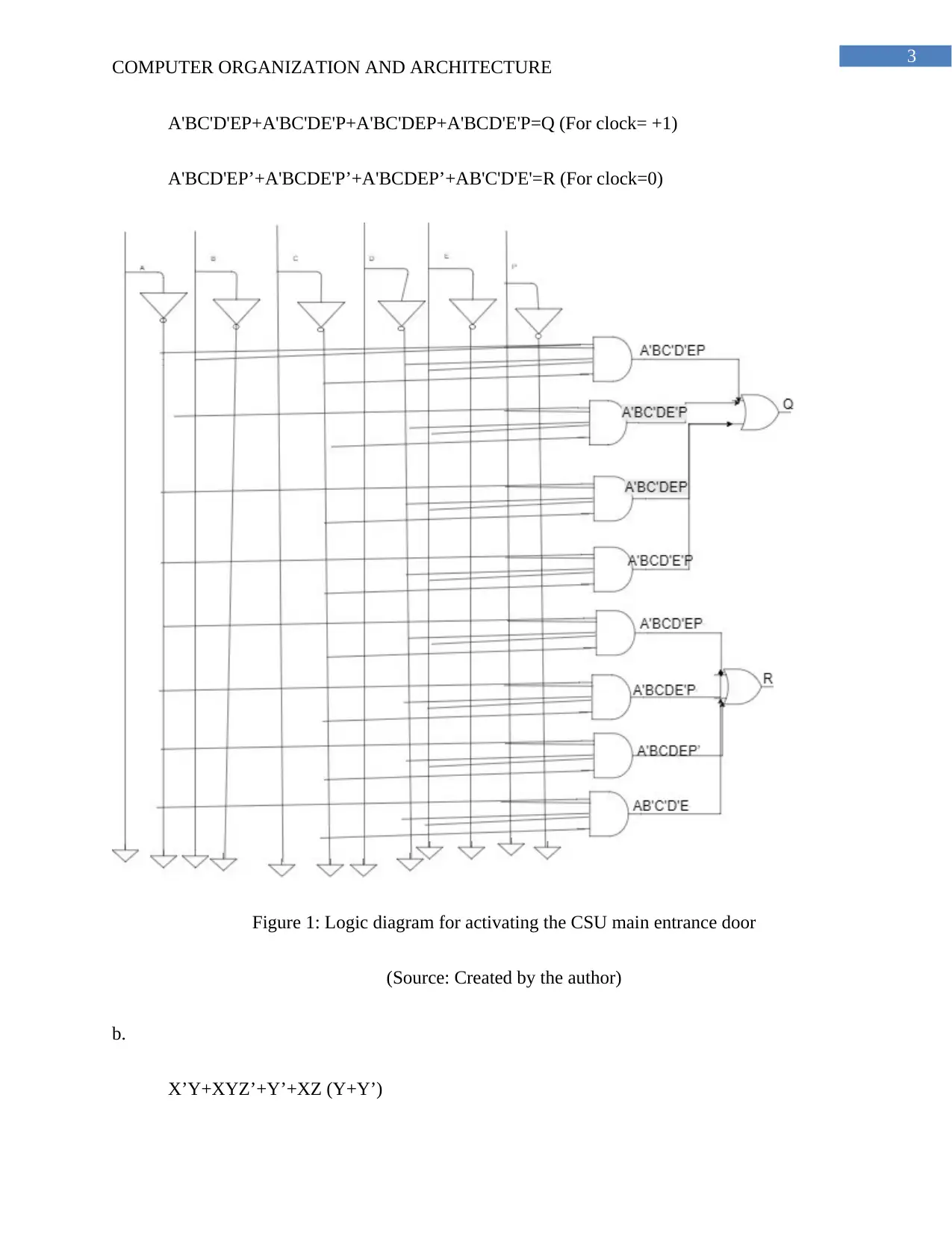
AND gate, OR gate and Not gate is used for the creation of the basic circuit diagram.
The logic diagram developed for the system is given as follows:
Document Page
3
COMPUTER ORGANIZATION AND ARCHITECTURE
A'BC'D'EP+A'BC'DE'P+A'BC'DEP+A'BCD'E'P=Q (For clock= +1)
A'BCD'EP’+A'BCDE'P’+A'BCDEP’+AB'C'D'E'=R (For clock=0)
Figure 1: Logic diagram for activating the CSU main entrance door
(Source: Created by the author)
b.
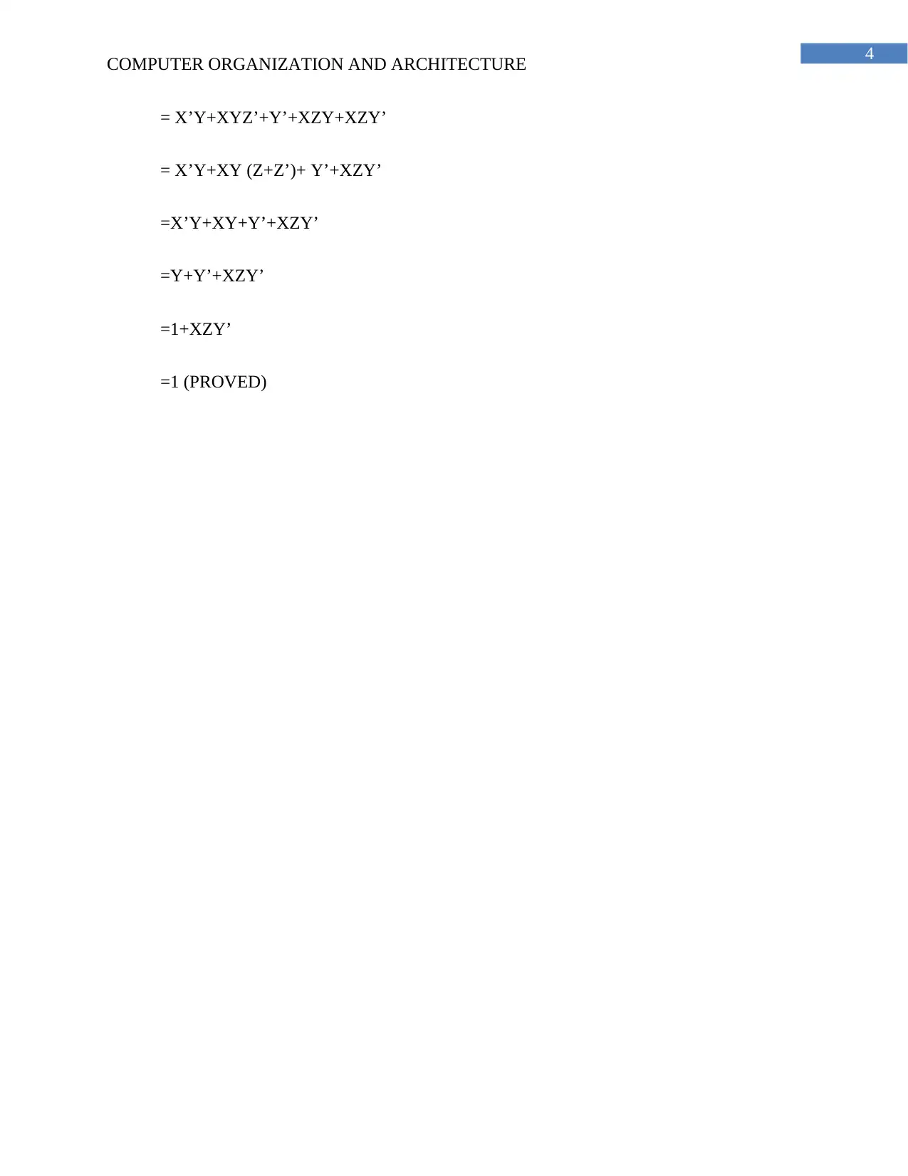
X’Y+XYZ’+Y’+XZ (Y+Y’)

Paraphrase This Document

Need a fresh take? Get an instant paraphrase of this document with our AI Paraphraser
Document Page
4
COMPUTER ORGANIZATION AND ARCHITECTURE
= X’Y+XYZ’+Y’+XZY+XZY’
= X’Y+XY (Z+Z’)+ Y’+XZY’
=X’Y+XY+Y’+XZY’
=Y+Y’+XZY’
=1+XZY’
=1 (PROVED)
1 out of 5
[object Object]

Your All-in-One AI-Powered Toolkit for Academic Success.

Available 24*7 on WhatsApp / Email

[object Object]