logo

Building a Lift Operational Logic Circuit in Logisim

Create a digital logic simulator circuit using Logisim and submit it along with a written report in PDF format.

8 Pages976 Words226 Views
   

Added on  2022-11-26

About This Document

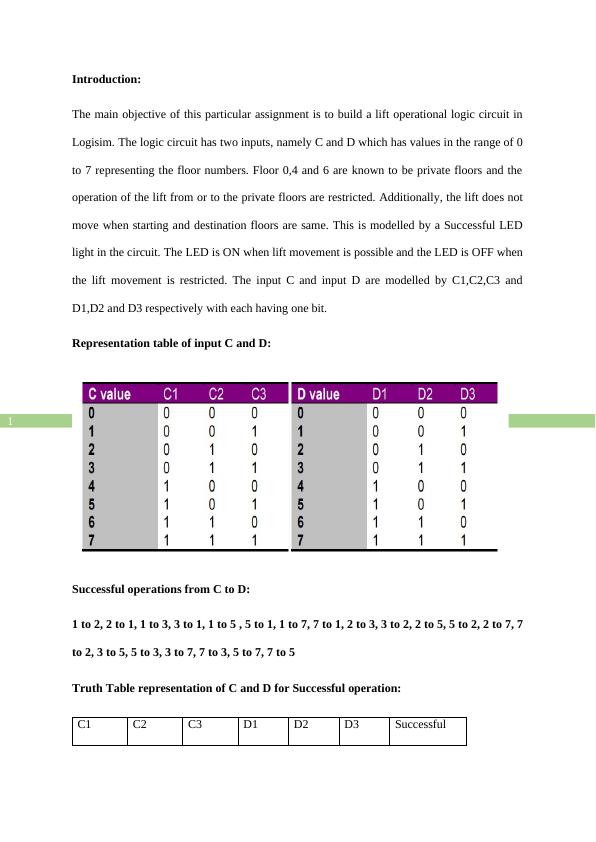
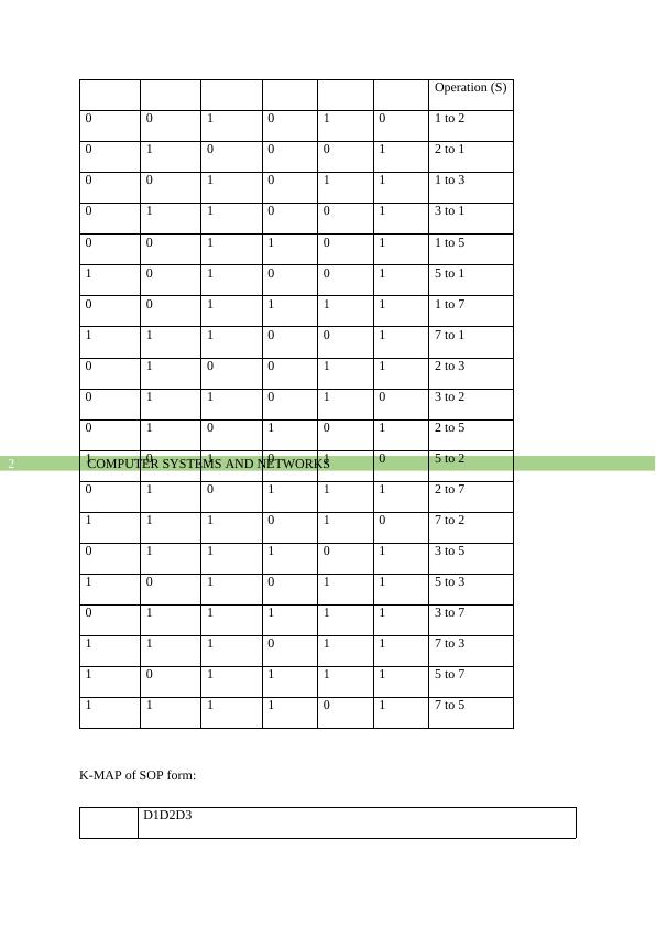
This assignment focuses on building a lift operational logic circuit in Logisim. It covers the inputs, restrictions, and successful operations of the lift.

Building a Lift Operational Logic Circuit in Logisim

Create a digital logic simulator circuit using Logisim and submit it along with a written report in PDF format.

   Added on 2022-11-26

ShareRelated Documents
Running head: COMPUTER SYSTEMS AND NETWORKS
COMPUTER SYSTEMS AND NETWORKS
Name of the Student
Name of the University
Author Note
Building a Lift Operational Logic Circuit in Logisim_1
COMPUTER SYSTEMS AND NETWORKS1
Introduction:
The main objective of this particular assignment is to build a lift operational logic circuit in
Logisim. The logic circuit has two inputs, namely C and D which has values in the range of 0
to 7 representing the floor numbers. Floor 0,4 and 6 are known to be private floors and the
operation of the lift from or to the private floors are restricted. Additionally, the lift does not
move when starting and destination floors are same. This is modelled by a Successful LED
light in the circuit. The LED is ON when lift movement is possible and the LED is OFF when
the lift movement is restricted. The input C and input D are modelled by C1,C2,C3 and
D1,D2 and D3 respectively with each having one bit.
Representation table of input C and D:
Successful operations from C to D:
1 to 2, 2 to 1, 1 to 3, 3 to 1, 1 to 5 , 5 to 1, 1 to 7, 7 to 1, 2 to 3, 3 to 2, 2 to 5, 5 to 2, 2 to 7, 7
to 2, 3 to 5, 5 to 3, 3 to 7, 7 to 3, 5 to 7, 7 to 5
Truth Table representation of C and D for Successful operation:
C1 C2 C3 D1 D2 D3 Successful
Building a Lift Operational Logic Circuit in Logisim_2
COMPUTER SYSTEMS AND NETWORKS2
Operation (S)
0 0 1 0 1 0 1 to 2
0 1 0 0 0 1 2 to 1
0 0 1 0 1 1 1 to 3
0 1 1 0 0 1 3 to 1
0 0 1 1 0 1 1 to 5
1 0 1 0 0 1 5 to 1
0 0 1 1 1 1 1 to 7
1 1 1 0 0 1 7 to 1
0 1 0 0 1 1 2 to 3
0 1 1 0 1 0 3 to 2
0 1 0 1 0 1 2 to 5
1 0 1 0 1 0 5 to 2
0 1 0 1 1 1 2 to 7
1 1 1 0 1 0 7 to 2
0 1 1 1 0 1 3 to 5
1 0 1 0 1 1 5 to 3
0 1 1 1 1 1 3 to 7
1 1 1 0 1 1 7 to 3
1 0 1 1 1 1 5 to 7
1 1 1 1 0 1 7 to 5
K-MAP of SOP form:
D1D2D3
Building a Lift Operational Logic Circuit in Logisim_3

End of preview

Want to access all the pages? Upload your documents or become a member.

Related Documents
Developing a Logisim Circuit for a Lift Simulation System
|8
|1012
|75

Computer Architecture Assignment: Binary Addresses
|2
|305
|134

Design Procedure for Comparator Circuit
|17
|1598
|371

Circuit Function: Decoder and Comparator for Lift Movement
|6
|1194
|63

Wireless Communication
|15
|2137
|296

DIGITAL LOGIC QUESTION ONE 4 BIT ADDER-SUBTRACTOR
|10
|942
|259