1007ICT/7611ICT: Lift Simulation Circuit Design and Implementation
VerifiedAdded on 2023/01/11
|8
|1012
|75
Project
AI Summary
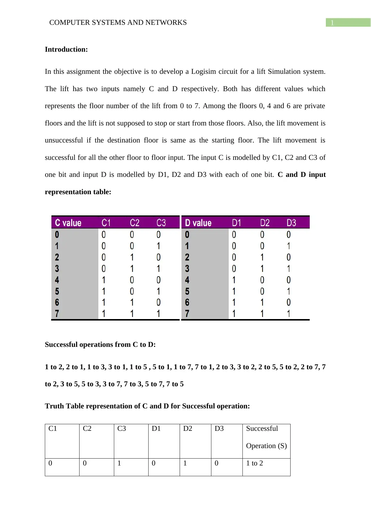
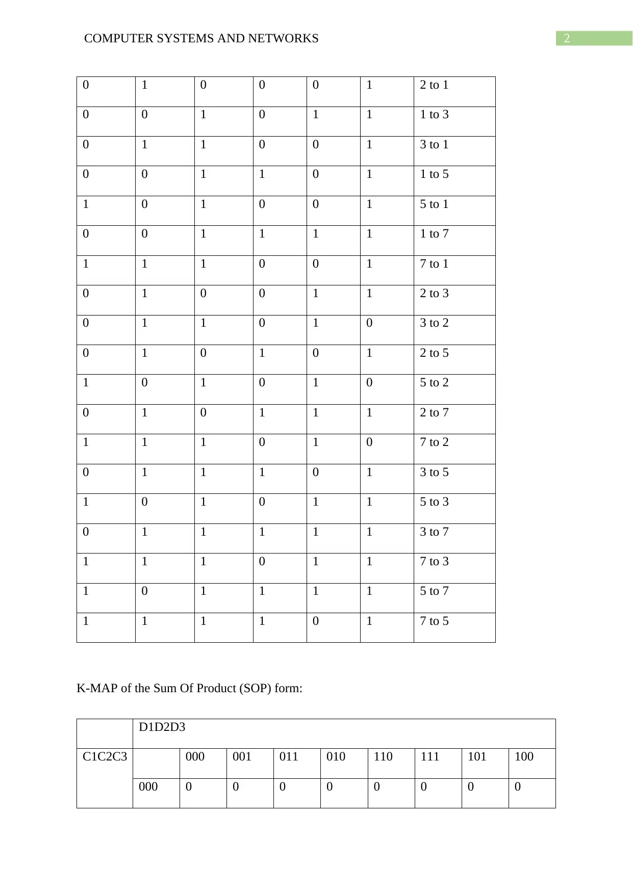
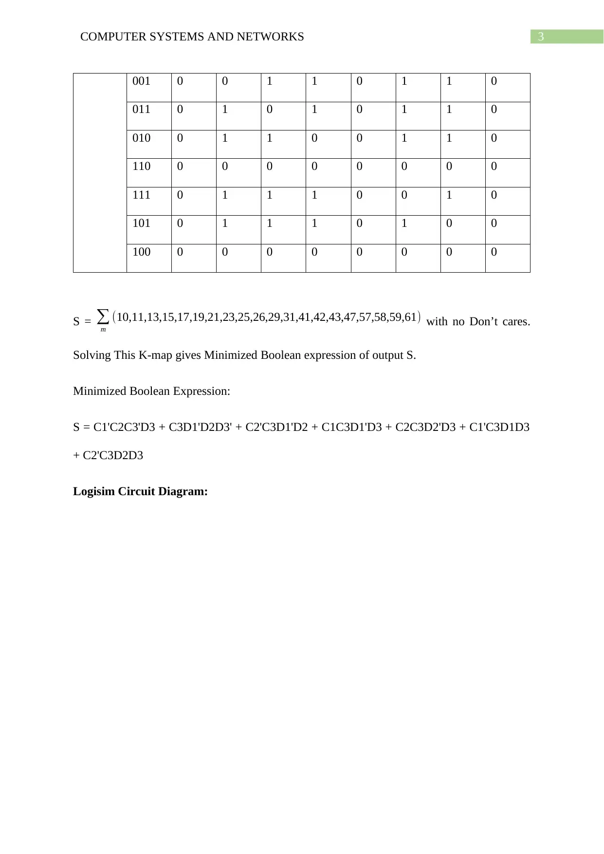
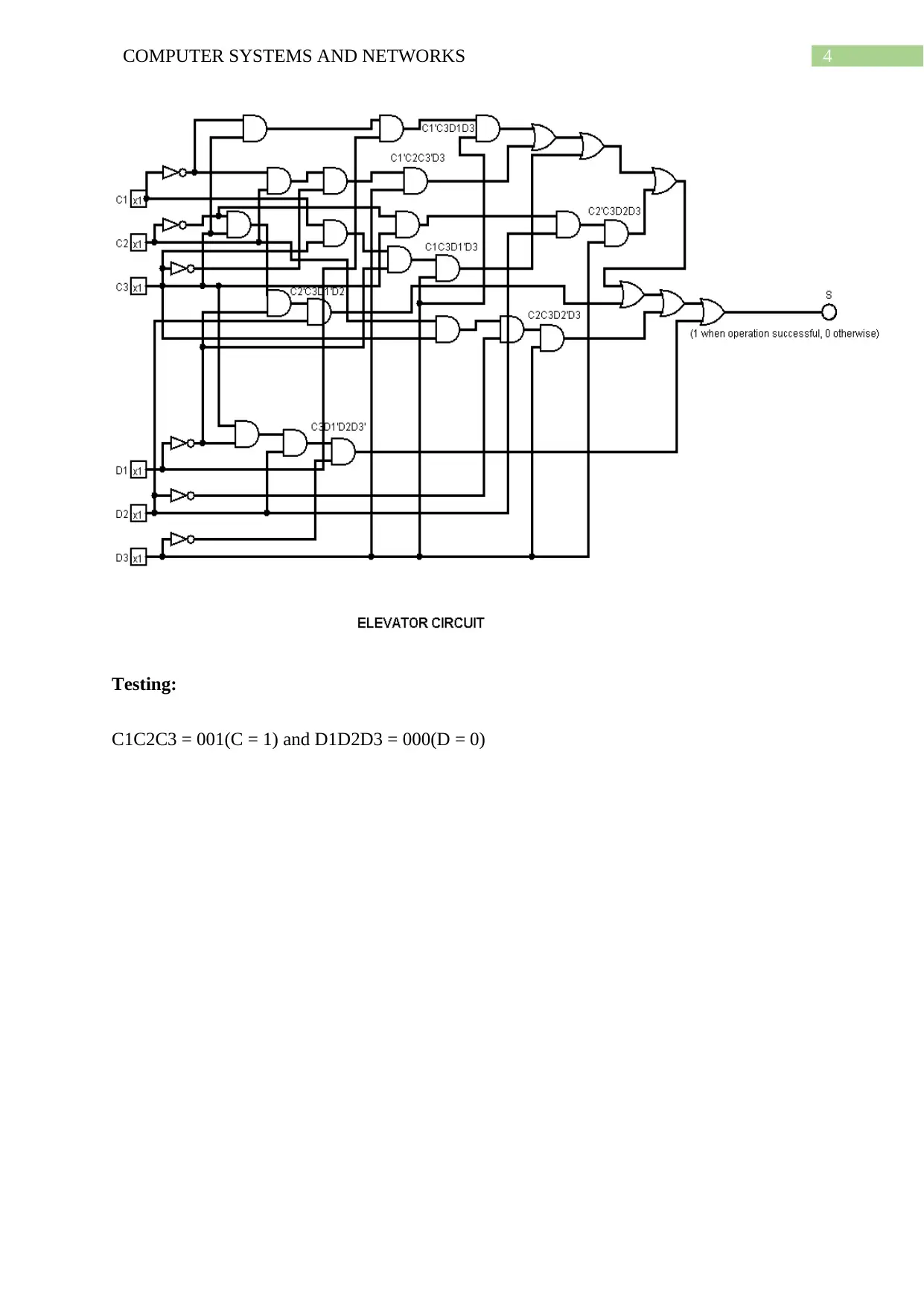
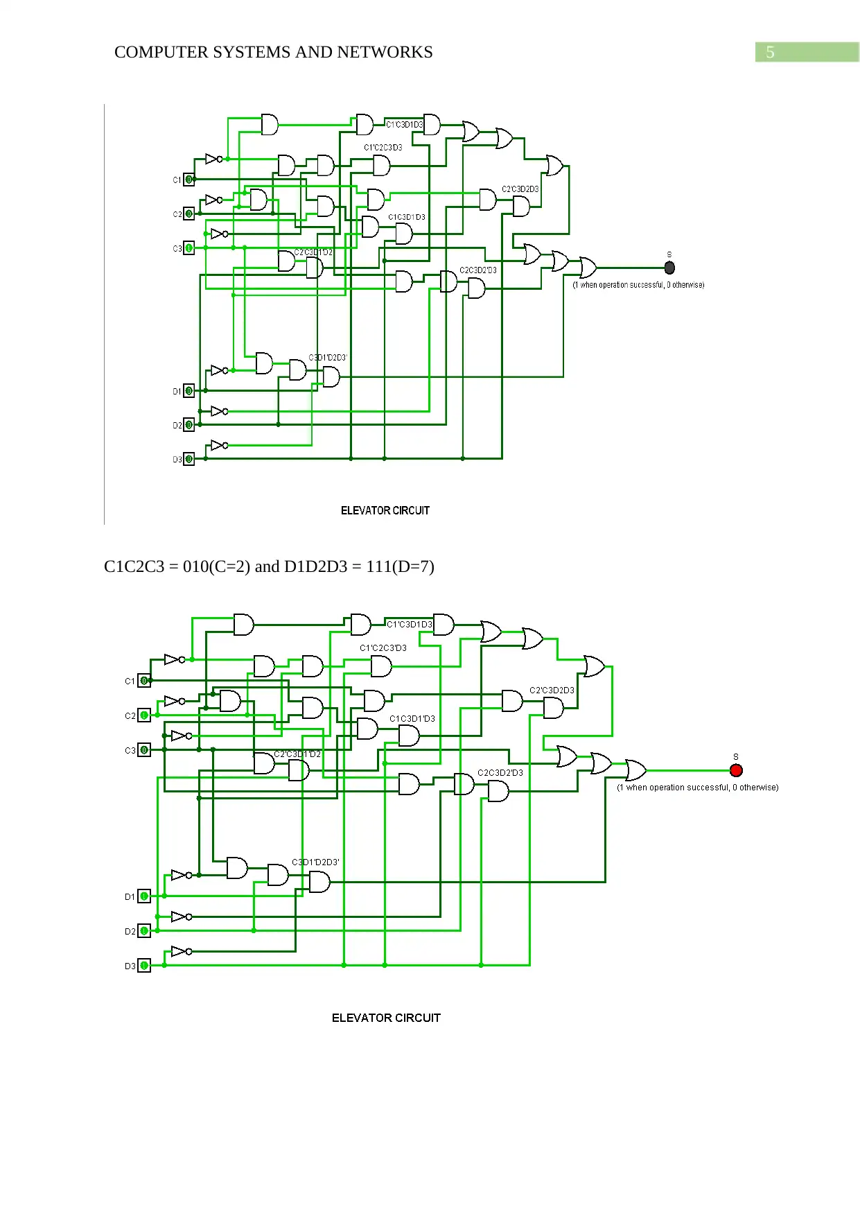
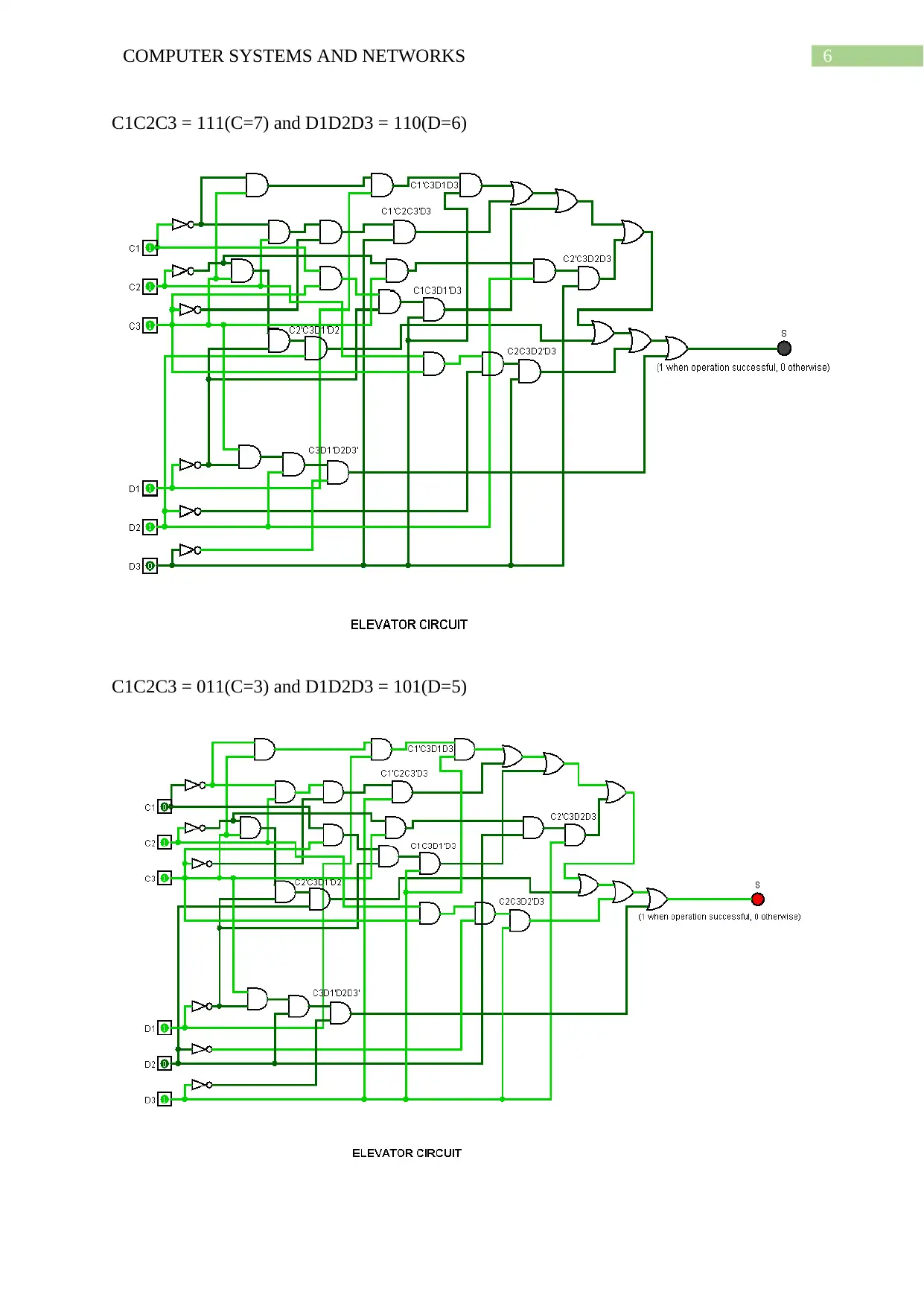
This assignment details the design and implementation of a lift simulation system using Logisim. The system takes inputs representing the lift's current and destination floors (0-7), with floors 0, 4, and 6 designated as private floors where the lift should not stop. The assignment includes a truth table representing successful lift operations, a K-map for minimizing the Boolean expression, and the resulting Logisim circuit diagram. The circuit utilizes basic logic gates (AND, OR, NOT) to determine the successful operation of the lift based on the given conditions. The report also includes testing scenarios to validate the circuit's functionality, demonstrating the lift's behavior based on the input values and rules. The conclusion summarizes the successful implementation of the lift simulation and suggests potential future enhancements to the design.
1 out of 8
Related Documents


Your All-in-One AI-Powered Toolkit for Academic Success.
+13062052269
info@desklib.com
Available 24*7 on WhatsApp / Email
![[object Object]](/_next/static/media/star-bottom.7253800d.svg)
Copyright © 2020–2026 A2Z Services. All Rights Reserved. Developed and managed by ZUCOL.