Comprehensive Report: Construction Information Production & Analysis
VerifiedAdded on 2023/06/03
|19
|4525
|193
Report
AI Summary
This report provides a comprehensive overview of construction information production. It begins by discussing the use of construction information in project organization and client communication, highlighting various drawing types such as sketches, plan drawings, and working drawings. The report then compares different types of construction information, including record drawings, assembly drawings, block plans, component drawings, and more, detailing their suitability in various contexts. A significant portion of the report is dedicated to comparing the roles of CAD and BIM in the collaborative production of construction information, contrasting their performance characteristics, behaviors, and view settings. The report also critiques the use of BIM in the construction industry, touching upon aspects like BIM communication, control, design errors, and construction costs. Finally, the report touches upon the importance of schedule of work and bill of quantities in construction projects. This report offers valuable insights into the application of construction information throughout a project's lifecycle.

CONSTRUCTION INFORMATION PRODUCTION
By Name
Course
Instructor
Institution
Location
Date
By Name
Course
Instructor
Institution
Location
Date
Paraphrase This Document
Need a fresh take? Get an instant paraphrase of this document with our AI Paraphraser
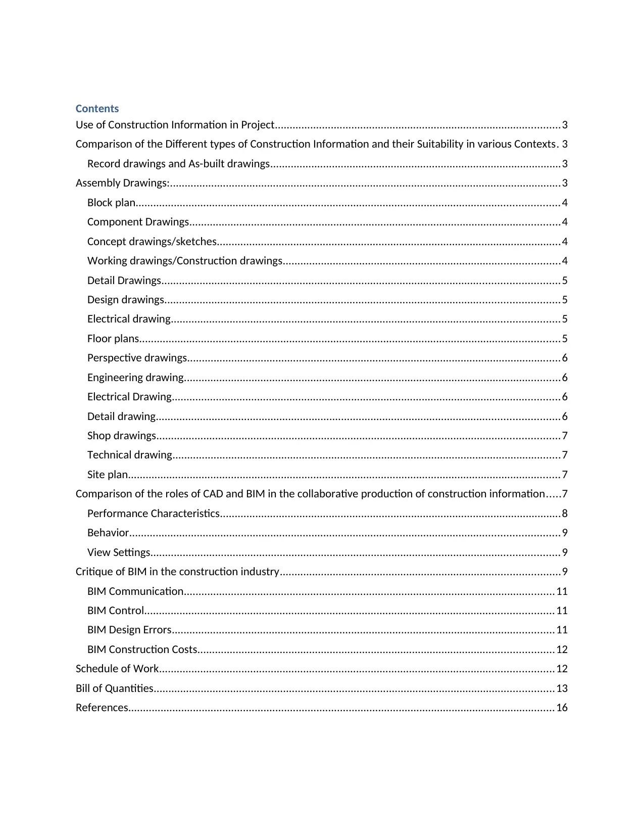
Contents
Use of Construction Information in Project.................................................................................................3
Comparison of the Different types of Construction Information and their Suitability in various Contexts. 3
Record drawings and As-built drawings...................................................................................................3
Assembly Drawings:.....................................................................................................................................3
Block plan................................................................................................................................................4
Component Drawings..............................................................................................................................4
Concept drawings/sketches.....................................................................................................................4
Working drawings/Construction drawings..............................................................................................4
Detail Drawings.......................................................................................................................................5
Design drawings......................................................................................................................................5
Electrical drawing....................................................................................................................................5
Floor plans...............................................................................................................................................5
Perspective drawings...............................................................................................................................6
Engineering drawing................................................................................................................................6
Electrical Drawing....................................................................................................................................6
Detail drawing.........................................................................................................................................6
Shop drawings.........................................................................................................................................7
Technical drawing....................................................................................................................................7
Site plan...................................................................................................................................................7
Comparison of the roles of CAD and BIM in the collaborative production of construction information.....7
Performance Characteristics....................................................................................................................8
Behavior..................................................................................................................................................9
View Settings...........................................................................................................................................9
Critique of BIM in the construction industry...............................................................................................9
BIM Communication..............................................................................................................................11
BIM Control...........................................................................................................................................11
BIM Design Errors..................................................................................................................................11
BIM Construction Costs.........................................................................................................................12
Schedule of Work......................................................................................................................................12
Bill of Quantities........................................................................................................................................13
References.................................................................................................................................................16

⊘ This is a preview!⊘
Do you want full access?
Subscribe today to unlock all pages.

Trusted by 1+ million students worldwide
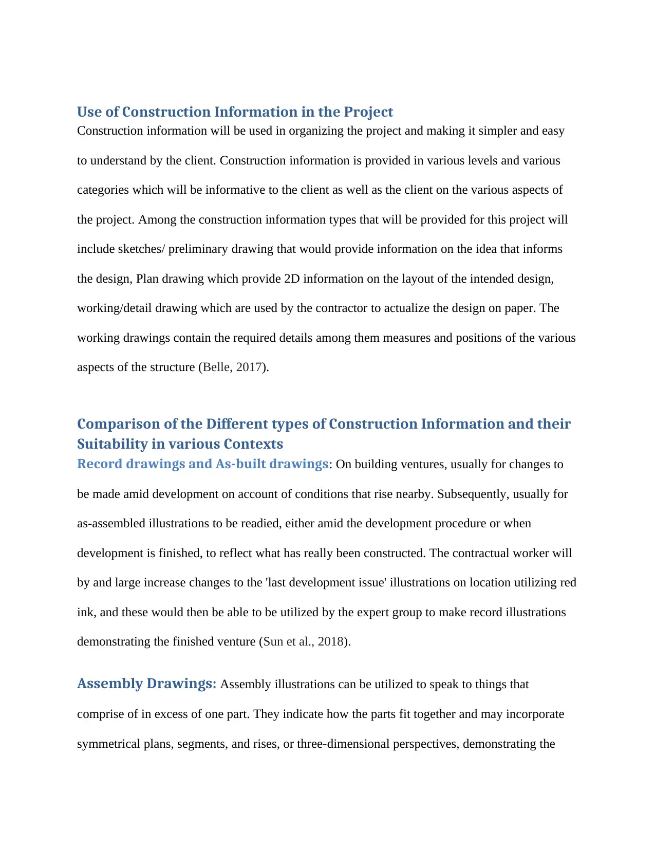
Use of Construction Information in the Project
Construction information will be used in organizing the project and making it simpler and easy
to understand by the client. Construction information is provided in various levels and various
categories which will be informative to the client as well as the client on the various aspects of
the project. Among the construction information types that will be provided for this project will
include sketches/ preliminary drawing that would provide information on the idea that informs
the design, Plan drawing which provide 2D information on the layout of the intended design,
working/detail drawing which are used by the contractor to actualize the design on paper. The
working drawings contain the required details among them measures and positions of the various
aspects of the structure (Belle, 2017).
Comparison of the Different types of Construction Information and their
Suitability in various Contexts
Record drawings and As-built drawings: On building ventures, usually for changes to
be made amid development on account of conditions that rise nearby. Subsequently, usually for
as-assembled illustrations to be readied, either amid the development procedure or when
development is finished, to reflect what has really been constructed. The contractual worker will
by and large increase changes to the 'last development issue' illustrations on location utilizing red
ink, and these would then be able to be utilized by the expert group to make record illustrations
demonstrating the finished venture (Sun et al., 2018).
Assembly Drawings: Assembly illustrations can be utilized to speak to things that
comprise of in excess of one part. They indicate how the parts fit together and may incorporate
symmetrical plans, segments, and rises, or three-dimensional perspectives, demonstrating the
Paraphrase This Document
Need a fresh take? Get an instant paraphrase of this document with our AI Paraphraser
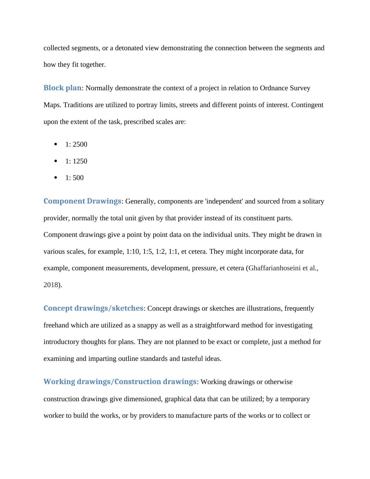
collected segments, or a detonated view demonstrating the connection between the segments and
how they fit together.
Block plan: Normally demonstrate the context of a project in relation to Ordnance Survey
Maps. Traditions are utilized to portray limits, streets and different points of interest. Contingent
upon the extent of the task, prescribed scales are:
1: 2500
1: 1250
1: 500
Component Drawings: Generally, components are 'independent' and sourced from a solitary
provider, normally the total unit given by that provider instead of its constituent parts.
Component drawings give a point by point data on the individual units. They might be drawn in
various scales, for example, 1:10, 1:5, 1:2, 1:1, et cetera. They might incorporate data, for
example, component measurements, development, pressure, et cetera (Ghaffarianhoseini et al.,
2018).
Concept drawings/sketches: Concept drawings or sketches are illustrations, frequently
freehand which are utilized as a snappy as well as a straightforward method for investigating
introductory thoughts for plans. They are not planned to be exact or complete, just a method for
examining and imparting outline standards and tasteful ideas.
Working drawings/Construction drawings: Working drawings or otherwise
construction drawings give dimensioned, graphical data that can be utilized; by a temporary
worker to build the works, or by providers to manufacture parts of the works or to collect or
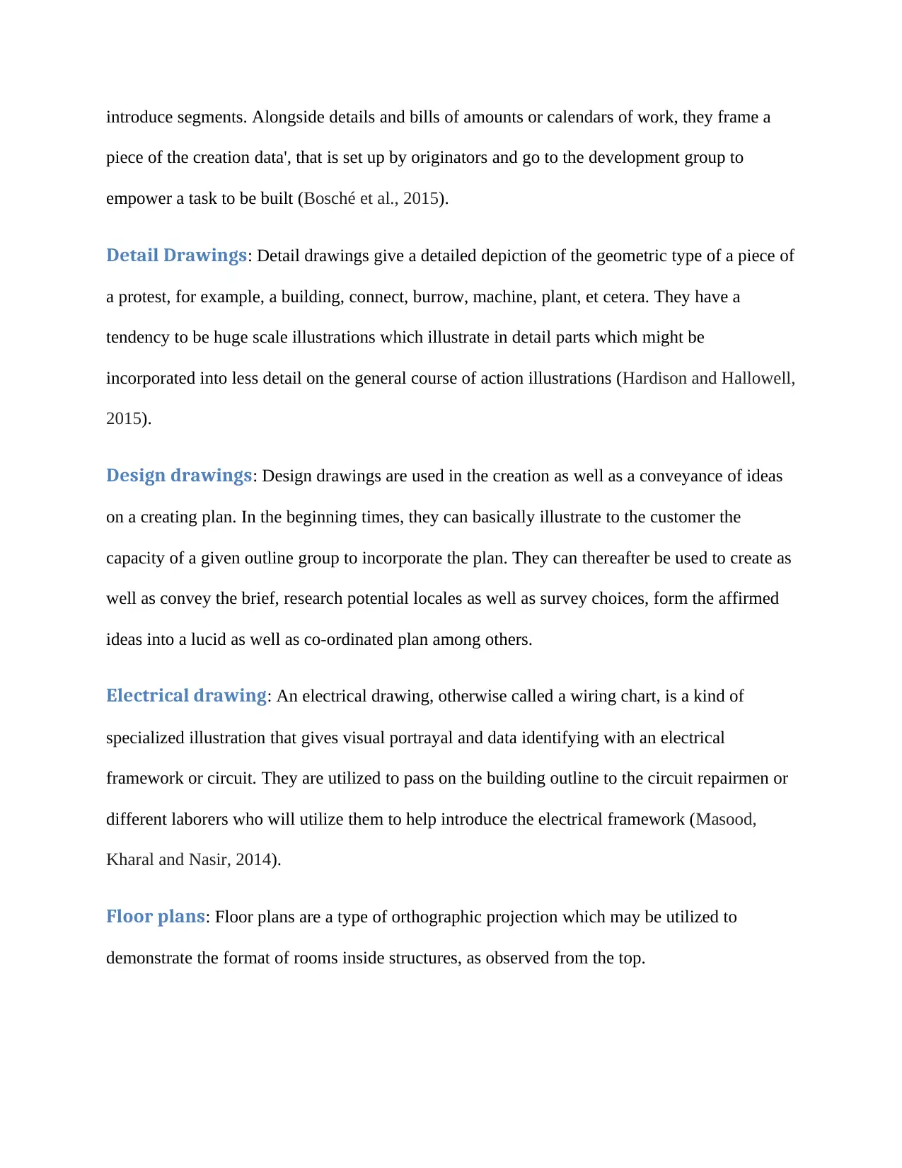
introduce segments. Alongside details and bills of amounts or calendars of work, they frame a
piece of the creation data', that is set up by originators and go to the development group to
empower a task to be built (Bosché et al., 2015).
Detail Drawings: Detail drawings give a detailed depiction of the geometric type of a piece of
a protest, for example, a building, connect, burrow, machine, plant, et cetera. They have a
tendency to be huge scale illustrations which illustrate in detail parts which might be
incorporated into less detail on the general course of action illustrations (Hardison and Hallowell,
2015).
Design drawings: Design drawings are used in the creation as well as a conveyance of ideas
on a creating plan. In the beginning times, they can basically illustrate to the customer the
capacity of a given outline group to incorporate the plan. They can thereafter be used to create as
well as convey the brief, research potential locales as well as survey choices, form the affirmed
ideas into a lucid as well as co-ordinated plan among others.
Electrical drawing: An electrical drawing, otherwise called a wiring chart, is a kind of
specialized illustration that gives visual portrayal and data identifying with an electrical
framework or circuit. They are utilized to pass on the building outline to the circuit repairmen or
different laborers who will utilize them to help introduce the electrical framework (Masood,
Kharal and Nasir, 2014).
Floor plans: Floor plans are a type of orthographic projection which may be utilized to
demonstrate the format of rooms inside structures, as observed from the top.
⊘ This is a preview!⊘
Do you want full access?
Subscribe today to unlock all pages.

Trusted by 1+ million students worldwide

They might be set up as a major aspect of the planning procedure, or to give directions to
development, frequently connected with different illustrations, calendars, and particulars.
Perspective drawings: Viewpoint drawing is a strategy for portraying three-dimensional
volumes and spatial connections dependent on the eye level and vanishing point (or focuses) of
the viewer. It may provide a real picture of what a volume or space will be like in general terms.
Developing viewpoint illustrations of structures is greatly entangled, yet has been tremendously
streamlined as of late by the advancement of computer-aided design (CAD), building
information modeling (BIM) as well as different types of computer-generated imagery (CGI)
(Alwan, Jones, and Holgate, 2017).
Engineering drawing: An engineering drawing is a type of drawing that is used in the
illustration of the features of building items or parts. Ordinarily, the motivation behind a
designing attracting is to plainly and precisely catch every geometric element of an item or part
with the goal that a maker or designer can create the required thing.
Electrical Drawing: An electrical drawing, otherwise called a wiring outline, is a sort of
specialized illustration that gives visual portrayal and data identifying with an electrical
framework or circuit. They are utilized to pass on the building outline to the circuit testers or
different laborers who will utilize them to help introduce the electrical framework.
Detail drawing: Detail drawings give a nitty-gritty depiction of the geometric type of a piece
of a question, for example, a building, connect, burrow, machine, plant among others. They have
a tendency to be huge scale illustrations which demonstrate in detail parts which might be
incorporated into less detail on the general course of action illustrations (Hardin and McCool,
2015).
Paraphrase This Document
Need a fresh take? Get an instant paraphrase of this document with our AI Paraphraser
Shop drawings: Shop drawings could be generated by workers, subcontractors, providers,
manufacturers or fabricators (Hardison and Hallowell, 2015). They, for the most part, identify
with pre-created segments, indicating how they should be fabricated or introduced. They take
plan goal illustrations as well as particulars planned by the undertaking configuration group and
generate them to look in detail how the components will actually be produced, manufactured,
collected or introduced.
Technical drawing: The word 'technical drawing' has an exceptionally wide significance,
alluding to any illustration that passes on the manner in which that something capacities or how
it is built. Specialized illustrations are expected to pass on one particular importance, rather than
aesthetic illustrations which are expressive and might be deciphered in various ways. Most
illustrations arranged amid the outline and development of structures may be viewed as
specialized illustrations (Azhar, Khalfan, and Maqsood, 2015).
Site plan: A site plan is an elaborate scale drawing which illustrates to the full extent the site
for an existing or suggested development. Site designs in addition to area designs may be
fundamental for planning functions. As a general guide, site plans would be generated following
the progress of the studies of the work area as well as site analysis.
Comparison of the roles of CAD and BIM in the collaborative production
of construction information
CAD is an abbreviation for computer-aided design and encompasses the use of computers to aid
in the creation of documents and designs that are linked to a given project. CAD enables brings
together numerous designs so that they can fit into a single larger unit. Initially, CAD enabled the
creation of 2D drawings including floor plants but with evolution, it possible to generate full 3D
models which provide an accurate representation of the intended ideas. The change into 3D has
led to a lot of transformation for architecture as it has enabled the generation of very complex
models. Still, clients are able to use such models to gain a better understanding of the work that
has been done by their designers. CAD has enabled speeding up of work is the obstruction
industry. As at the moment, designers are able to move from the concept to the final design and
manufacture within a shorter while in comparison with the past (Le, Er, and Sankaran, 2018).
While in most case Building Information Modelling is perceived as a natural evolution of CAD,
it should be made clear that BIM is not a kind of CAD package and instead of a design
methodology that may be used independently of CAD. BIM is composed of two main aspects:
sustainability and collaboration. BIM enables the design to bring the entire designs CAD model
inclusive into one database. Through the use of the cloud, BIM offers access to this database to
every member of a project. It enables members of a project to work on the same models that in
turn offers opportunities for quick changes. When properly adopted, BIM aids the whole team in
the visualization of the project; one of the major benefits of BIM in construction. This is
attributed to the sustainability aspect of BIM. The methodology enables a designer to design
each aspect of a building. Besides the building, BIM models are often accompanied by electrical
wiring as well as other significant design aspects. This generates a digital illustration that is more
realistic of final design product in a design process (Wu, Wang, and Wang, 2016).
The differences in CAD and BIM roles can be grouped into three:
Performance Characteristics: CAD files are often complex in nature and containing a
large amount of information among them characteristic of performances. Performance
characteristics are essential in ascertaining longevity and reliability. Performance characteristics
⊘ This is a preview!⊘
Do you want full access?
Subscribe today to unlock all pages.

Trusted by 1+ million students worldwide
often consume a lot of file space and would by far and large be purged during the conversion of a
CAD into a BIM. An end user of the files that is looking at such files would either need to
acquire a separate spec sheet or most likely contact a different vendor.
Behavior: BIM files are often designed to behave in defined ways which are factors of their
unique purpose as well as requires for connection. This means that the various parts of a model
are familiar with its task. An example would be a light fixture that knows or has to be attached to
a ceiling or wall as well as the electrical system. Upon making alterations to the model, these
components adjust themselves as well in logical manners
View Settings: CAD models often have just a single visual representation; highly detailed.
BIM models, on the other hand, are often designed for plasticity which means they can be
zoomed in and out, contracted or expanded among others. An introduction of a static, high detail
part like CAD model into the fluid, dynamic BIM model would enable the CAD image to be
viewed as is anticipated, in full detail at a single level of zoom. Adjustments to the scale of the
model slightly would lead to a blurring of the CAD components, even as a drastic adjustment to
the scale in a result in discoloration of the image, making them misshape, disappear from the
screen or look like a black splotch (Hardison and Hallowell, 2015).
Critique of BIM in the construction industry
BIM software has come up as one extraordinary tool allowing the decreased cost of development
as well as accelerating development projects. BIM is able to aid in avoiding missteps should an
honest to goodness agreement labor between colleagues is accurately inspected as well as shared.
BIM programming is able to separate as well as offer a strong comprehension of a given project
investment which may be executed by contractual workers as well as subcontractors. When used
Paraphrase This Document
Need a fresh take? Get an instant paraphrase of this document with our AI Paraphraser
at such a point in an appropriate manner, BIM may decrease project period, expenses as well as
claims (Ortiz, Castells and Sonnemann, 2009).
In the current audit, the off chance that there is skepticism among the task group individuals
about the significance and advantages of BIM on development ventures, tasteful results won't be
gotten. BIM's best speculation zones incorporate equipment, programming and inside
community improvement BIM work process (Hardison and Hallowell, 2015). The BIM
difficulties can be sorted as
specialized difficulties
skills and preparing challenges
legal procedural difficulties; and
An economy which can hinder the organizations from up gradation of their accessible
frameworks to a framework which is BIM situated.
Certain semi unmistakable points of interest in the development business are data accessibility,
efficiency and moved forward basic leadership capacity. The immaterial preferences incorporate
focused advantages; advertise access and better hazard administration (Ortiz, Castells and
Sonnemann, 2009). Difficulties of the impalpable contemplations incorporate the figuring of
financial terms. These investigations are suitable for estimation and impulse. Besides, these
points of interest are mined from business strategies and purposes. The free articulation to
emotionally supportive network targets is most certainly not given. The absence of formal
philosophies or on the other hand methodology to set up a BIM business case results in uneven
hypothesis and ill-advised estimation. Methodologies have been advanced to survey the data
frameworks. Be that as it may, the majority of them are prescriptive and receptive in nature,
contingent upon observation esteems (Ashworth and Perera, 2018).
BIM Communication: Among the issues putting into practice BIM as a fundamental aspect
of an individual’s task is the joint effort as well as access to the model by everyone needed
within the project phases. While Architects may use BIM to create an exemplary building,
diminishing financial expenses, as well as materials, should the design approach when the
assembly is being structured is not directed to the GC, cases, as well as challenges will emerge at
that point.
BIM Control: When BIM has been created and appropriated to venture individuals, watchful
precautionary actions have to be adopted to lessen the chances of resulting changes or variations
by unapproved individuals. The risk associated with altering a BIM demonstrate has changed in
an on-going issue on substantial development projects advantage, without sharing the plans to
the entire meeting. A collection of pioneers must be relegated and would be the key consented
client who may alter the BIM show (Ashworth and Perera, 2018).
BIM Design Errors: Who should be held responsible in case the building is established to
neglect consent to the on-going or the current building codes? Should that be the role of a GC? Is
the inability of the architect to consent able to make him be held at risk? There is a weak
connection between duties since every meeting has developed an interest in planning stages,
amendments as well as a contribution to BIM show (Ortiz, Castells and Sonnemann, 2009). In a
few occasions, legal issues may move towards gaining activation by cases displayed by the GC,
owing to distortion or broken structures. Such kinds of mistakes may be illustrative of the
⊘ This is a preview!⊘
Do you want full access?
Subscribe today to unlock all pages.

Trusted by 1+ million students worldwide
1 out of 19
Related Documents
Your All-in-One AI-Powered Toolkit for Academic Success.
+13062052269
info@desklib.com
Available 24*7 on WhatsApp / Email
![[object Object]](/_next/static/media/star-bottom.7253800d.svg)
Unlock your academic potential
Copyright © 2020–2026 A2Z Services. All Rights Reserved. Developed and managed by ZUCOL.


