Comprehensive Analysis and Design of a DC Motor Control System
VerifiedAdded on 2020/05/28
|16
|1893
|327
Report
AI Summary
This report provides a comprehensive analysis of a DC motor control system. It begins with an overview of DC motor speed regulation, explaining how armature voltage variation controls speed. The report then delves into the input-output voltage relationship of an inverting amplifier, detailing its function in the system. The step response of the DC motor is examined to understand its dynamic characteristics, including electrical and mechanical time constants. The investigation of overall system dynamics focuses on closed-loop control, including PI controllers and their parameters. The report also explores the design of control schemes, such as time ratio control and chopper circuits, to achieve precise motor control. Motor dynamics, including torque and speed characteristics, are also analyzed, along with references to relevant literature.

control system
Paraphrase This Document
Need a fresh take? Get an instant paraphrase of this document with our AI Paraphraser
Table of Contents
1. DC motor speed regulation.......................................................................................................2
2. Input –output voltage relationship of an inverting amplifier....................................................3
3. Step response.............................................................................................................................5
4. Investigation of overall system dynamics.................................................................................7
5. Control scheme designed........................................................................................................11
1
Stage -2
1. DC motor speed regulation
By varying the applied armature voltage the speed regulation is controlled. A variable
speed DC drive is designed to supply a required DC voltage to the armature DC drive speed
variation. The field supply is maintained constant as it is voltage controlled.
Cascade control structure with closed loop method is used. To achieve the fast rejection of
disturbance which propagates to other parts of the loop cascade control should be completed.
From the innermost current loop which proceeds to the slowest outer speed loop started
from the design loop. Dependence on the inner loop the outer loop is performed. The inner loop
dynamics is modified as the impact on the outer loop and its performance can be reduced.
System dynamics
In the closed loop system the accuracy and dynamic response are better. The acceleration and
the deceleration of the motor can be controlled by the closed loop system. The output is
compared with reference voltage according to the requirement.
There are two closed path in the control scheme. One is inner current loop and the other is
outer speed control loop. Both loop are controlled with the controller according to the
requirements of the system.
When the motor is accelerated the armature current tends to increase the large value. By
limiting the maximum current command voltage a current limit is obtained in this system.
An error signal is produced when the gate pulse generator to the advance the firing pulses and
increase in the output voltage when the motor speed drops below the set point. Then it
randomly increases to the desired level.
Constant torque
The Torque speed of DC motor characteristics should match with the load to where the drive
is to be connected. In the bottom base speed the armature voltage controlled is applied. Speed
is Increased when the armature voltage is increased.
To increase the speed above the base speed the field flux is used. The field flux is reduced
when the armature voltage is kept constant at its rated voltage.
2
⊘ This is a preview!⊘
Do you want full access?
Subscribe today to unlock all pages.

Trusted by 1+ million students worldwide
In the armature circuit no extra power losses takes place. To control the base speed armature
voltage control method is assumed, across the armature voltage very small speed should not
be given which is higher than the rated voltage.
2. Input –output voltage relationship of an inverting amplifier
Inverting Amplifier
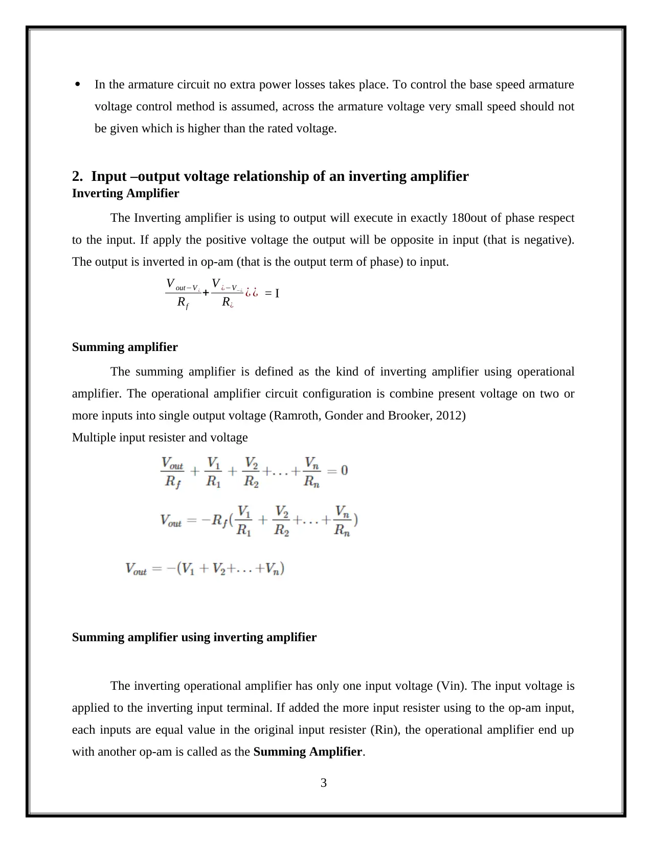
The Inverting amplifier is using to output will execute in exactly 180out of phase respect
to the input. If apply the positive voltage the output will be opposite in input (that is negative).
The output is inverted in op-am (that is the output term of phase) to input.
V out−V ¿
Rf
+ V ¿−V−¿
R¿
¿ ¿ = I
Summing amplifier
The summing amplifier is defined as the kind of inverting amplifier using operational
amplifier. The operational amplifier circuit configuration is combine present voltage on two or
more inputs into single output voltage (Ramroth, Gonder and Brooker, 2012)
Multiple input resister and voltage
Summing amplifier using inverting amplifier
The inverting operational amplifier has only one input voltage (Vin). The input voltage is
applied to the inverting input terminal. If added the more input resister using to the op-am input,
each inputs are equal value in the original input resister (Rin), the operational amplifier end up
with another op-am is called as the Summing Amplifier.
3
Paraphrase This Document
Need a fresh take? Get an instant paraphrase of this document with our AI Paraphraser
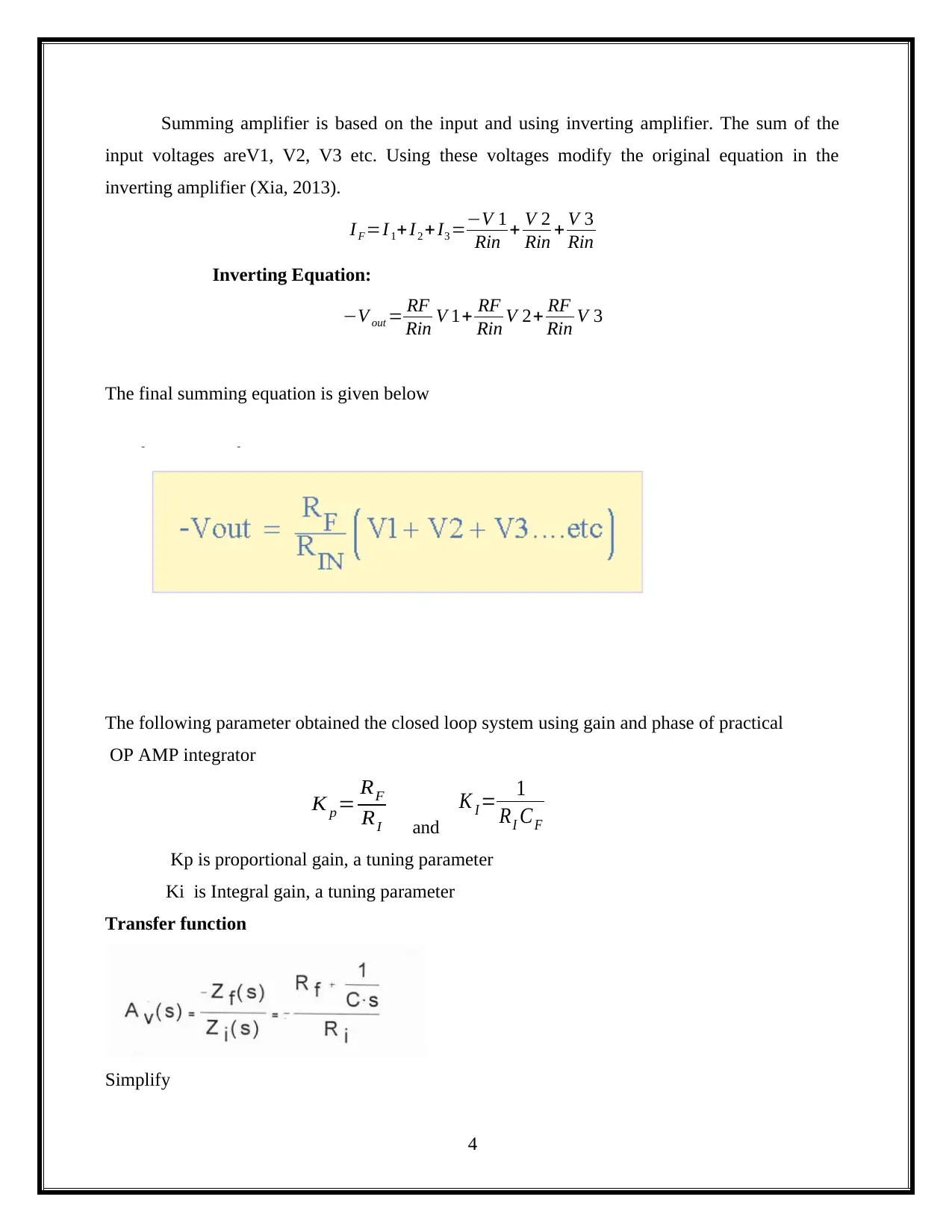
Summing amplifier is based on the input and using inverting amplifier. The sum of the
input voltages areV1, V2, V3 etc. Using these voltages modify the original equation in the
inverting amplifier (Xia, 2013).
I F =I 1+ I2 + I3 =−V 1
Rin + V 2
Rin + V 3
Rin
Inverting Equation:
−V out = RF
Rin V 1+ RF
Rin V 2+ RF
Rin V 3
The final summing equation is given below
The following parameter obtained the closed loop system using gain and phase of practical
OP AMP integrator
K p= RF
RI and
K I = 1
RI CF
Kp is proportional gain, a tuning parameter
Ki is Integral gain, a tuning parameter
Transfer function
Simplify
4
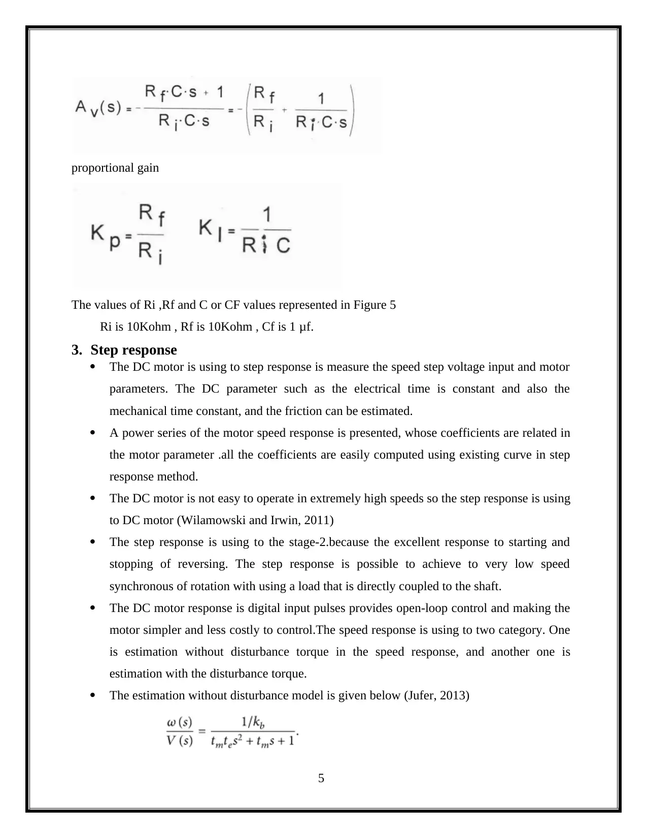
proportional gain
The values of Ri ,Rf and C or CF values represented in Figure 5
Ri is 10Kohm , Rf is 10Kohm , Cf is 1 μf.
3. Step response
The DC motor is using to step response is measure the speed step voltage input and motor
parameters. The DC parameter such as the electrical time is constant and also the
mechanical time constant, and the friction can be estimated.
A power series of the motor speed response is presented, whose coefficients are related in
the motor parameter .all the coefficients are easily computed using existing curve in step
response method.
The DC motor is not easy to operate in extremely high speeds so the step response is using
to DC motor (Wilamowski and Irwin, 2011)
The step response is using to the stage-2.because the excellent response to starting and
stopping of reversing. The step response is possible to achieve to very low speed
synchronous of rotation with using a load that is directly coupled to the shaft.
The DC motor response is digital input pulses provides open-loop control and making the
motor simpler and less costly to control.The speed response is using to two category. One
is estimation without disturbance torque in the speed response, and another one is
estimation with the disturbance torque.
The estimation without disturbance model is given below (Jufer, 2013)
5
⊘ This is a preview!⊘
Do you want full access?
Subscribe today to unlock all pages.

Trusted by 1+ million students worldwide
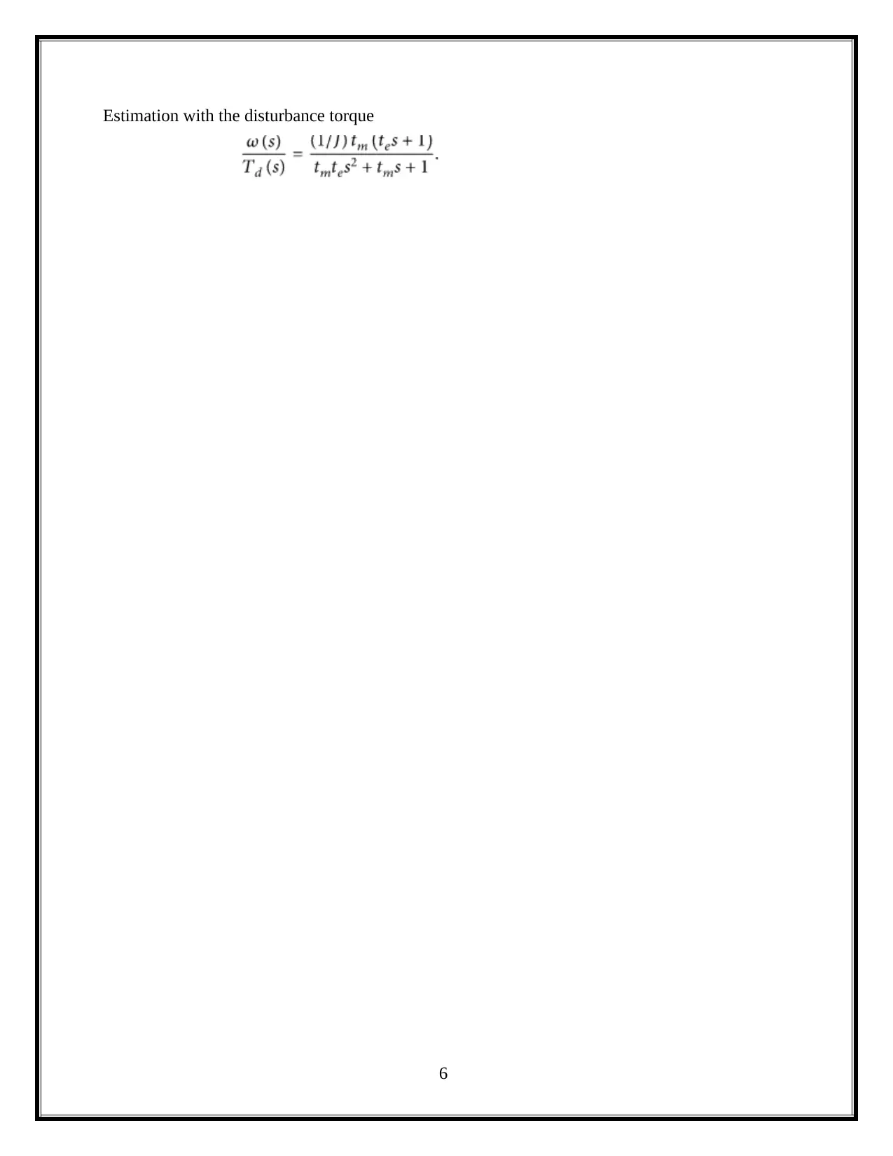
Estimation with the disturbance torque
6
6
Paraphrase This Document
Need a fresh take? Get an instant paraphrase of this document with our AI Paraphraser
Stage-3
4. Investigation of overall system dynamics
The investigation of overall system dynamics for closed loop systems output of the current
control loop is the reference voltage for the pulse width modulation block. It represents in volts
and its amplidute should be the same order as the grid voltage. Setting the eferendce for the
PWM, it should be normalize the voltage of DC.
The PI controller mathematical expression expressed as
If e(t) is known as the error signal and u(t) is output PID controller it as the sum of three terms.
1 proportional term
2 Intergral Term
3 Derivative term
Proportional term
The Kp e(t) and Ki is called proportional gain (that is response to current error).
Intergral Term
Ki intergral is[0,t] e()d , Ki is intergral gain( that is response to error accumulated so far).
Derivative Term
KD(d/dt)e(t),Kd is the derivative gain (tha is response to current rate of change of error).
Calcualtion for Kp and Ki
RF = 6.3 K ohm, RI = 30.6 K ohm
Proportional gain KP = RF/RI
= 6.3/30.6
KP =0.205
Integral gain KI = 1/ RI CF
= 1/0.0306
7
KI = 32.67
controller RF RI Kp Ki
PI controller 6.3 K ohm 30.6 K ohm 0.205 32.67
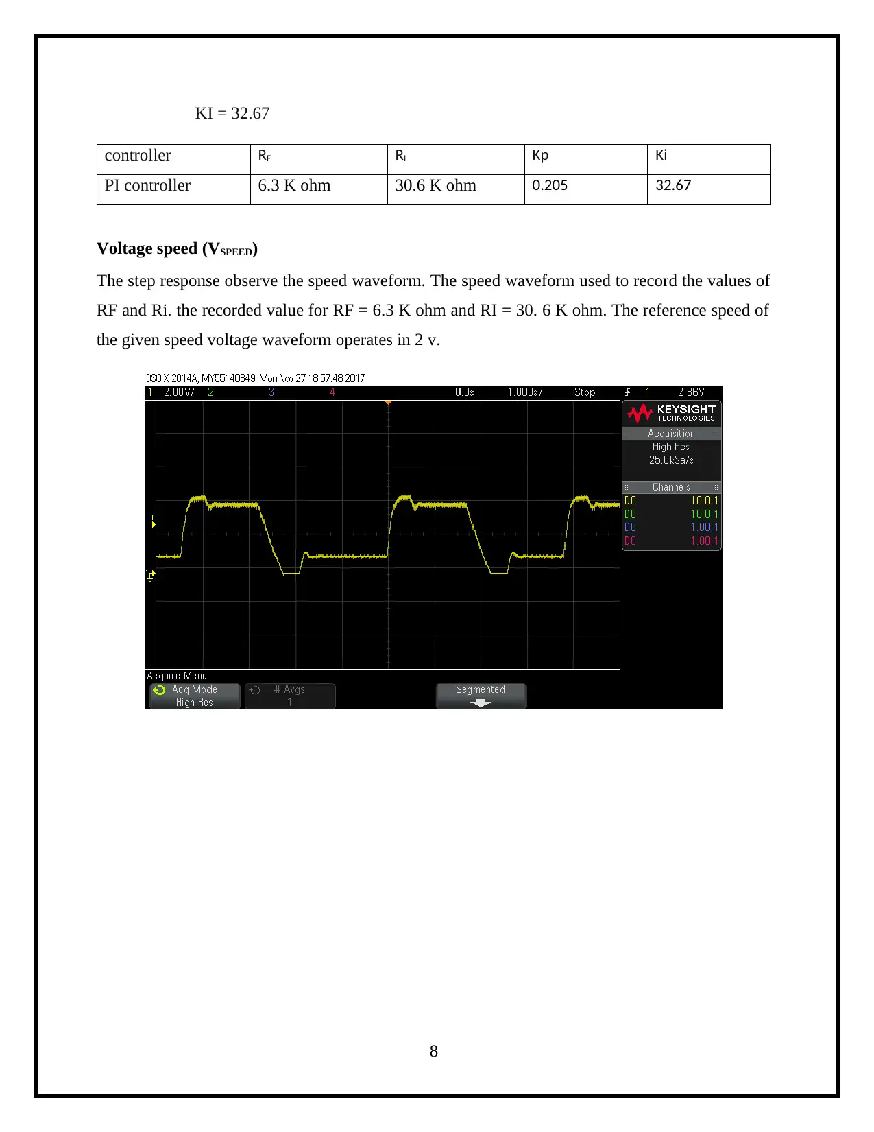
Voltage speed (VSPEED)
The step response observe the speed waveform. The speed waveform used to record the values of
RF and Ri. the recorded value for RF = 6.3 K ohm and RI = 30. 6 K ohm. The reference speed of
the given speed voltage waveform operates in 2 v.
8
⊘ This is a preview!⊘
Do you want full access?
Subscribe today to unlock all pages.

Trusted by 1+ million students worldwide
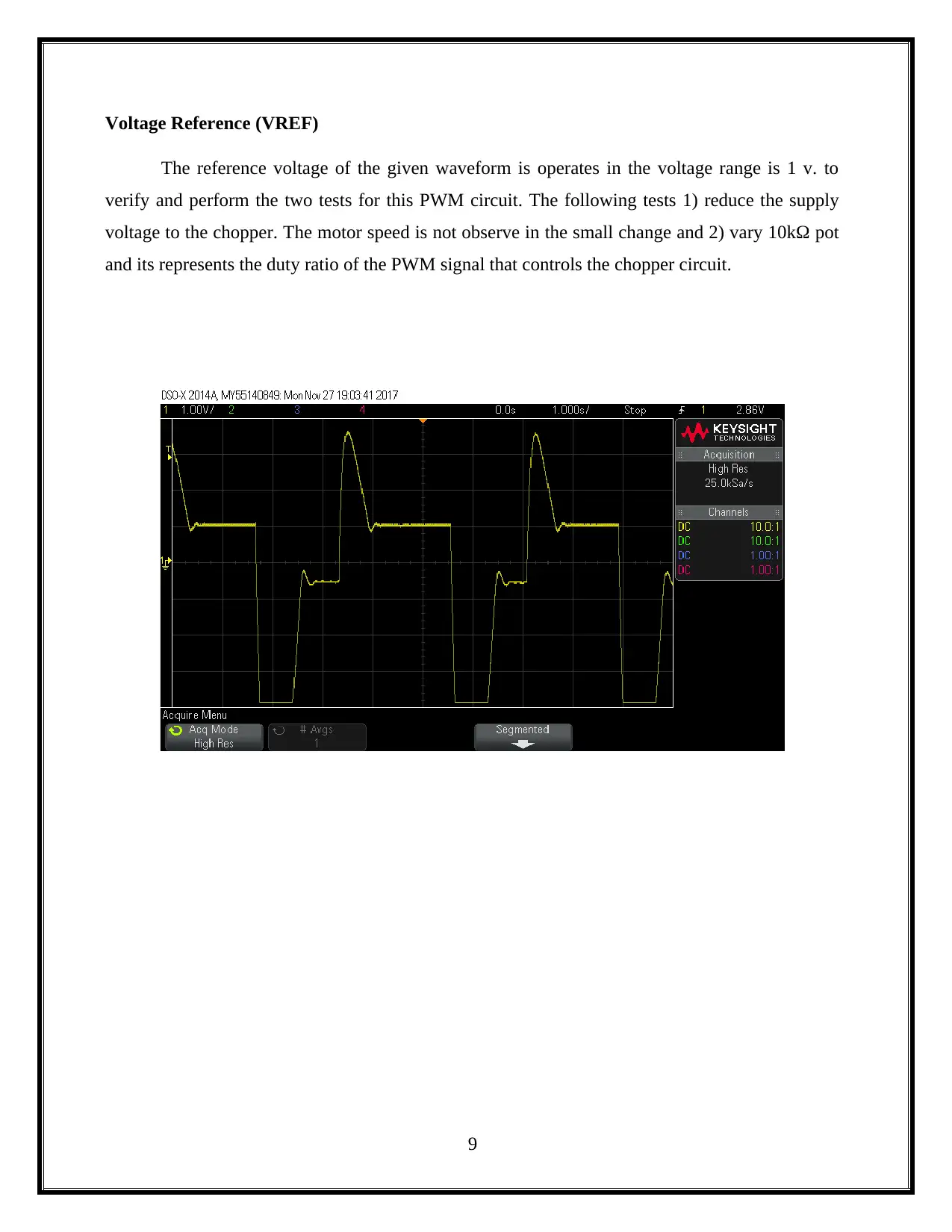
Voltage Reference (VREF)
The reference voltage of the given waveform is operates in the voltage range is 1 v. to
verify and perform the two tests for this PWM circuit. The following tests 1) reduce the supply
voltage to the chopper. The motor speed is not observe in the small change and 2) vary 10kΩ pot
and its represents the duty ratio of the PWM signal that controls the chopper circuit.
9
Paraphrase This Document
Need a fresh take? Get an instant paraphrase of this document with our AI Paraphraser
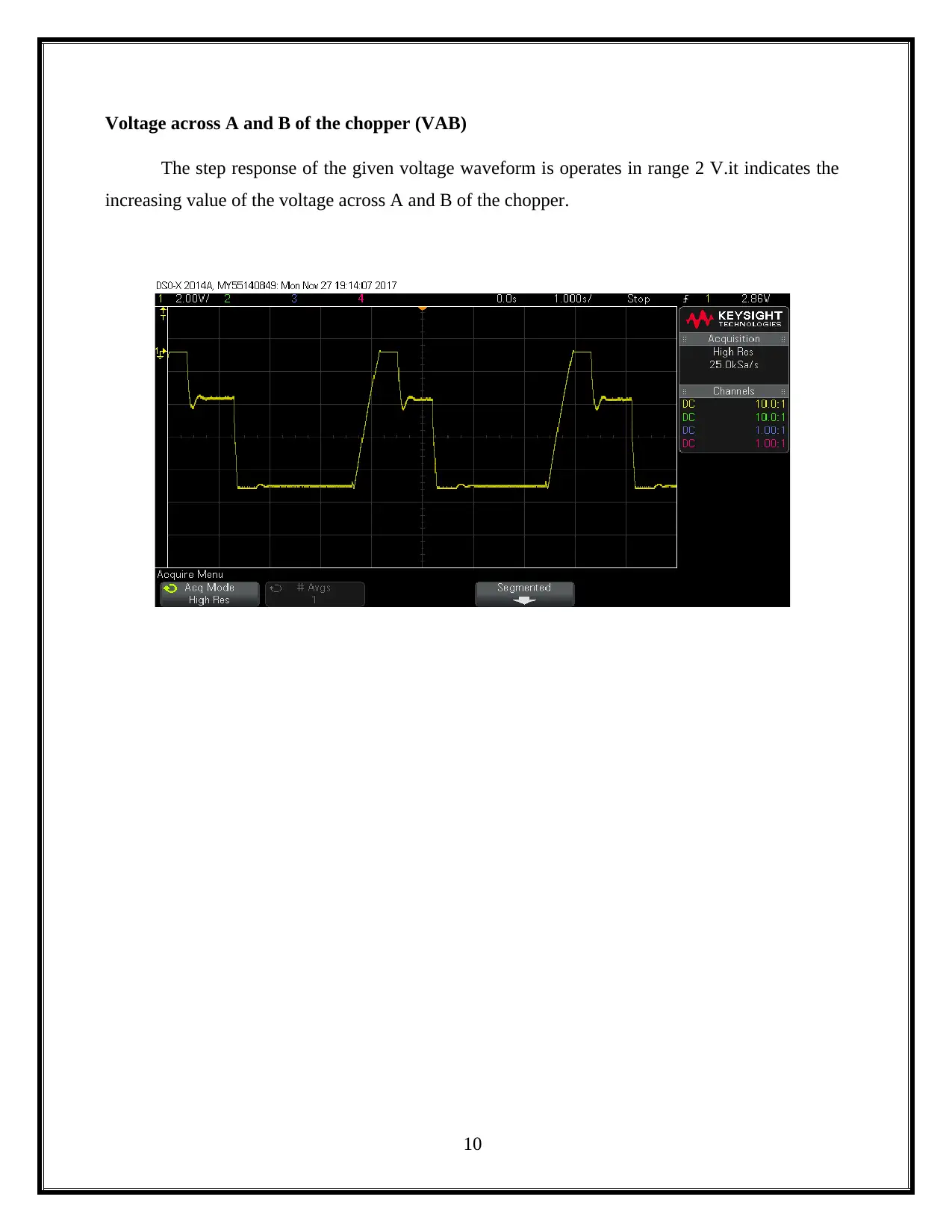
Voltage across A and B of the chopper (VAB)
The step response of the given voltage waveform is operates in range 2 V.it indicates the
increasing value of the voltage across A and B of the chopper.
10
The step response of the given voltage waveform is operates in range 2 V.it indicates the
increasing value of the voltage across A and B of the chopper.
10
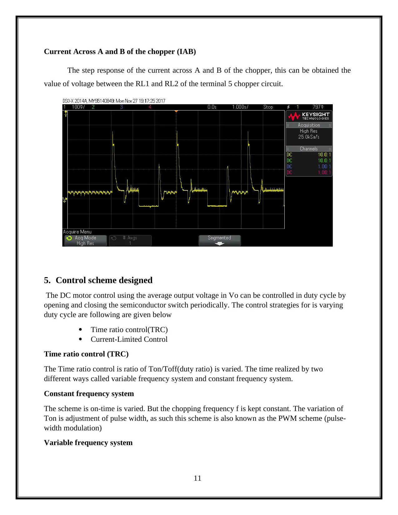
Current Across A and B of the chopper (IAB)
The step response of the current across A and B of the chopper, this can be obtained the
value of voltage between the RL1 and RL2 of the terminal 5 chopper circuit.
5. Control scheme designed
The DC motor control using the average output voltage in Vo can be controlled in duty cycle by
opening and closing the semiconductor switch periodically. The control strategies for is varying
duty cycle are following are given below
Time ratio control(TRC)
Current-Limited Control
Time ratio control (TRC)
The Time ratio control is ratio of Ton/Toff(duty ratio) is varied. The time realized by two
different ways called variable frequency system and constant frequency system.
Constant frequency system
The scheme is on-time is varied. But the chopping frequency f is kept constant. The variation of
Ton is adjustment of pulse width, as such this scheme is also known as the PWM scheme (pulse-
width modulation)
Variable frequency system
11
⊘ This is a preview!⊘
Do you want full access?
Subscribe today to unlock all pages.

Trusted by 1+ million students worldwide
1 out of 16
Related Documents
Your All-in-One AI-Powered Toolkit for Academic Success.
+13062052269
info@desklib.com
Available 24*7 on WhatsApp / Email
![[object Object]](/_next/static/media/star-bottom.7253800d.svg)
Unlock your academic potential
Copyright © 2020–2025 A2Z Services. All Rights Reserved. Developed and managed by ZUCOL.


