Speed Control of Induction Motor
Added on 2023-04-04
28 Pages4011 Words50 Views
Electric Machines 1
ELECTRICAL MACHINES
By Name
Course
Instructor
Institution
Location
Date
ELECTRICAL MACHINES
By Name
Course
Instructor
Institution
Location
Date

Electric Machines 2
Speed control of Induction motor
Abstract
Several induction motors are currently being used general purposes within the surroundings to
perform different activities. Their usage range from household machines to equipment to tools
used in several industrial activities. The induction motors are slowly becoming a vital and a
source of power that cannot be dispensable within several industries. There is a wide range of
performance capabilities that are needed for these induction motors. On the speed control
segment of the induction motors, it presents a very important functional organ for the induction
motors that generally requires a lot of attention and knowledge on how to achieve. Despite being
traditionally used in the services of fixed speed, its usage has evolved over the years and is
currently being used together with variable frequency drives (VFDs) in services of variable
speed. The VFDs provide necessary opportunities of energy savings for the already existing
induction motors as well future motors in applications such as compressor load, pump and torque
centrifugal fan. This research work provides a detailed explanation of the different working
principles of the induction motors as well as general methods of speed control for these devices.
The key features for the common control methods of induction motor speeds have also been
discussed.
Electric Machines 3
Table of Contents
Abstract...................................................................................................................................................2
1. Introduction.....................................................................................................................................4
1.1. Synchronous speed......................................................................................................................4
1.2. Operating principle of the induction motor..................................................................................5
2. Literature review..............................................................................................................................6
2.1. The equivalent circuit and control of speed of induction motor...................................................6
2.2. Induction motor and their torque speed analysis........................................................................12
2.3. Analysis of various methods for speed control of induction motors..........................................15
2.3.1. By changing stator Voltage....................................................................................................15
2.3.2. By changing stator Frequency................................................................................................19
2.3.3. By changing stator Voltage/Frequency Ratio.........................................................................20
3. Efficient Method of speed control.................................................................................................21
4. Methodology..................................................................................................................................22
4.1. Operation of inductors...............................................................................................................22
4.2. Slip............................................................................................................................................23
5. Conclusion.....................................................................................................................................24
References.............................................................................................................................................26
Electric Machines 4
1. Introduction
An induction motor basically represents a speed motor, implying that for the whole range of
loading, the change in speed for the induction motor is relatively low. It also commonly referred
to as asynchronous motor due to its ability to propel at a speed that is lower than its synchronous
speed (Barrero et al, 2012). It is an alternating current electric motor where the rotor electric
motor required in order to produce the torque is attained through electromagnetic induction from
the stator winding magnetic field. This implies that induction motors can be designed without
any electrical links to the rotor. The rotor of an induction motor can either be squirrel cage type
or the wounded type. The mostly used induction motors in most industrial drives are the 3-phase
squirrel cage type of induction motors. This is mainly due to the fact that they are more reliable,
self-starting and are generally economical.
1.1. Synchronous speed
Synchronous speed can be defined as the rotation speed for the magnetic field in any given rotary
machine. Synchronous speed often relies on the number of poles as well as the frequency of the
machine. The induction motor often operates at a speed that is generally lower than the
synchronous speed (Ben-Brahim, Tadakuma & Akdag, 2017). The rotating magnetic field is
produced in the stator. It will develop a flux in the rotor and thus enabling the rotor to rotate. As
a result of the lagging of the flux current in the rotor with the current of the flux in the stator, it
will be impossible for the rotor to attain its speed for the rotating magnetic field. This speed is
the synchronous speed.
The synchronous speed, ns for an AC motor basically represents the rate of rotation of the
magnetic field of the stator. It is given by the below expression;
Electric Machines 5
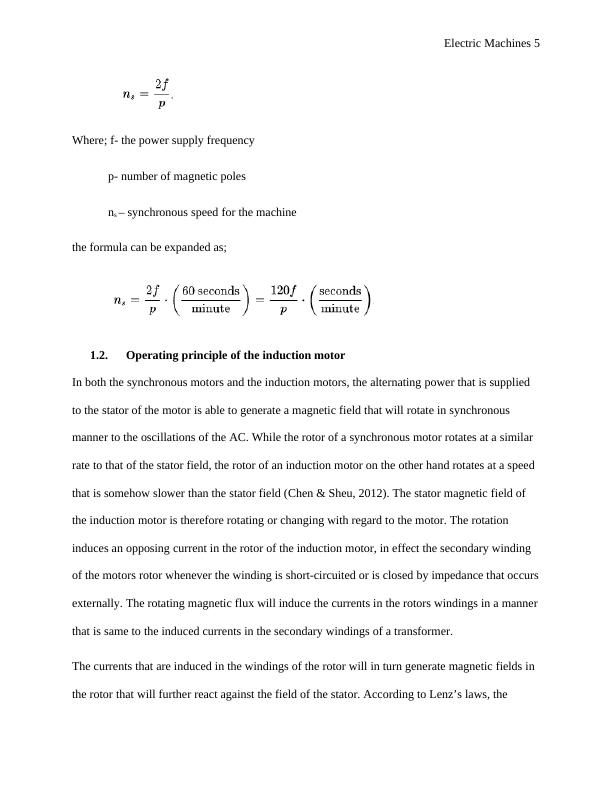
Where; f- the power supply frequency
p- number of magnetic poles
ns – synchronous speed for the machine
the formula can be expanded as;
1.2. Operating principle of the induction motor
In both the synchronous motors and the induction motors, the alternating power that is supplied
to the stator of the motor is able to generate a magnetic field that will rotate in synchronous
manner to the oscillations of the AC. While the rotor of a synchronous motor rotates at a similar
rate to that of the stator field, the rotor of an induction motor on the other hand rotates at a speed
that is somehow slower than the stator field (Chen & Sheu, 2012). The stator magnetic field of
the induction motor is therefore rotating or changing with regard to the motor. The rotation
induces an opposing current in the rotor of the induction motor, in effect the secondary winding
of the motors rotor whenever the winding is short-circuited or is closed by impedance that occurs
externally. The rotating magnetic flux will induce the currents in the rotors windings in a manner
that is same to the induced currents in the secondary windings of a transformer.
The currents that are induced in the windings of the rotor will in turn generate magnetic fields in
the rotor that will further react against the field of the stator. According to Lenz’s laws, the
Electric Machines 6
magnetic field direction that is developed will exist in such a way that it opposes current change
through the windings of the rotor. What causes the induced current in the windings of the rotor is
the stator magnetic field that is rotating. In order to oppose the change in rotor winding currents,
the rotor will begin to rotate in the direction of the magnetic field for the rotating stator (Feng,
Liu & Huang, 2014). The rotor will continue to accelerate up to a point where the magnitude of
the torque and the induced rotor current will balance to the mechanical load that is applied to the
rotor rotation. Given that the rotation at a synchronous speed will lead to no induced current of
the rotor, the operation of the induction motor will always be at a speed that is lower than the
synchronous speed. The slip or difference between the synchronous and the actual sped ranges
from about 0.5% to 5.0%. This is always for the standard design B torque induction motors
curves. Induction motor have an essential character of being solely developed by the process of
induction and not being excited independently as in DC or synchronous machines or even being
self-magnetized as in the case of magnetic motors that are permanent (Garces, 2010).
2. Literature review
2.1. The equivalent circuit and control of speed of induction motor
In order to understand the way the induction motor behaves in various conditions of operation, it
is important to develop an equivalent circuit for the motor. The equivalent circuit should be
developed the conditions of sinusoidal steady state operations. In the instance of a balanced three
phase operation, the equivalent circuit for any given phase will suffice. The equivalent circuit for
the induction motor is as shown below (Holtz & Quan, 2012).

End of preview
Want to access all the pages? Upload your documents or become a member.
Related Documents
Electrical Power & Drive Systems - Doclg...
|25
|2031
|44
Design and Fabrication of Three Phase Induction Motor with Microcontrollerlg...
|8
|1832
|205
Power Electronics : Assignmentlg...
|3
|729
|162
Synchronous Machines - Types, Operation, Phasor Diagram, Torque and Powerlg...
|3
|535
|313
The Fast Fourier Transform Spectrum Analyzerlg...
|10
|1896
|119
Wind Turbines Induction Generators (Doc)lg...
|14
|2434
|679