Electrical and Electronic Engineering Problems Solution Analysis
VerifiedAdded on 2023/01/20
|26
|2767
|56
Homework Assignment
AI Summary
This assignment provides detailed solutions to a range of electrical and electronic engineering problems. It begins with calculations involving series and parallel resistors, total current, and the application of Kirchhoff's laws to determine currents in various branches of a circuit. The solution then delves into circuit simplification using Thevenin's and Norton's theorems, calculating currents and voltage drops across different components. Further, the assignment explores the behavior of a capacitor in a circuit, calculating time constants and sketching voltage rise and decay curves. Finally, the assignment identifies and describes complex waveforms, including triangular and square waves, and explains their production from a pure sine wave. It also includes calculations for reactance, impedance, and phase angles in RLC circuits.
ELECTRICAL AND ELECTRONIC ENGINEERING PROBLEMS
By Name
Course
Instructor
Institution
Location
Date
By Name
Course
Instructor
Institution
Location
Date
Paraphrase This Document
Need a fresh take? Get an instant paraphrase of this document with our AI Paraphraser
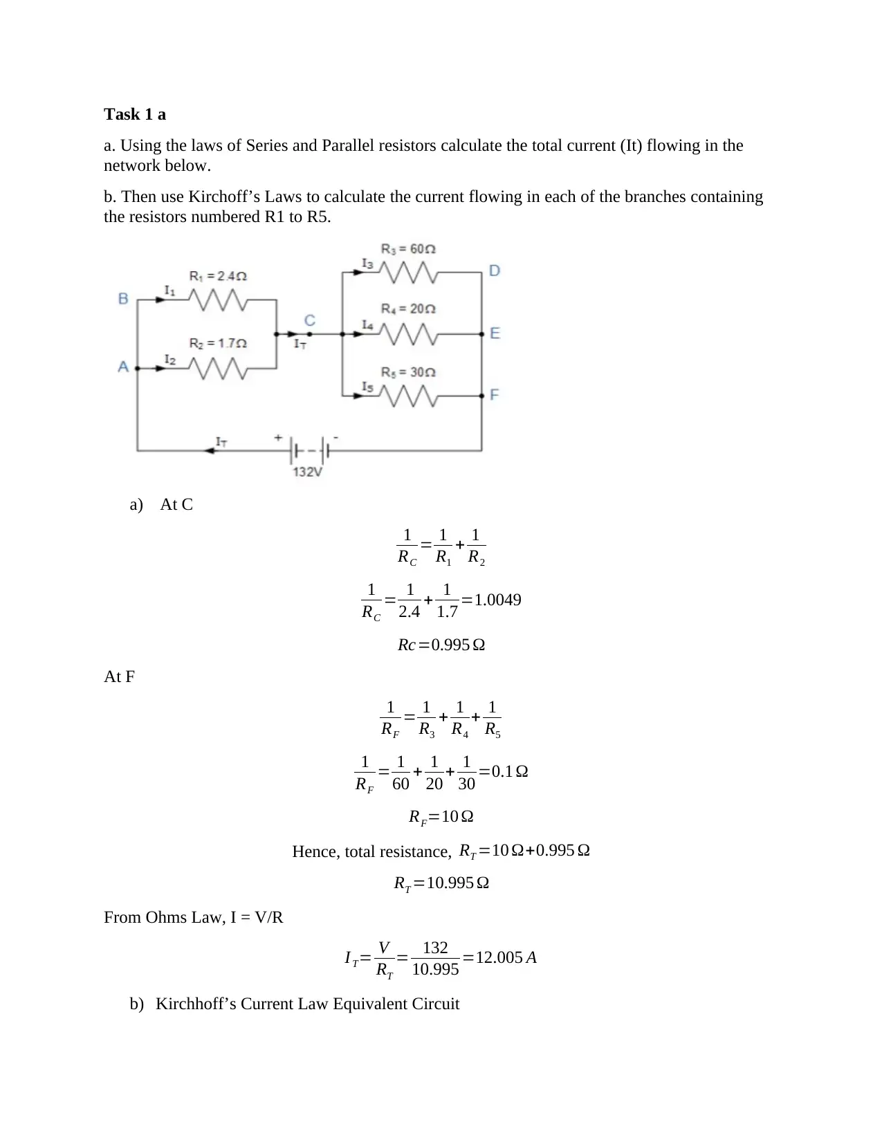
Task 1 a
a. Using the laws of Series and Parallel resistors calculate the total current (It) flowing in the
network below.
b. Then use Kirchoff’s Laws to calculate the current flowing in each of the branches containing
the resistors numbered R1 to R5.
a) At C
1
RC
= 1
R1
+ 1
R2
1
RC
= 1
2.4 + 1
1.7 =1.0049
Rc=0.995 Ω
At F
1
RF
= 1
R3
+ 1
R4
+ 1
R5
1
RF
= 1
60 + 1
20 + 1
30 =0.1 Ω
RF=10 Ω
Hence, total resistance, RT =10 Ω+0.995 Ω
RT =10.995 Ω
From Ohms Law, I = V/R
I T= V
RT
= 132
10.995 =12.005 A
b) Kirchhoff’s Current Law Equivalent Circuit
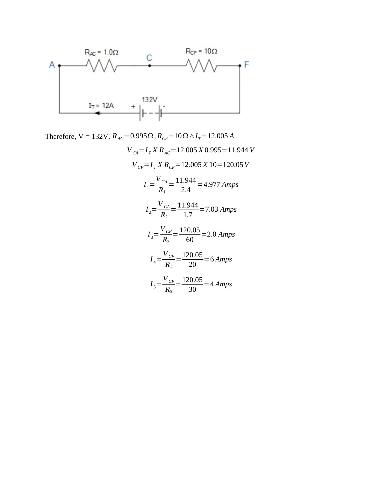
Therefore, V = 132V, RAC=0.995Ω , RCF=10 Ω∧IT =12.005 A
V CA=I T X RAC=12.005 X 0.995=11.944 V
V CF=I T X RCF=12.005 X 10=120.05 V
I 1=V CA
R1
= 11.944
2.4 =4.977 Amps
I 2=V CA
R2
= 11.944
1.7 =7.03 Amps
I3= V CF
R3
= 120.05
60 =2.0 Amps
I 4= V CF
R4
=120.05
20 =6 Amps
I 5= V CF
R5
= 120.05
30 =4 Amps
V CA=I T X RAC=12.005 X 0.995=11.944 V
V CF=I T X RCF=12.005 X 10=120.05 V
I 1=V CA
R1
= 11.944
2.4 =4.977 Amps
I 2=V CA
R2
= 11.944
1.7 =7.03 Amps
I3= V CF
R3
= 120.05
60 =2.0 Amps
I 4= V CF
R4
=120.05
20 =6 Amps
I 5= V CF
R5
= 120.05
30 =4 Amps
⊘ This is a preview!⊘
Do you want full access?
Subscribe today to unlock all pages.

Trusted by 1+ million students worldwide
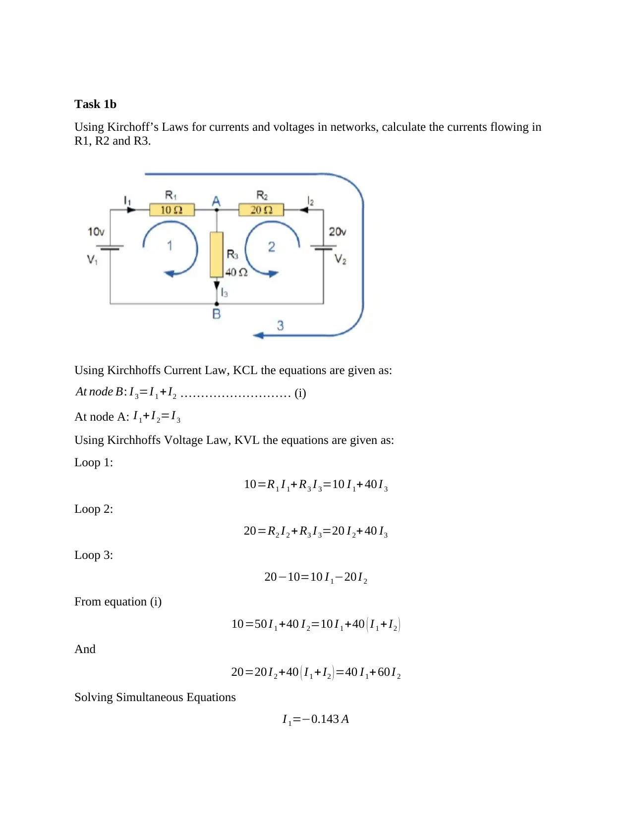
Task 1b
Using Kirchoff’s Laws for currents and voltages in networks, calculate the currents flowing in
R1, R2 and R3.
Using Kirchhoffs Current Law, KCL the equations are given as:
At node B: I 3=I 1 +I2 ……………………… (i)
At node A: I 1+ I 2=I 3
Using Kirchhoffs Voltage Law, KVL the equations are given as:
Loop 1:
10=R1 I 1+ R3 I3=10 I1+ 40 I 3
Loop 2:
20=R2 I2 + R3 I3=20 I 2+ 40 I3
Loop 3:
20−10=10 I 1−20 I 2
From equation (i)
10=50 I 1 +40 I 2=10 I 1 +40 ( I 1 +I2 )
And
20=20 I2 +40 ( I1 + I2 ) =40 I1+ 60 I 2
Solving Simultaneous Equations
I 1=−0.143 A
Paraphrase This Document
Need a fresh take? Get an instant paraphrase of this document with our AI Paraphraser
I 2=0.429 A
I 3=−0.143+0.429=0.286 A
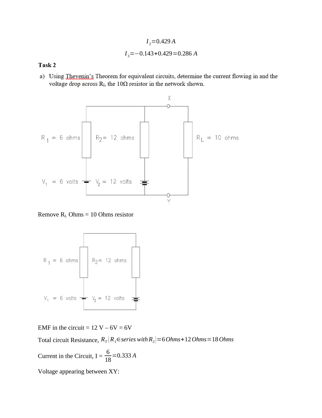
Remove RL Ohms = 10 Ohms resistor
EMF in the circuit = 12 V – 6V = 6V
Total circuit Resistance, RT ( R1∈series with R2 ) =6 Ohms+12 Ohms=18 Ohms
Current in the Circuit, I = 6
18 =0.333 A
Voltage appearing between XY:
I 3=−0.143+0.429=0.286 A
Remove RL Ohms = 10 Ohms resistor
EMF in the circuit = 12 V – 6V = 6V
Total circuit Resistance, RT ( R1∈series with R2 ) =6 Ohms+12 Ohms=18 Ohms
Current in the Circuit, I = 6
18 =0.333 A
Voltage appearing between XY:
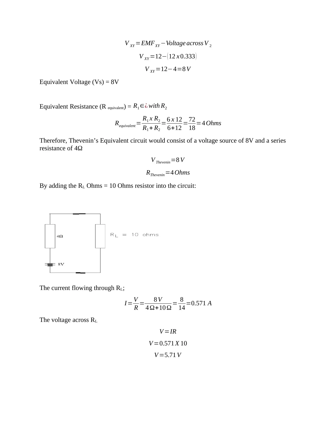
V XY =EMFXY −Voltage across V 2
V XY =12− ( 12 x 0.333 )
V XY =12−4=8 V
Equivalent Voltage (Vs) = 8V
Equivalent Resistance (R equivalent) = R1 ∈¿ with R2
Requivalent = R1 x R2
R1 + R2
=6 x 12
6+12 =72
18 =4 Ohms
Therefore, Thevenin’s Equivalent circuit would consist of a voltage source of 8V and a series
resistance of 4Ω
V Thevenin =8 V
RThevenin =4 Ohms
By adding the RL Ohms = 10 Ohms resistor into the circuit:
The current flowing through RL;
I = V
R = 8 V
4 Ω+10 Ω = 8
14 =0.571 A
The voltage across RL
V =IR
V =0.571 X 10
V =5.71 V
⊘ This is a preview!⊘
Do you want full access?
Subscribe today to unlock all pages.

Trusted by 1+ million students worldwide
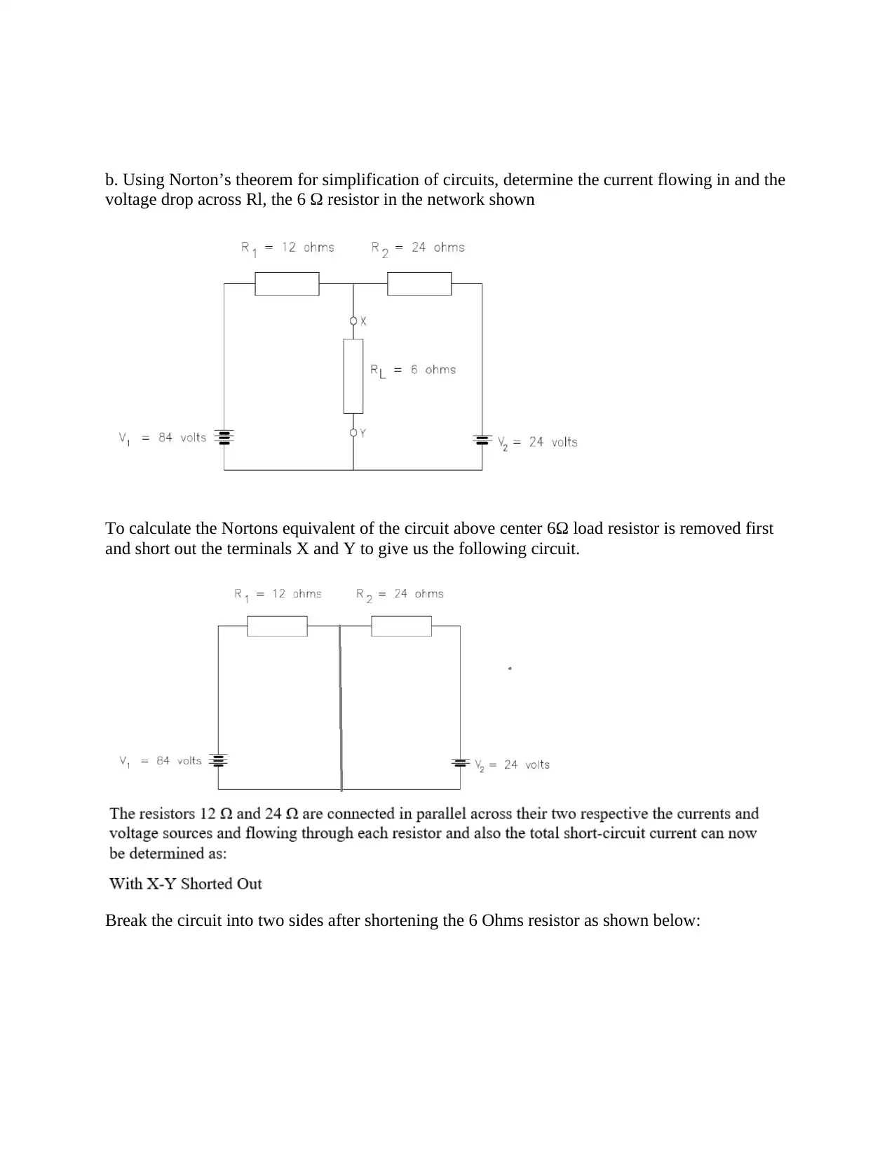
b. Using Norton’s theorem for simplification of circuits, determine the current flowing in and the
voltage drop across Rl, the 6 Ω resistor in the network shown
To calculate the Nortons equivalent of the circuit above center 6Ω load resistor is removed first
and short out the terminals X and Y to give us the following circuit.
Break the circuit into two sides after shortening the 6 Ohms resistor as shown below:
Paraphrase This Document
Need a fresh take? Get an instant paraphrase of this document with our AI Paraphraser
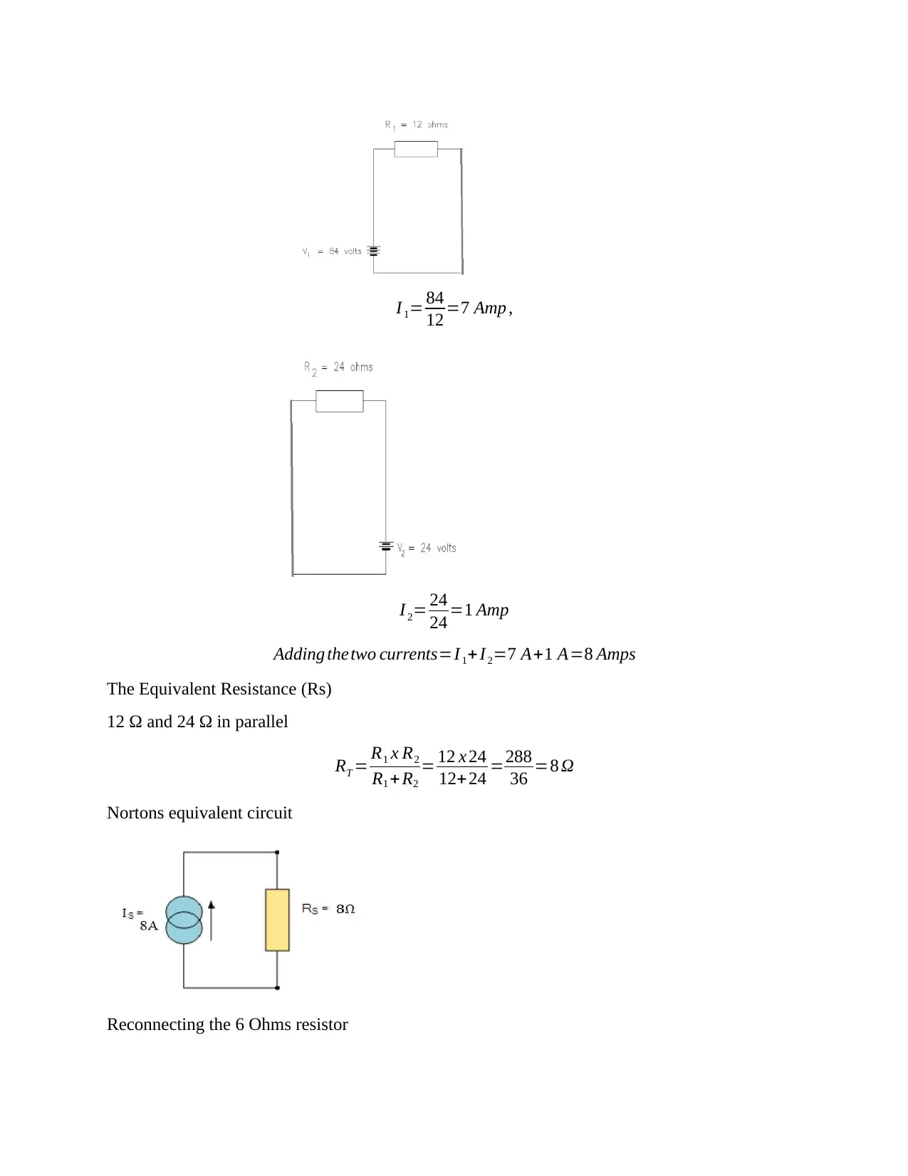
I 1= 84
12 =7 Amp ,
I 2= 24
24 =1 Amp
Adding thetwo currents=I 1+I 2=7 A+1 A=8 Amps
The Equivalent Resistance (Rs)
12 Ω and 24 Ω in parallel
RT = R1 x R2
R1 + R2
= 12 x 24
12+24 =288
36 =8 Ω
Nortons equivalent circuit
Reconnecting the 6 Ohms resistor
12 =7 Amp ,
I 2= 24
24 =1 Amp
Adding thetwo currents=I 1+I 2=7 A+1 A=8 Amps
The Equivalent Resistance (Rs)
12 Ω and 24 Ω in parallel
RT = R1 x R2
R1 + R2
= 12 x 24
12+24 =288
36 =8 Ω
Nortons equivalent circuit
Reconnecting the 6 Ohms resistor
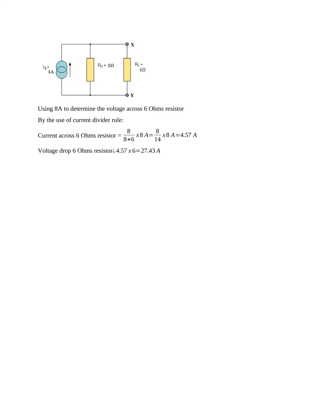
Using 8A to determine the voltage across 6 Ohms resistor
By the use of current divider rule:
Current across 6 Ohms resistor = 8
8+6 x 8 A= 8
14 x 8 A=4.57 A
Voltage drop 6 Ohms resistor¿ 4.57 x 6=27.43 A
By the use of current divider rule:
Current across 6 Ohms resistor = 8
8+6 x 8 A= 8
14 x 8 A=4.57 A
Voltage drop 6 Ohms resistor¿ 4.57 x 6=27.43 A
⊘ This is a preview!⊘
Do you want full access?
Subscribe today to unlock all pages.

Trusted by 1+ million students worldwide
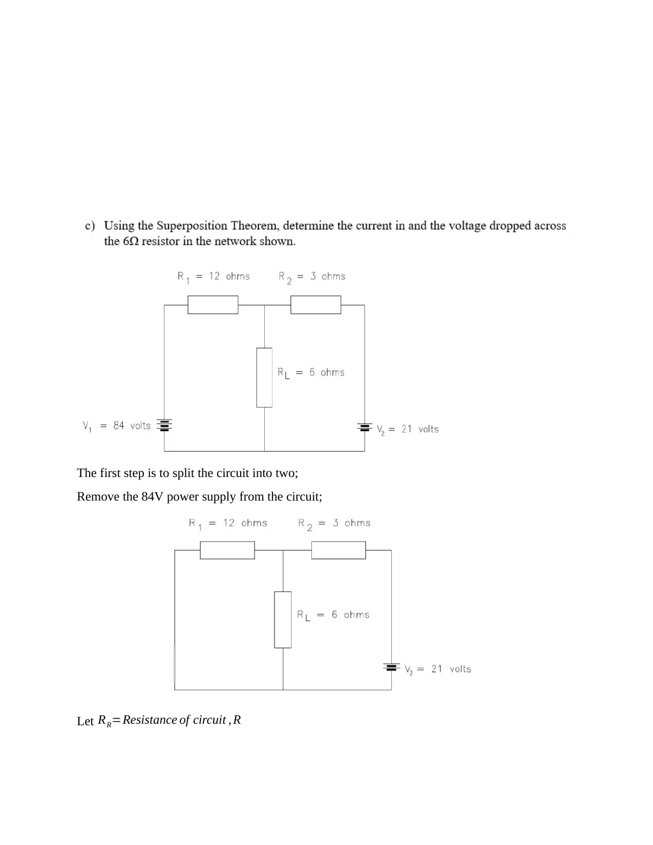
The first step is to split the circuit into two;
Remove the 84V power supply from the circuit;
Let RR=Resistance of circuit , R
Remove the 84V power supply from the circuit;
Let RR=Resistance of circuit , R
Paraphrase This Document
Need a fresh take? Get an instant paraphrase of this document with our AI Paraphraser
RR=R1 + RL x R3
RL+R3
=3+ 6 x 12
6+12 =3+ 72
18 =7 Ω
¿ I 2=21
7 =3 A
Calculating I 1∧I3
So V R=4 x 3=12V
I 1=12
12 =1 A
I 3= 12
6 =2 A
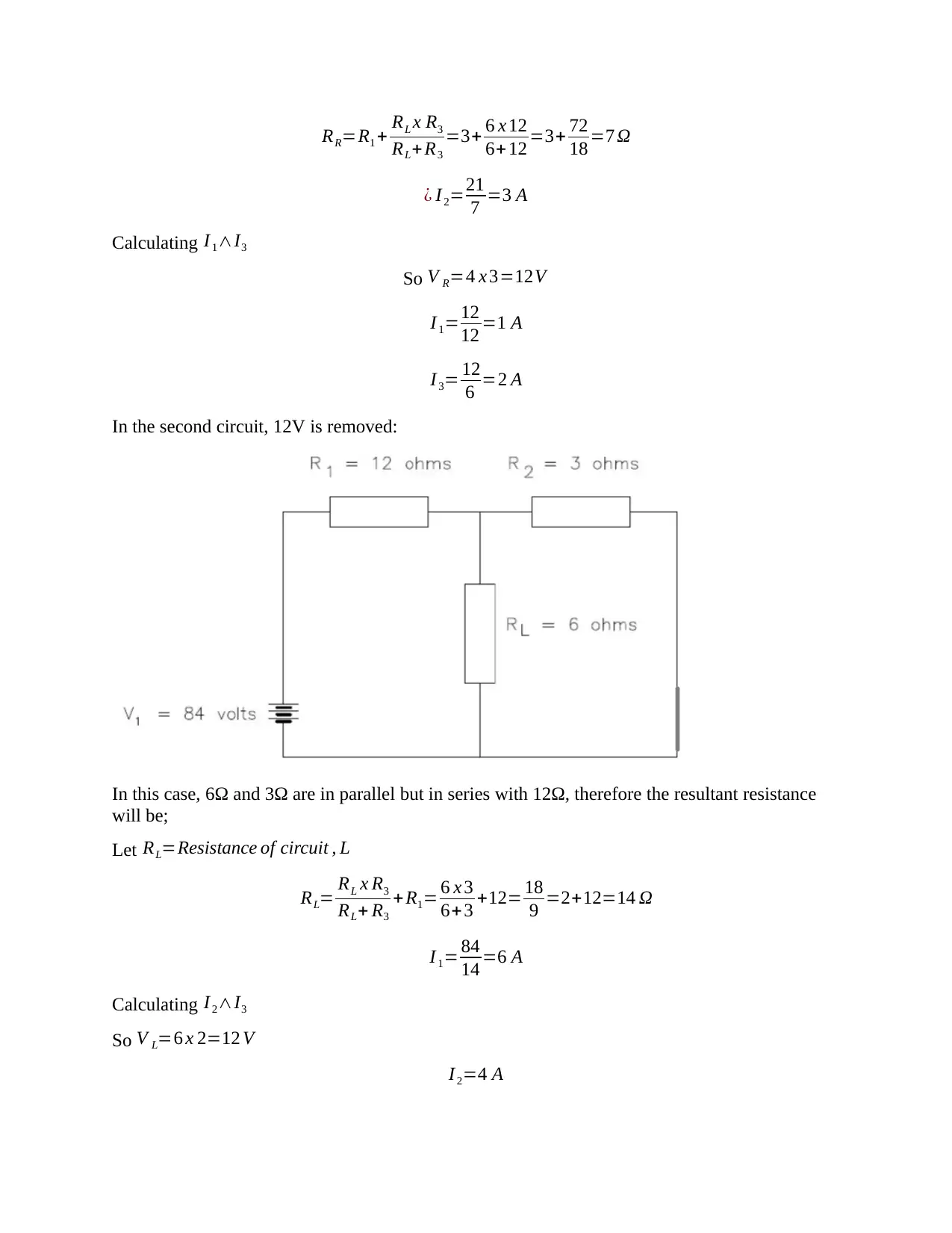
In the second circuit, 12V is removed:
In this case, 6Ω and 3Ω are in parallel but in series with 12Ω, therefore the resultant resistance
will be;
Let RL=Resistance of circuit , L
RL= RL x R3
RL+ R3
+ R1= 6 x 3
6+3 +12= 18
9 =2+12=14 Ω
I 1= 84
14 =6 A
Calculating I 2∧I3
So V L=6 x 2=12 V
I 2=4 A
I3=2 A
By reassembling the circuit;
From the Kirchhoff’s 1st Law: I 1+ I2 + I3 … … ..=0
I 1=6 A−1 A=5 A
I 2=4 A−3 A=1 A
I 3=2 A +2 A=4 A
Therefore, RL=4 A
Voltage across RL=4 x 6=24V
Task 3
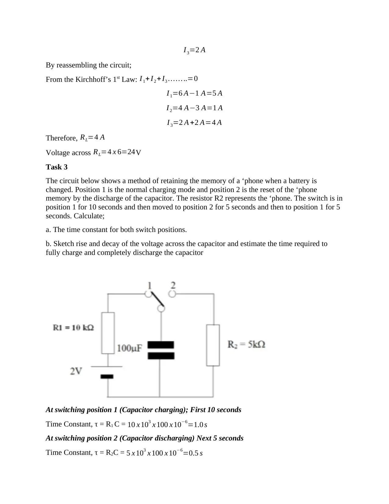
The circuit below shows a method of retaining the memory of a ‘phone when a battery is
changed. Position 1 is the normal charging mode and position 2 is the reset of the ‘phone
memory by the discharge of the capacitor. The resistor R2 represents the ‘phone. The switch is in
position 1 for 10 seconds and then moved to position 2 for 5 seconds and then to position 1 for 5
seconds. Calculate;
a. The time constant for both switch positions.
b. Sketch rise and decay of the voltage across the capacitor and estimate the time required to
fully charge and completely discharge the capacitor
At switching position 1 (Capacitor charging); First 10 seconds
Time Constant, τ = R1 C = 10 x 103 x 100 x 10−6=1.0 s
At switching position 2 (Capacitor discharging) Next 5 seconds
Time Constant, τ = R2C = 5 x 103 x 100 x 10−6=0.5 s
⊘ This is a preview!⊘
Do you want full access?
Subscribe today to unlock all pages.

Trusted by 1+ million students worldwide
1 out of 26
Related Documents
Your All-in-One AI-Powered Toolkit for Academic Success.
+13062052269
info@desklib.com
Available 24*7 on WhatsApp / Email
![[object Object]](/_next/static/media/star-bottom.7253800d.svg)
Unlock your academic potential
Copyright © 2020–2025 A2Z Services. All Rights Reserved. Developed and managed by ZUCOL.


