Electronics Digital Signal Processing Report 2022
VerifiedAdded on 2022/09/12
|7
|2257
|43
AI Summary
Contribute Materials
Your contribution can guide someone’s learning journey. Share your
documents today.
Electronics
Digital signal processing
Digital signal processing
Secure Best Marks with AI Grader
Need help grading? Try our AI Grader for instant feedback on your assignments.
Abstract:-
ECG signal is used to record the electrical activity of
the heart. These signals are of less amplitude and
affected by the noise, which includes the baseline
wander and power line interference. This study Aim
is to design the digital filters and implement them to
remove the unwanted noise. In this study, we create
filters such as Chebyshev filter design, Butterworth
Filter design, and Pole zero filter in the digital
domain. Responses of Different filters on the ECG
data are compared in terms of magnitude, stability,
and frequency response.
1. Introduction:-
The ECG (Electrocardiogram) is a significant bio-
electrical signal, which is used to diagnose various
diseases. The cardiologist used the ECG signals to
detect the cardiac system and heart conditions. ECG
is a graphical recording of the signal which displays
the time-varying voltage, which formed by the
myocardium throughout the cardiac cycle [4] .
During the diagnosis Cardiologist also looks for the
heart rate. In a digital signal, processing filters play
an essential role in removing the noise and unwanted
signal and extract the valuable information within
the specified frequency range. Many filters are used
to remove the baseline drift of the ECG signal. In
this study, we are used various types of digital filter
techniques to remove the noise. Digital Filters such
as Butterworth, pole-zero filter and Chebyshev are
used for the processing of the ECG signals [1].
Butterworth digital filter is used in an area in which
maximum passband flatness is needed. However,
other Chebyshev digital filter is used to optimize the
steeper roll-off. So these filters pass the ECG signal
without the attenuation [10]. Therefore these filters
are required for the conditioning of the analog signal
where distortion of signal is not needed.
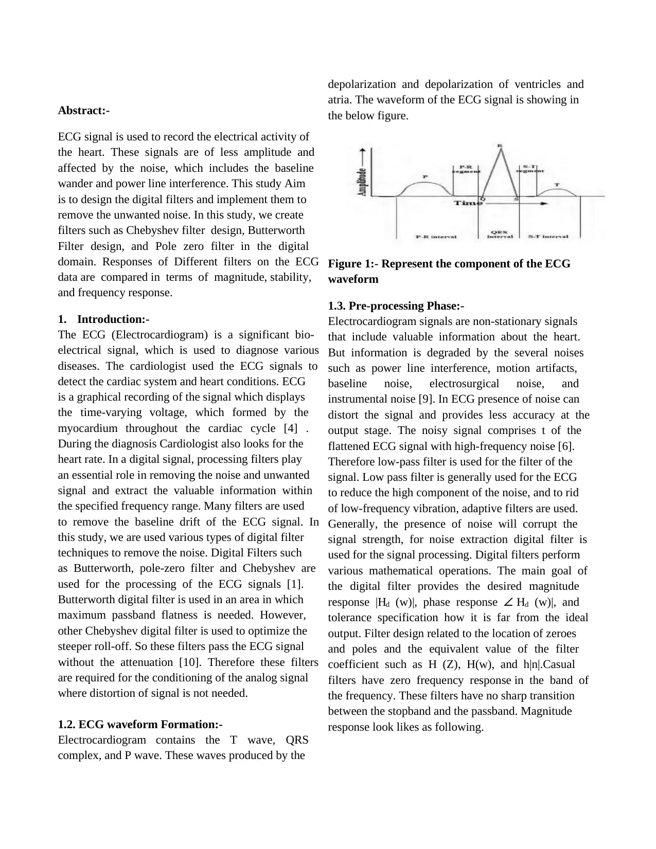
1.2. ECG waveform Formation:-
Electrocardiogram contains the T wave, QRS
complex, and P wave. These waves produced by the
depolarization and depolarization of ventricles and
atria. The waveform of the ECG signal is showing in
the below figure.
Figure 1:- Represent the component of the ECG
waveform
1.3. Pre-processing Phase:-
Electrocardiogram signals are non-stationary signals
that include valuable information about the heart.
But information is degraded by the several noises
such as power line interference, motion artifacts,
baseline noise, electrosurgical noise, and
instrumental noise [9]. In ECG presence of noise can
distort the signal and provides less accuracy at the
output stage. The noisy signal comprises t of the
flattened ECG signal with high-frequency noise [6].
Therefore low-pass filter is used for the filter of the
signal. Low pass filter is generally used for the ECG
to reduce the high component of the noise, and to rid
of low-frequency vibration, adaptive filters are used.
Generally, the presence of noise will corrupt the
signal strength, for noise extraction digital filter is
used for the signal processing. Digital filters perform
various mathematical operations. The main goal of
the digital filter provides the desired magnitude
response |Hd (w)|, phase response ∠ Hd (w)|, and
tolerance specification how it is far from the ideal
output. Filter design related to the location of zeroes
and poles and the equivalent value of the filter
coefficient such as H (Z), H(w), and h|n|.Casual
filters have zero frequency response in the band of
the frequency. These filters have no sharp transition
between the stopband and the passband. Magnitude
response look likes as following.
ECG signal is used to record the electrical activity of
the heart. These signals are of less amplitude and
affected by the noise, which includes the baseline
wander and power line interference. This study Aim
is to design the digital filters and implement them to
remove the unwanted noise. In this study, we create
filters such as Chebyshev filter design, Butterworth
Filter design, and Pole zero filter in the digital
domain. Responses of Different filters on the ECG
data are compared in terms of magnitude, stability,
and frequency response.
1. Introduction:-
The ECG (Electrocardiogram) is a significant bio-
electrical signal, which is used to diagnose various
diseases. The cardiologist used the ECG signals to
detect the cardiac system and heart conditions. ECG
is a graphical recording of the signal which displays
the time-varying voltage, which formed by the
myocardium throughout the cardiac cycle [4] .
During the diagnosis Cardiologist also looks for the
heart rate. In a digital signal, processing filters play
an essential role in removing the noise and unwanted
signal and extract the valuable information within
the specified frequency range. Many filters are used
to remove the baseline drift of the ECG signal. In
this study, we are used various types of digital filter
techniques to remove the noise. Digital Filters such
as Butterworth, pole-zero filter and Chebyshev are
used for the processing of the ECG signals [1].
Butterworth digital filter is used in an area in which
maximum passband flatness is needed. However,
other Chebyshev digital filter is used to optimize the
steeper roll-off. So these filters pass the ECG signal
without the attenuation [10]. Therefore these filters
are required for the conditioning of the analog signal
where distortion of signal is not needed.
1.2. ECG waveform Formation:-
Electrocardiogram contains the T wave, QRS
complex, and P wave. These waves produced by the
depolarization and depolarization of ventricles and
atria. The waveform of the ECG signal is showing in
the below figure.
Figure 1:- Represent the component of the ECG
waveform
1.3. Pre-processing Phase:-
Electrocardiogram signals are non-stationary signals
that include valuable information about the heart.
But information is degraded by the several noises
such as power line interference, motion artifacts,
baseline noise, electrosurgical noise, and
instrumental noise [9]. In ECG presence of noise can
distort the signal and provides less accuracy at the
output stage. The noisy signal comprises t of the
flattened ECG signal with high-frequency noise [6].
Therefore low-pass filter is used for the filter of the
signal. Low pass filter is generally used for the ECG
to reduce the high component of the noise, and to rid
of low-frequency vibration, adaptive filters are used.
Generally, the presence of noise will corrupt the
signal strength, for noise extraction digital filter is
used for the signal processing. Digital filters perform
various mathematical operations. The main goal of
the digital filter provides the desired magnitude
response |Hd (w)|, phase response ∠ Hd (w)|, and
tolerance specification how it is far from the ideal
output. Filter design related to the location of zeroes
and poles and the equivalent value of the filter
coefficient such as H (Z), H(w), and h|n|.Casual
filters have zero frequency response in the band of
the frequency. These filters have no sharp transition
between the stopband and the passband. Magnitude
response look likes as following.
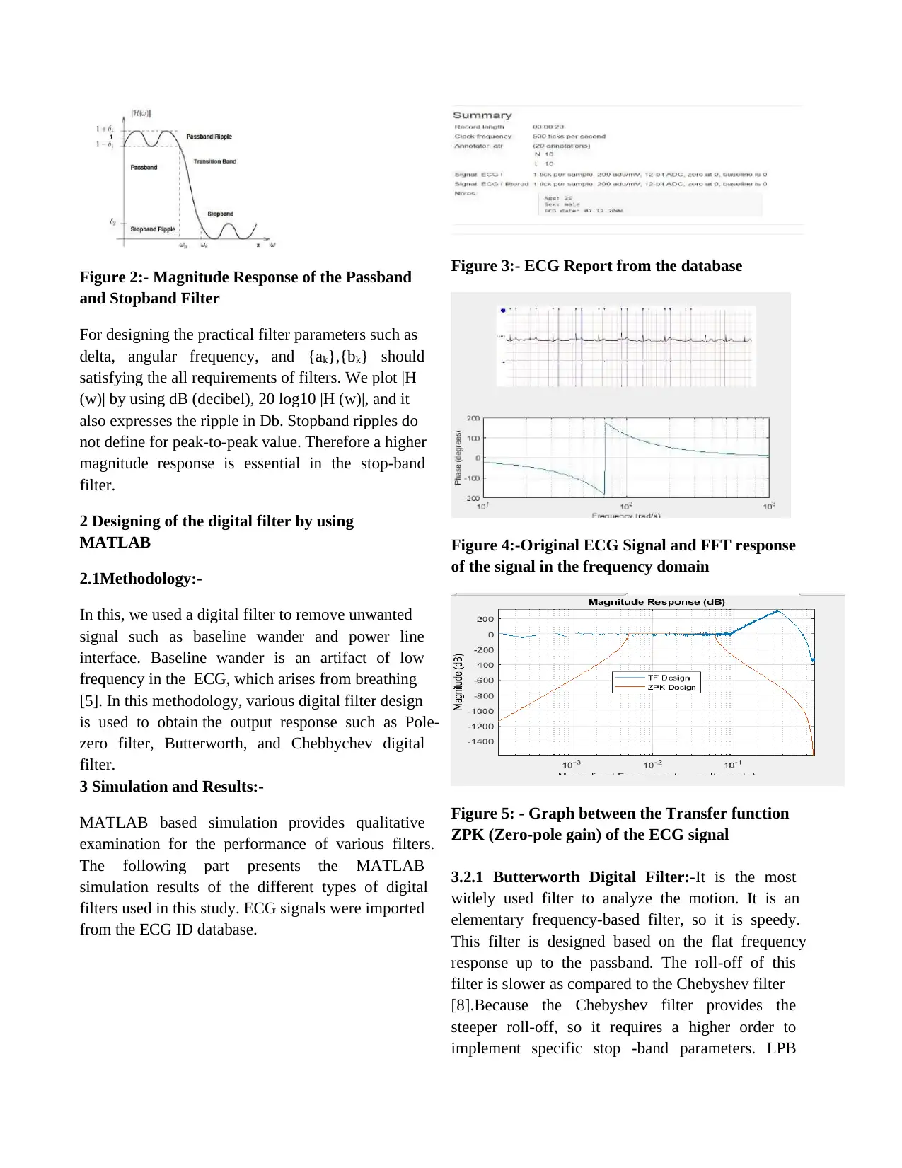
Figure 2:- Magnitude Response of the Passband
and Stopband Filter
For designing the practical filter parameters such as
delta, angular frequency, and {ak},{bk} should
satisfying the all requirements of filters. We plot |H
(w)| by using dB (decibel), 20 log10 |H (w)|, and it
also expresses the ripple in Db. Stopband ripples do
not define for peak-to-peak value. Therefore a higher
magnitude response is essential in the stop-band
filter.
2 Designing of the digital filter by using
MATLAB
2.1Methodology:-
In this, we used a digital filter to remove unwanted
signal such as baseline wander and power line
interface. Baseline wander is an artifact of low
frequency in the ECG, which arises from breathing
[5]. In this methodology, various digital filter design
is used to obtain the output response such as Pole-
zero filter, Butterworth, and Chebbychev digital
filter.
3 Simulation and Results:-
MATLAB based simulation provides qualitative
examination for the performance of various filters.
The following part presents the MATLAB
simulation results of the different types of digital
filters used in this study. ECG signals were imported
from the ECG ID database.
Figure 3:- ECG Report from the database
Figure 4:-Original ECG Signal and FFT response
of the signal in the frequency domain
Figure 5: - Graph between the Transfer function
ZPK (Zero-pole gain) of the ECG signal
3.2.1 Butterworth Digital Filter:-It is the most
widely used filter to analyze the motion. It is an
elementary frequency-based filter, so it is speedy.
This filter is designed based on the flat frequency
response up to the passband. The roll-off of this
filter is slower as compared to the Chebyshev filter
[8].Because the Chebyshev filter provides the
steeper roll-off, so it requires a higher order to
implement specific stop -band parameters. LPB
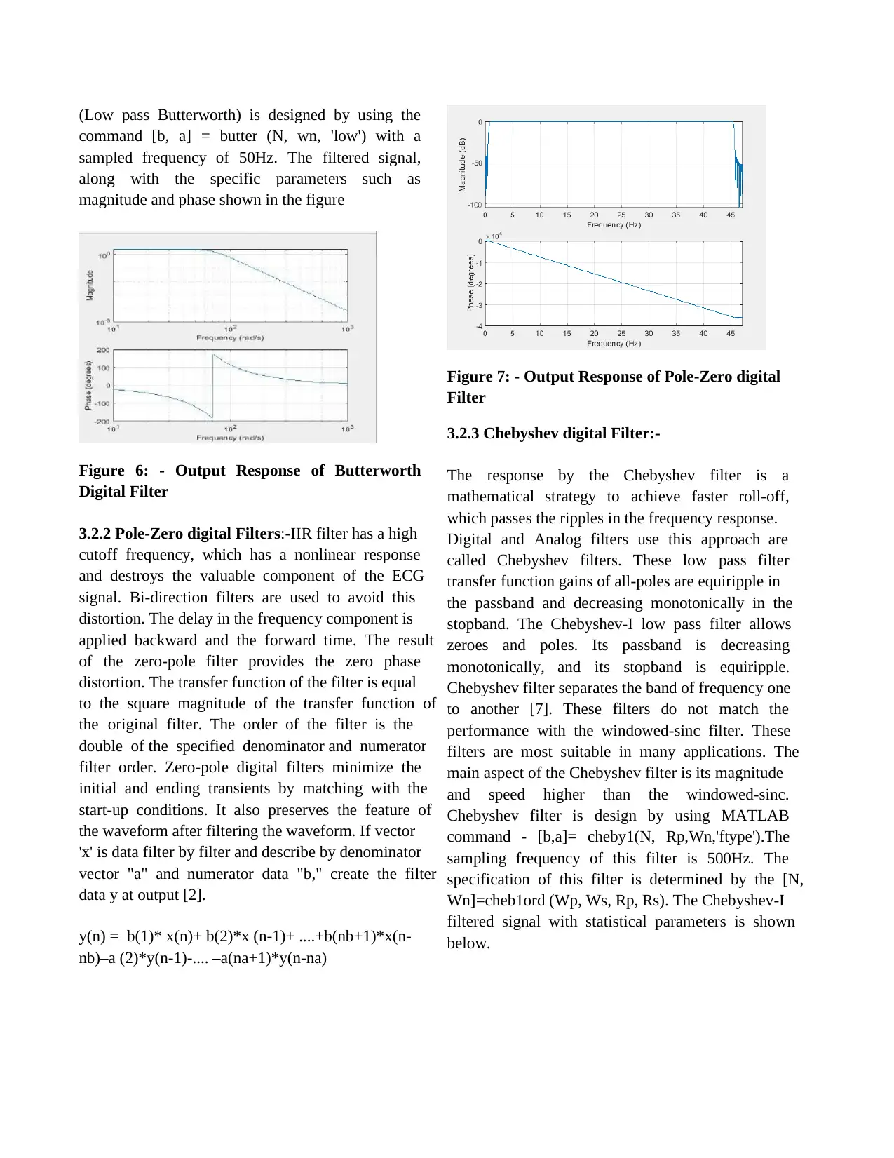
(Low pass Butterworth) is designed by using the
command [b, a] = butter (N, wn, 'low') with a
sampled frequency of 50Hz. The filtered signal,
along with the specific parameters such as
magnitude and phase shown in the figure
Figure 6: - Output Response of Butterworth
Digital Filter
3.2.2 Pole-Zero digital Filters:-IIR filter has a high
cutoff frequency, which has a nonlinear response
and destroys the valuable component of the ECG
signal. Bi-direction filters are used to avoid this
distortion. The delay in the frequency component is
applied backward and the forward time. The result
of the zero-pole filter provides the zero phase
distortion. The transfer function of the filter is equal
to the square magnitude of the transfer function of
the original filter. The order of the filter is the
double of the specified denominator and numerator
filter order. Zero-pole digital filters minimize the
initial and ending transients by matching with the
start-up conditions. It also preserves the feature of
the waveform after filtering the waveform. If vector
'x' is data filter by filter and describe by denominator
vector "a" and numerator data "b," create the filter
data y at output [2].
y(n) = b(1)* x(n)+ b(2)*x (n-1)+ ....+b(nb+1)*x(n-
nb)–a (2)*y(n-1)-.... –a(na+1)*y(n-na)
Figure 7: - Output Response of Pole-Zero digital
Filter
3.2.3 Chebyshev digital Filter:-
The response by the Chebyshev filter is a
mathematical strategy to achieve faster roll-off,
which passes the ripples in the frequency response.
Digital and Analog filters use this approach are
called Chebyshev filters. These low pass filter
transfer function gains of all-poles are equiripple in
the passband and decreasing monotonically in the
stopband. The Chebyshev-I low pass filter allows
zeroes and poles. Its passband is decreasing
monotonically, and its stopband is equiripple.
Chebyshev filter separates the band of frequency one
to another [7]. These filters do not match the
performance with the windowed-sinc filter. These
filters are most suitable in many applications. The
main aspect of the Chebyshev filter is its magnitude
and speed higher than the windowed-sinc.
Chebyshev filter is design by using MATLAB
command - [b,a]= cheby1(N, Rp,Wn,'ftype').The
sampling frequency of this filter is 500Hz. The
specification of this filter is determined by the [N,
Wn]=cheb1ord (Wp, Ws, Rp, Rs). The Chebyshev-I
filtered signal with statistical parameters is shown
below.
Secure Best Marks with AI Grader
Need help grading? Try our AI Grader for instant feedback on your assignments.
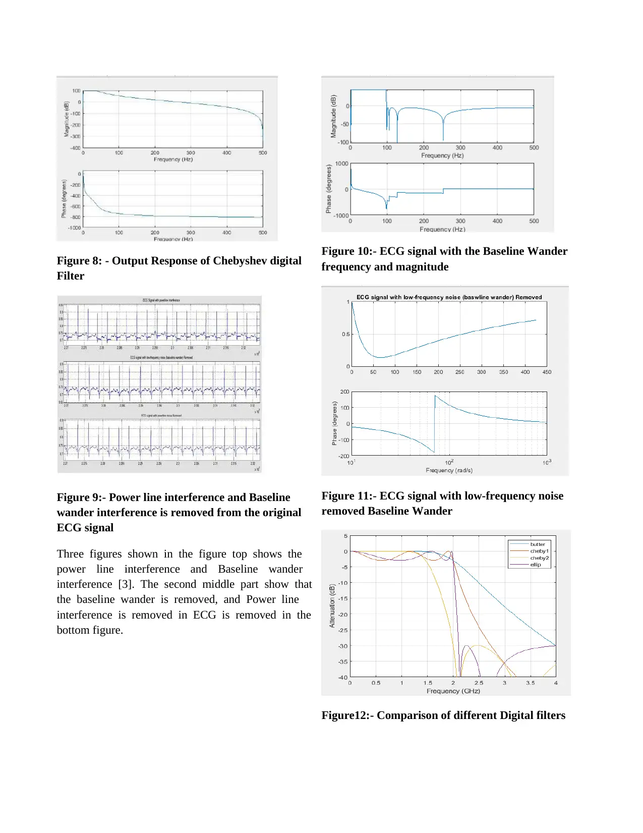
Figure 8: - Output Response of Chebyshev digital
Filter
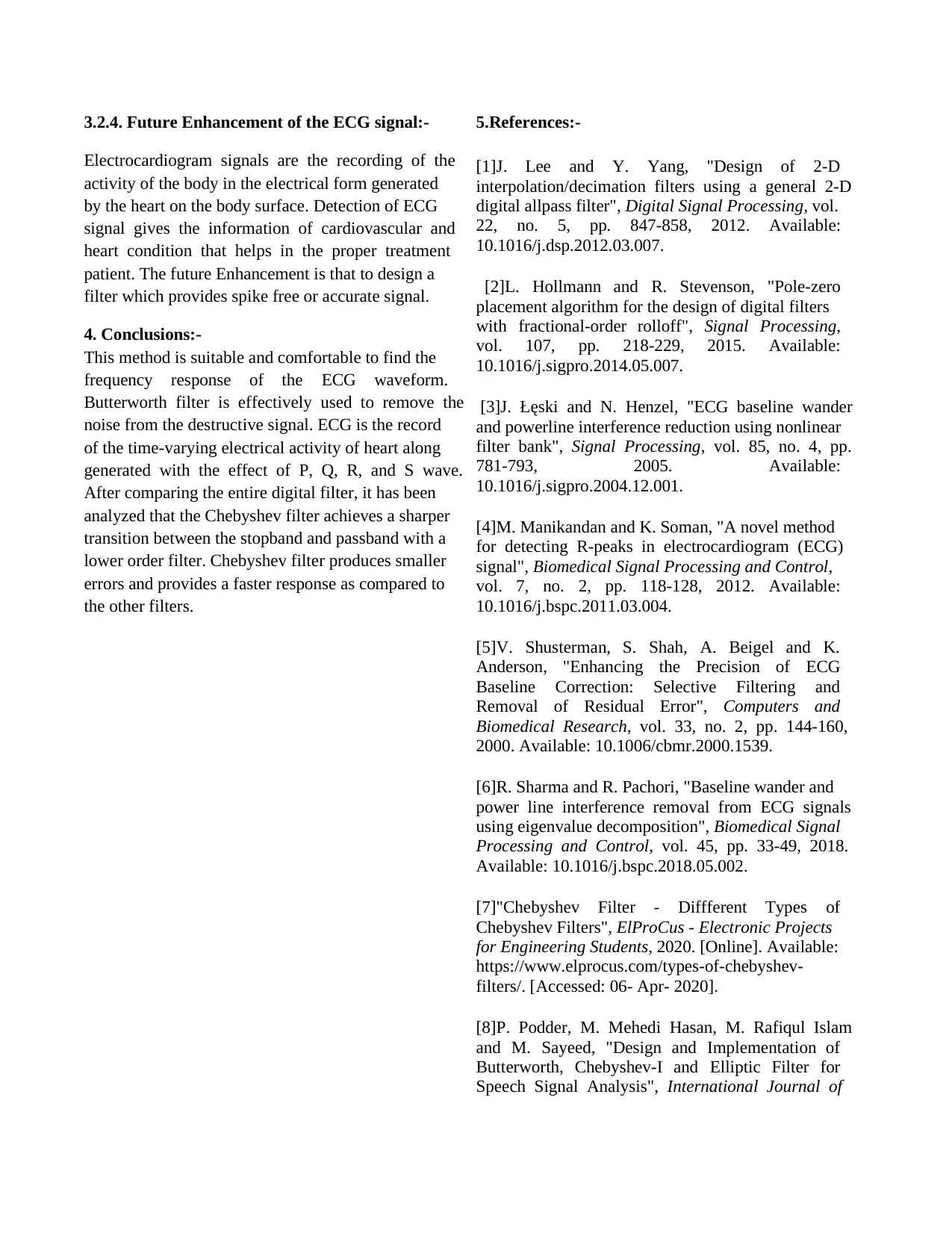
Figure 9:- Power line interference and Baseline
wander interference is removed from the original
ECG signal
Three figures shown in the figure top shows the
power line interference and Baseline wander
interference [3]. The second middle part show that
the baseline wander is removed, and Power line
interference is removed in ECG is removed in the
bottom figure.
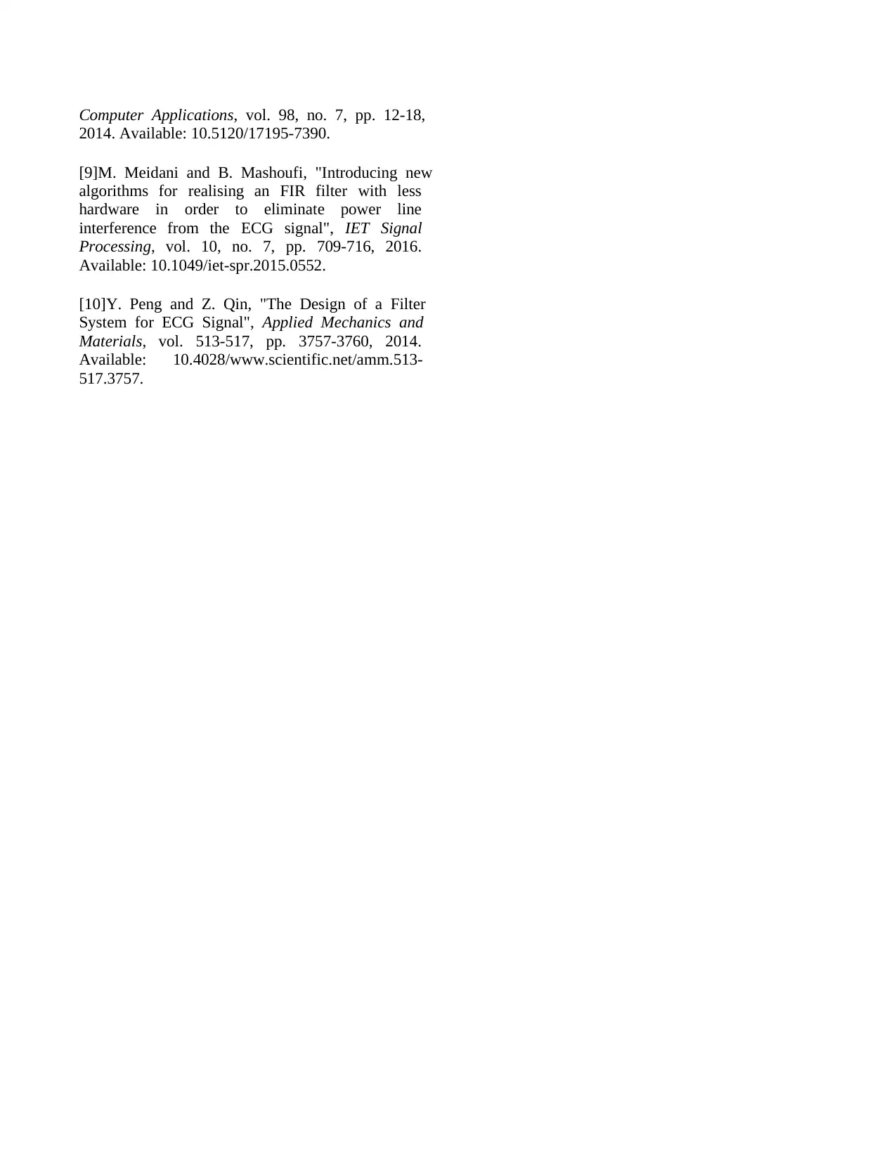
Figure 10:- ECG signal with the Baseline Wander
frequency and magnitude
Figure 11:- ECG signal with low-frequency noise
removed Baseline Wander
Figure12:- Comparison of different Digital filters
Filter
Figure 9:- Power line interference and Baseline
wander interference is removed from the original
ECG signal
Three figures shown in the figure top shows the
power line interference and Baseline wander
interference [3]. The second middle part show that
the baseline wander is removed, and Power line
interference is removed in ECG is removed in the
bottom figure.
Figure 10:- ECG signal with the Baseline Wander
frequency and magnitude
Figure 11:- ECG signal with low-frequency noise
removed Baseline Wander
Figure12:- Comparison of different Digital filters
3.2.4. Future Enhancement of the ECG signal:-
Electrocardiogram signals are the recording of the
activity of the body in the electrical form generated
by the heart on the body surface. Detection of ECG
signal gives the information of cardiovascular and
heart condition that helps in the proper treatment
patient. The future Enhancement is that to design a
filter which provides spike free or accurate signal.
4. Conclusions:-
This method is suitable and comfortable to find the
frequency response of the ECG waveform.
Butterworth filter is effectively used to remove the
noise from the destructive signal. ECG is the record
of the time-varying electrical activity of heart along
generated with the effect of P, Q, R, and S wave.
After comparing the entire digital filter, it has been
analyzed that the Chebyshev filter achieves a sharper
transition between the stopband and passband with a
lower order filter. Chebyshev filter produces smaller
errors and provides a faster response as compared to
the other filters.
5.References:-
[1]J. Lee and Y. Yang, "Design of 2-D
interpolation/decimation filters using a general 2-D
digital allpass filter", Digital Signal Processing, vol.
22, no. 5, pp. 847-858, 2012. Available:
10.1016/j.dsp.2012.03.007.
[2]L. Hollmann and R. Stevenson, "Pole-zero
placement algorithm for the design of digital filters
with fractional-order rolloff", Signal Processing,
vol. 107, pp. 218-229, 2015. Available:
10.1016/j.sigpro.2014.05.007.
[3]J. Łęski and N. Henzel, "ECG baseline wander
and powerline interference reduction using nonlinear
filter bank", Signal Processing, vol. 85, no. 4, pp.
781-793, 2005. Available:
10.1016/j.sigpro.2004.12.001.
[4]M. Manikandan and K. Soman, "A novel method
for detecting R-peaks in electrocardiogram (ECG)
signal", Biomedical Signal Processing and Control,
vol. 7, no. 2, pp. 118-128, 2012. Available:
10.1016/j.bspc.2011.03.004.
[5]V. Shusterman, S. Shah, A. Beigel and K.
Anderson, "Enhancing the Precision of ECG
Baseline Correction: Selective Filtering and
Removal of Residual Error", Computers and
Biomedical Research, vol. 33, no. 2, pp. 144-160,
2000. Available: 10.1006/cbmr.2000.1539.
[6]R. Sharma and R. Pachori, "Baseline wander and
power line interference removal from ECG signals
using eigenvalue decomposition", Biomedical Signal
Processing and Control, vol. 45, pp. 33-49, 2018.
Available: 10.1016/j.bspc.2018.05.002.
[7]"Chebyshev Filter - Diffferent Types of
Chebyshev Filters", ElProCus - Electronic Projects
for Engineering Students, 2020. [Online]. Available:
https://www.elprocus.com/types-of-chebyshev-
filters/. [Accessed: 06- Apr- 2020].
[8]P. Podder, M. Mehedi Hasan, M. Rafiqul Islam
and M. Sayeed, "Design and Implementation of
Butterworth, Chebyshev-I and Elliptic Filter for
Speech Signal Analysis", International Journal of
Computer Applications, vol. 98, no. 7, pp. 12-18,
2014. Available: 10.5120/17195-7390.
[9]M. Meidani and B. Mashoufi, "Introducing new
algorithms for realising an FIR filter with less
hardware in order to eliminate power line
interference from the ECG signal", IET Signal
Processing, vol. 10, no. 7, pp. 709-716, 2016.
Available: 10.1049/iet-spr.2015.0552.
[10]Y. Peng and Z. Qin, "The Design of a Filter
System for ECG Signal", Applied Mechanics and
Materials, vol. 513-517, pp. 3757-3760, 2014.
Available: 10.4028/www.scientific.net/amm.513-
517.3757.
1 out of 7
Related Documents


Your All-in-One AI-Powered Toolkit for Academic Success.
+13062052269
info@desklib.com
Available 24*7 on WhatsApp / Email
![[object Object]](/_next/static/media/star-bottom.7253800d.svg)
Unlock your academic potential
© 2024 | Zucol Services PVT LTD | All rights reserved.