Evacuated Tube Solar Collector
VerifiedAdded on 2023/06/09
|15
|4003
|382
AI Summary
This article provides an overview of evacuated tube solar collectors, including their components, mechanics of operation, and production and operational costs. It discusses the two main configurations of heat pipe and direct flow, as well as technical details and climatic effects on ECT. The article is relevant for students studying solar thermal technologies and renewable energy.
Contribute Materials
Your contribution can guide someone’s learning journey. Share your
documents today.

Running Head: Evacuated Tube Solar Collector 1
EVACUATED TUBE SOLAR COLLECTOR
Student’s name
University affiliation
EVACUATED TUBE SOLAR COLLECTOR
Student’s name
University affiliation
Secure Best Marks with AI Grader
Need help grading? Try our AI Grader for instant feedback on your assignments.
Executive Summary
Before modern solar technologies were formed, people still relied on the sun to draw
energy mainly for heating their homes. With time, the methods being used for drawing energy
from the sun have increased immensely. Solar thermal is the name used to refer to these
methods, they require collectors to operate unlike the previously known photovoltaic technology.
Evacuated solar collector tubes are being put to use globally due to their great working
temperatures and great thermal efficiencies when compared to other type of solar collector
technologies. Loss of heat by convection and conduction is significantly minimized by the use of
the vacuum in between the tube collector and absorber. An evacuated tube solar collector is able
to achieve temperatures of between 77˚C to 177˚ C and usually works efficiently under the right
conditions. The pricing of its cost per unit is higher than its flat plate counterpart. They are best
used in industrial and commercial heating applications as well as refrigeration cycle regeneration
(cooling applications). Domestic application can benefit those staying in cloudy areas by
replacing the flat plate collectors that are cheaper but inefficient. These collectors are made up of
metallic plates that are flat and black coated to increase rate of heat absorption; a polycarbonate
cover or thin, clear glass is used to help capture the heat; liquid filled pipes (commonly a mixture
of glycol antifreeze and water) (Duffie & Beckman, 2013). The heat is captured by the collectors
and transferred to the pipes where the liquid can be heated then transferred to the building for
heating purposes. This paper will focus on the evacuated solar tube collector in the following
sections by giving a brief overview of the system, its key mechanics of operations, the issues to
do with the materials used in design and finally how the climate affects the overall working of
this technology.
Table of Contents
Executive Summary.....................................................................................................................................2
1. Introduction to Evacuated Solar Tube Collector..................................................................................4
2. Heat Pipe Evacuated Tube Collectors..................................................................................................5
3. Direct Flow Evacuated Tube Collector.................................................................................................6
4. Production and operational costs.........................................................................................................7
Component technical details......................................................................................................................10
Outer Glass Tube...................................................................................................................................10
Inner Glass Tube....................................................................................................................................11
Aluminum Fin.......................................................................................................................................11
U-Copper Pipe.......................................................................................................................................11
Climatic Effect on ECT................................................................................................................................12
References.................................................................................................................................................13
Table of Figures
Figure 1-1 Example of Evacuated Solar Tube Collector...............................................................................4
Figure 2-1 Heat Pipe Evacuated Solar Tube Collector..................................................................................6
Figure 3-1 Direct Flow Evacuated Tube.......................................................................................................7
Figure 4-1 Costs in percentages of Production of ECT.................................................................................8
Figure 4-2 Graph of Cost vs. Units per day..................................................................................................8
Figure 4-3 Graph showing increasing production with reduced unit cost...................................................9
1. Introduction to Evacuated Solar Tube Collector
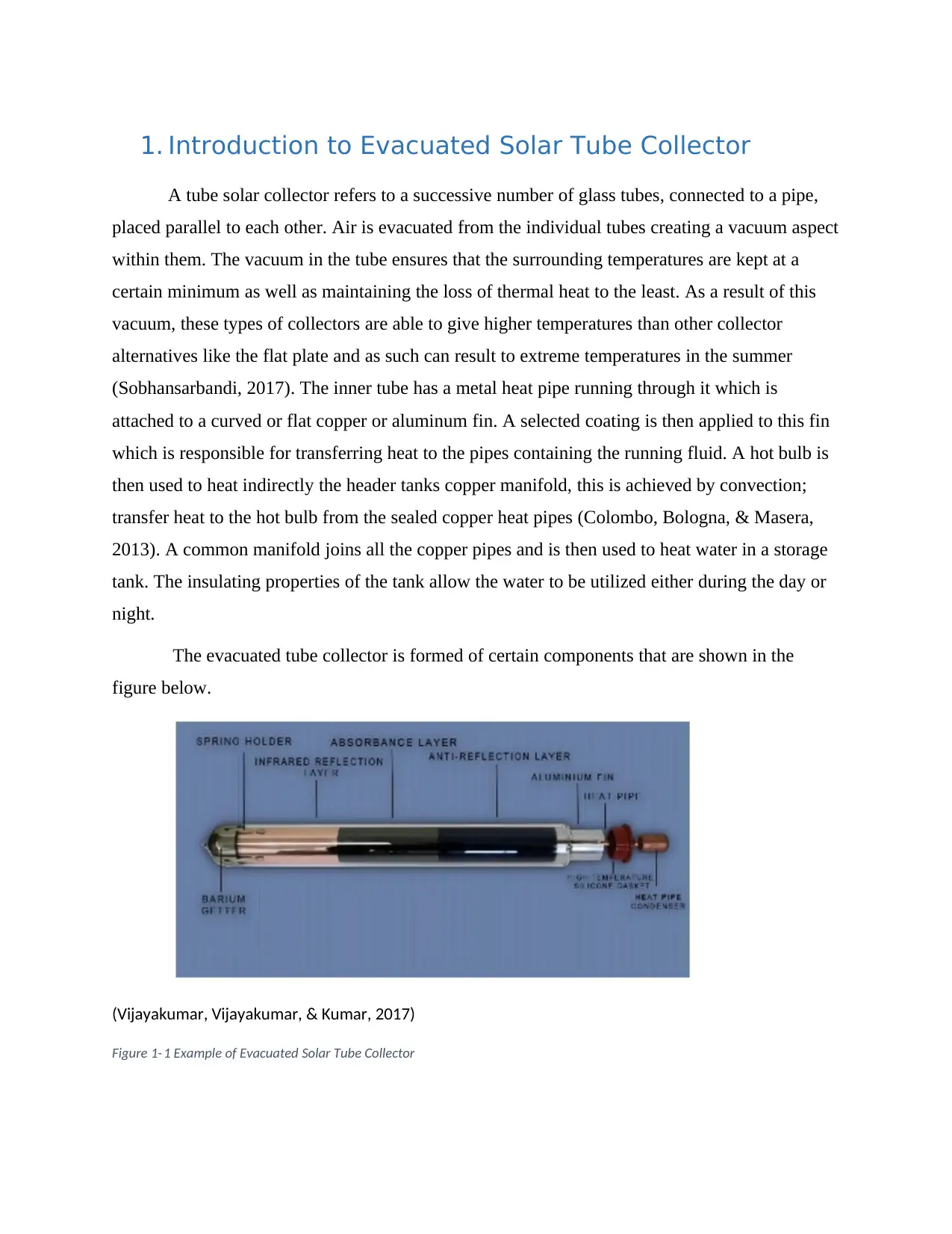
A tube solar collector refers to a successive number of glass tubes, connected to a pipe,
placed parallel to each other. Air is evacuated from the individual tubes creating a vacuum aspect
within them. The vacuum in the tube ensures that the surrounding temperatures are kept at a
certain minimum as well as maintaining the loss of thermal heat to the least. As a result of this
vacuum, these types of collectors are able to give higher temperatures than other collector
alternatives like the flat plate and as such can result to extreme temperatures in the summer
(Sobhansarbandi, 2017). The inner tube has a metal heat pipe running through it which is
attached to a curved or flat copper or aluminum fin. A selected coating is then applied to this fin
which is responsible for transferring heat to the pipes containing the running fluid. A hot bulb is
then used to heat indirectly the header tanks copper manifold, this is achieved by convection;
transfer heat to the hot bulb from the sealed copper heat pipes (Colombo, Bologna, & Masera,
2013). A common manifold joins all the copper pipes and is then used to heat water in a storage
tank. The insulating properties of the tank allow the water to be utilized either during the day or
night.
The evacuated tube collector is formed of certain components that are shown in the
figure below.
(Vijayakumar, Vijayakumar, & Kumar, 2017)
Figure 1- 1 Example of Evacuated Solar Tube Collector
Secure Best Marks with AI Grader
Need help grading? Try our AI Grader for instant feedback on your assignments.
Energy from the sun is absorbed by the evacuated tube. Since energy needs to be retained
for longer the insulating properties of the vacuum tube come in handy. The aspect of solar
absorption in this technology however dictates the design that can be best use. For instance, the
twin glass tube which is a common type of evacuated tube collector technology has an outer tube
that is able to withstand severe environmental hazards such as hailstones. The inner tube is
however coated with an excellent solar absorber in this case (Al-N/Al). A barium getter is
usually used in the design to maintain the vacuum. A pure layer of barium is formed when the
evacuated tube is subjected to high temperatures during the design process. The work of the
getter is to absorb the gases ousted from the tube during the operation and storage which include:
hydrogen, water, nitrogen, carbon (IV) oxide and carbon (ii) oxide.
Over the years the most commonly used material used in the absorbance layer was copper
but due to the price changes it made it hard to manufacture tube collectors with copper.
Although it is still being used, engineers decided to use alternative like aluminum that is a
readily available conductor. Collectors with aluminum reduce the cost of obtaining a collector
with Cu-Cu almost by half. Another way of reducing cases of poor conductivity is by the use of
heat pipes in the design. They are better than Cu and Al in terms of thermal conductivity.
Between hot and cold interfaces they experience lower temperature differences. The working
fluid plays an important role in the efficiency of a collector to convert heat to energy without any
losses. Researchers are now insisting on using Nano fluids, this is because miniaturized
technologies are coming up and clogging can of the tubes can be a problem when the
conventional fluids are used.
There are two main tube configurations that can be incorporated in the design of an
evacuated solar collector. These configurations are responsible for the difference in efficiency in
such systems (show how the fluid will flow in the system). They include; heat pipe or direct
flow, double wall tube, single wall tube (Kitcher, 2012).
2. Heat Pipe Evacuated Tube Collectors
This contains a copper heat pipe, attached to a reflector plate capable of absorbing heat
that is usually sealed and placed in the vacuumed tube. Copper material is used to increase the
efficiency of the collector during cold weather. Even though the heat pipe is evacuated, it still
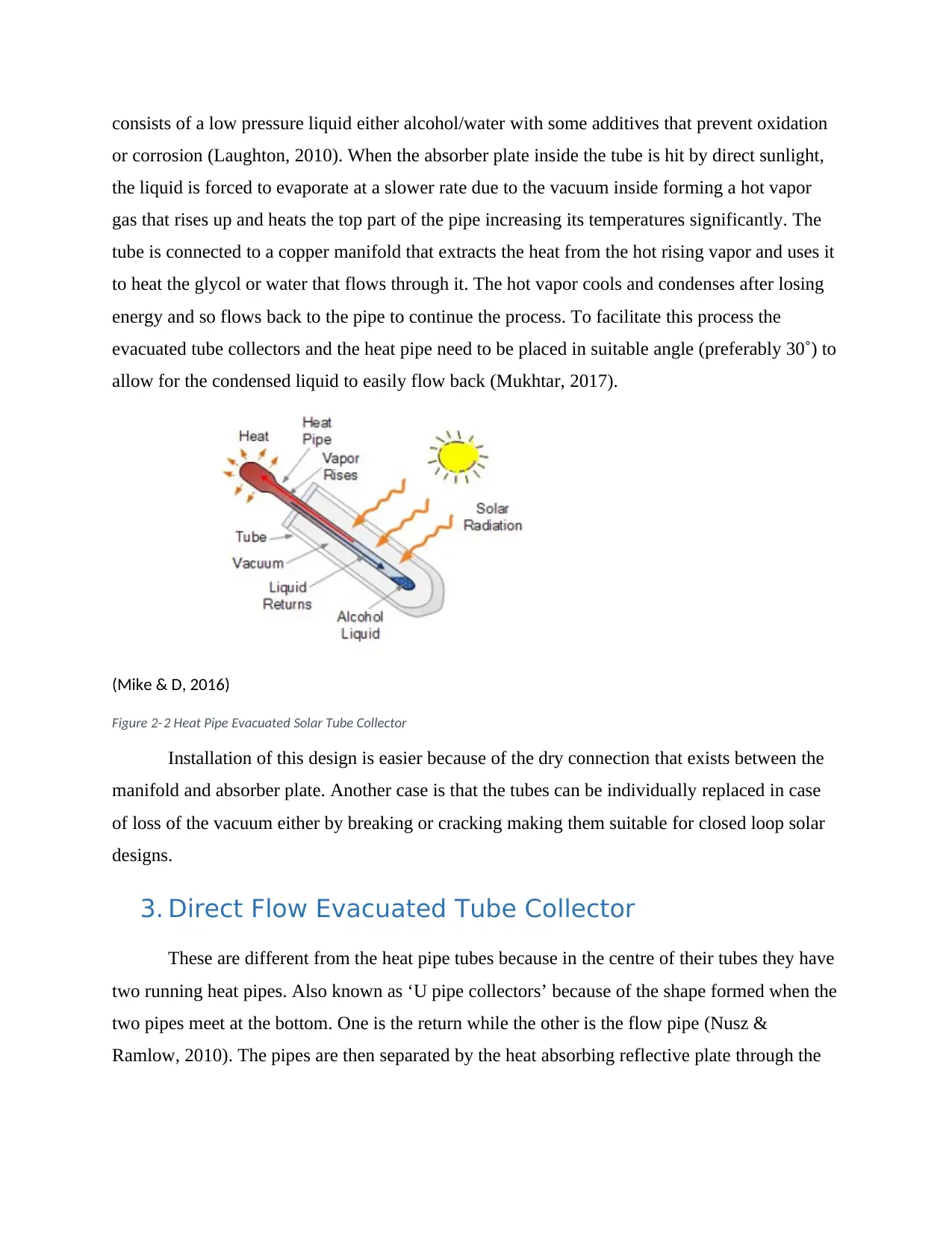
consists of a low pressure liquid either alcohol/water with some additives that prevent oxidation
or corrosion (Laughton, 2010). When the absorber plate inside the tube is hit by direct sunlight,
the liquid is forced to evaporate at a slower rate due to the vacuum inside forming a hot vapor
gas that rises up and heats the top part of the pipe increasing its temperatures significantly. The
tube is connected to a copper manifold that extracts the heat from the hot rising vapor and uses it
to heat the glycol or water that flows through it. The hot vapor cools and condenses after losing
energy and so flows back to the pipe to continue the process. To facilitate this process the
evacuated tube collectors and the heat pipe need to be placed in suitable angle (preferably 30˚) to
allow for the condensed liquid to easily flow back (Mukhtar, 2017).
(Mike & D, 2016)
Figure 2- 2 Heat Pipe Evacuated Solar Tube Collector
Installation of this design is easier because of the dry connection that exists between the
manifold and absorber plate. Another case is that the tubes can be individually replaced in case
of loss of the vacuum either by breaking or cracking making them suitable for closed loop solar
designs.
3. Direct Flow Evacuated Tube Collector
These are different from the heat pipe tubes because in the centre of their tubes they have
two running heat pipes. Also known as ‘U pipe collectors’ because of the shape formed when the
two pipes meet at the bottom. One is the return while the other is the flow pipe (Nusz &
Ramlow, 2010). The pipes are then separated by the heat absorbing reflective plate through the
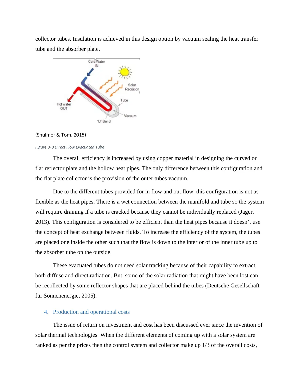
collector tubes. Insulation is achieved in this design option by vacuum sealing the heat transfer
tube and the absorber plate.
(Shulmer & Tom, 2015)
Figure 3- 3 Direct Flow Evacuated Tube
The overall efficiency is increased by using copper material in designing the curved or
flat reflector plate and the hollow heat pipes. The only difference between this configuration and
the flat plate collector is the provision of the outer tubes vacuum.
Due to the different tubes provided for in flow and out flow, this configuration is not as
flexible as the heat pipes. There is a wet connection between the manifold and tube so the system
will require draining if a tube is cracked because they cannot be individually replaced (Jager,
2013). This configuration is considered to be efficient than the heat pipes because it doesn’t use
the concept of heat exchange between fluids. To increase the efficiency of the system, the tubes
are placed one inside the other such that the flow is down to the interior of the inner tube up to
the absorber tube on the outside.
These evacuated tubes do not need solar tracking because of their capability to extract
both diffuse and direct radiation. But, some of the solar radiation that might have been lost can
be recollected by some reflector shapes that are placed behind the tubes (Deutsche Gesellschaft
für Sonnenenergie, 2005).
4. Production and operational costs
The issue of return on investment and cost has been discussed ever since the invention of
solar thermal technologies. When the different elements of coming up with a solar system are
ranked as per the prices then the control system and collector make up 1/3 of the overall costs,
Paraphrase This Document
Need a fresh take? Get an instant paraphrase of this document with our AI Paraphraser
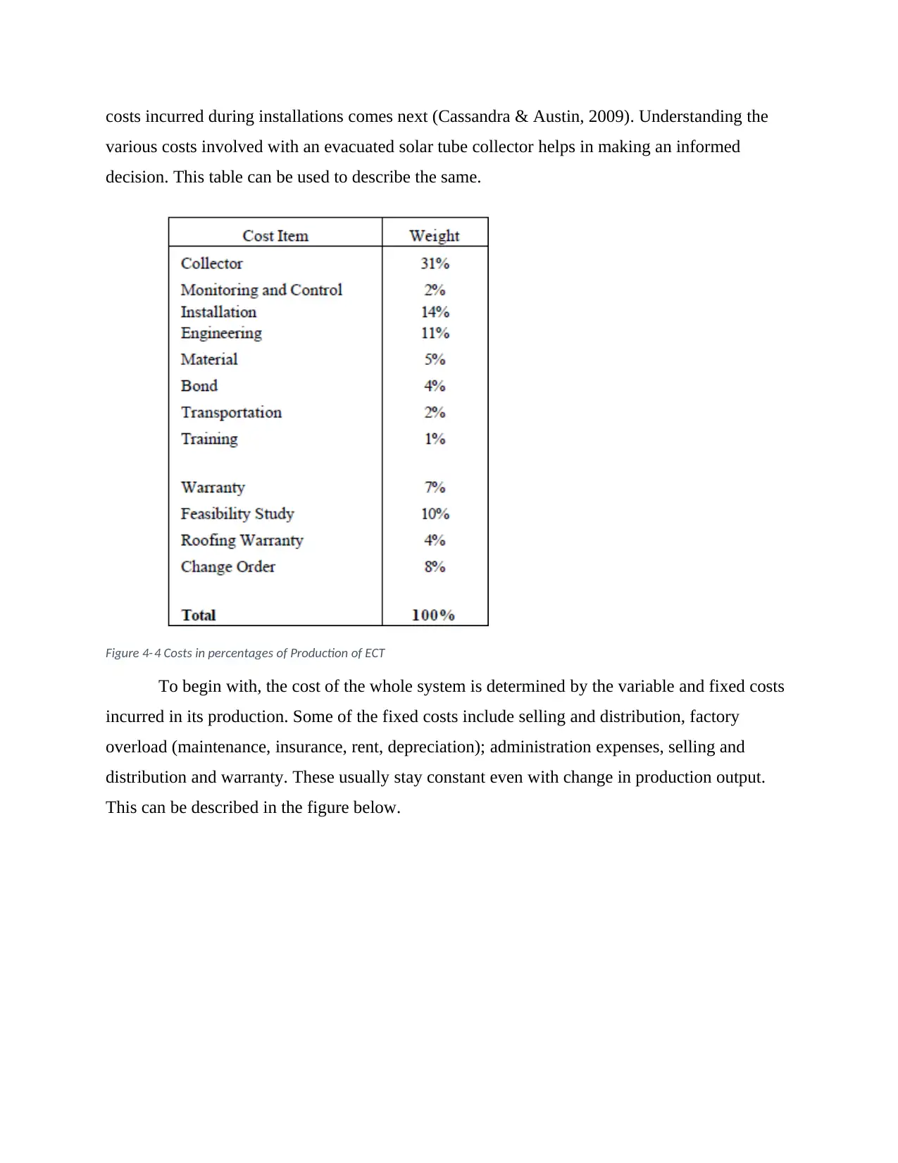
costs incurred during installations comes next (Cassandra & Austin, 2009). Understanding the
various costs involved with an evacuated solar tube collector helps in making an informed
decision. This table can be used to describe the same.
Figure 4- 4 Costs in percentages of Production of ECT
To begin with, the cost of the whole system is determined by the variable and fixed costs
incurred in its production. Some of the fixed costs include selling and distribution, factory
overload (maintenance, insurance, rent, depreciation); administration expenses, selling and
distribution and warranty. These usually stay constant even with change in production output.
This can be described in the figure below.
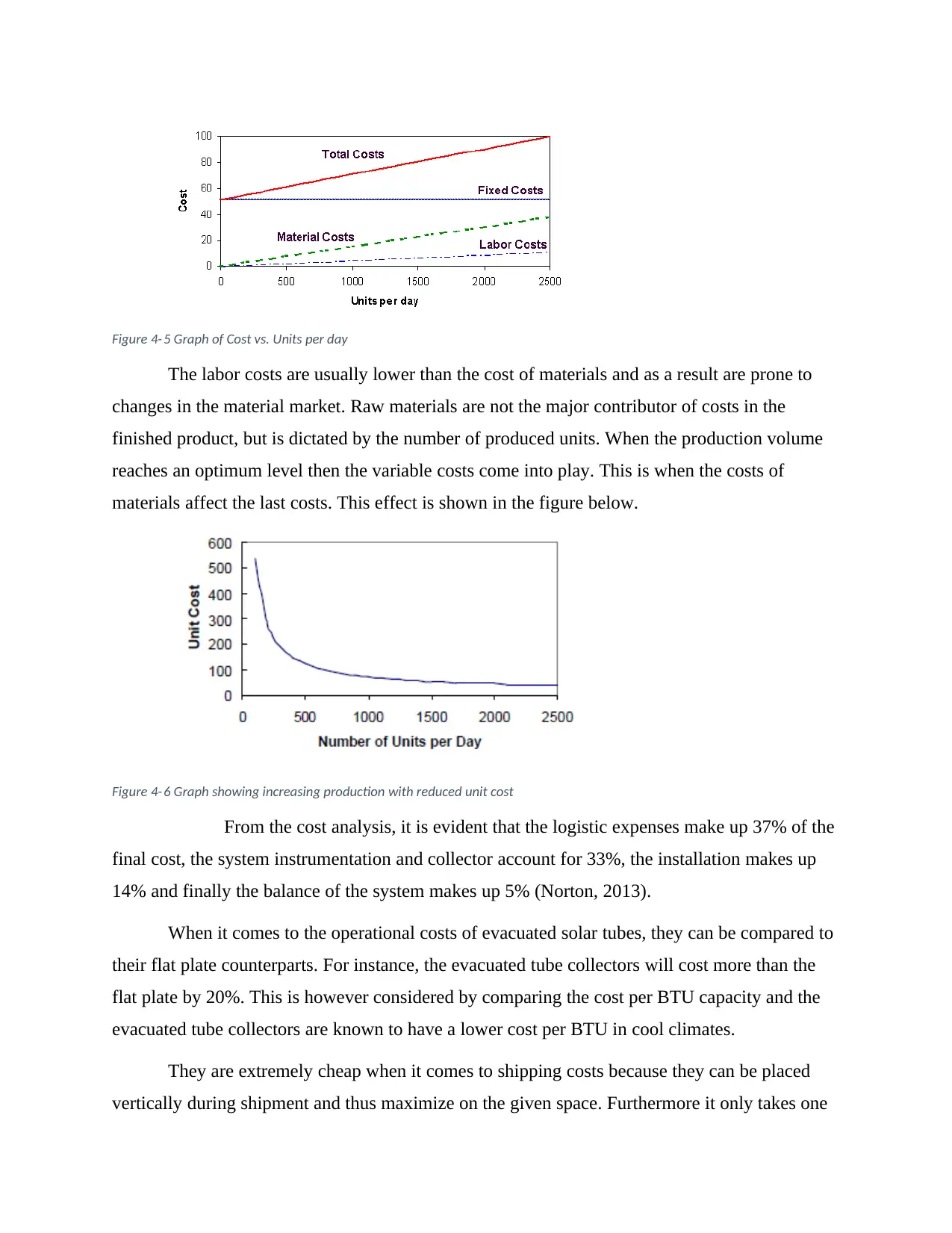
Figure 4- 5 Graph of Cost vs. Units per day
The labor costs are usually lower than the cost of materials and as a result are prone to
changes in the material market. Raw materials are not the major contributor of costs in the
finished product, but is dictated by the number of produced units. When the production volume
reaches an optimum level then the variable costs come into play. This is when the costs of
materials affect the last costs. This effect is shown in the figure below.
Figure 4- 6 Graph showing increasing production with reduced unit cost
From the cost analysis, it is evident that the logistic expenses make up 37% of the
final cost, the system instrumentation and collector account for 33%, the installation makes up
14% and finally the balance of the system makes up 5% (Norton, 2013).
When it comes to the operational costs of evacuated solar tubes, they can be compared to
their flat plate counterparts. For instance, the evacuated tube collectors will cost more than the
flat plate by 20%. This is however considered by comparing the cost per BTU capacity and the
evacuated tube collectors are known to have a lower cost per BTU in cool climates.
They are extremely cheap when it comes to shipping costs because they can be placed
vertically during shipment and thus maximize on the given space. Furthermore it only takes one
person to install it. This makes it easier because the user will not incur additional labor costs for
purposes of installation.
Finally, operating an evacuated tube solar collector depends on the location being used.
For instance, in some regions many collectors are required to heat the same amount of water that
can be heated by only a few collectors.
5. Component technical details
The following assumptions are made while giving the analysis of a solar collector tube
with U-tube.
i. Negligible resistance to thermal effects of the outer glass tube
ii. Conduction of gas is neglected since the vacuum between two glass tubes is perfect
iii. With normal incidence solar radiation angle, we consider steady state conditions
iv. Between the absorber glass tube and the aluminum fin there is a layer of air of small
thickness.
The solar power absorbed S, is equivalent to optical losses times the incident solar power
and can be shown as follows (Santamouris, 2014):
S= ( τα ) G Aa Equation i (Ghoneim, 2017)
Where α- absorptance of the glass cover
τ −Transmittance of the glass cover
G- Collector surface global solar irradiance
Aa −isthe area of the collector arperture
The collector’s heat balance equation for each of its parts can be outlined as follows:
Outer Glass Tube
The vacuum layer in between the space of the inner and outer tube eliminate the
possibility of conduction of heat, this is because the coefficient of heat conduction is below 0.27
x 10-5 W/m C and the level of vacuum is 10-4 Pa.
The equation applied at this point is:
Secure Best Marks with AI Grader
Need help grading? Try our AI Grader for instant feedback on your assignments.
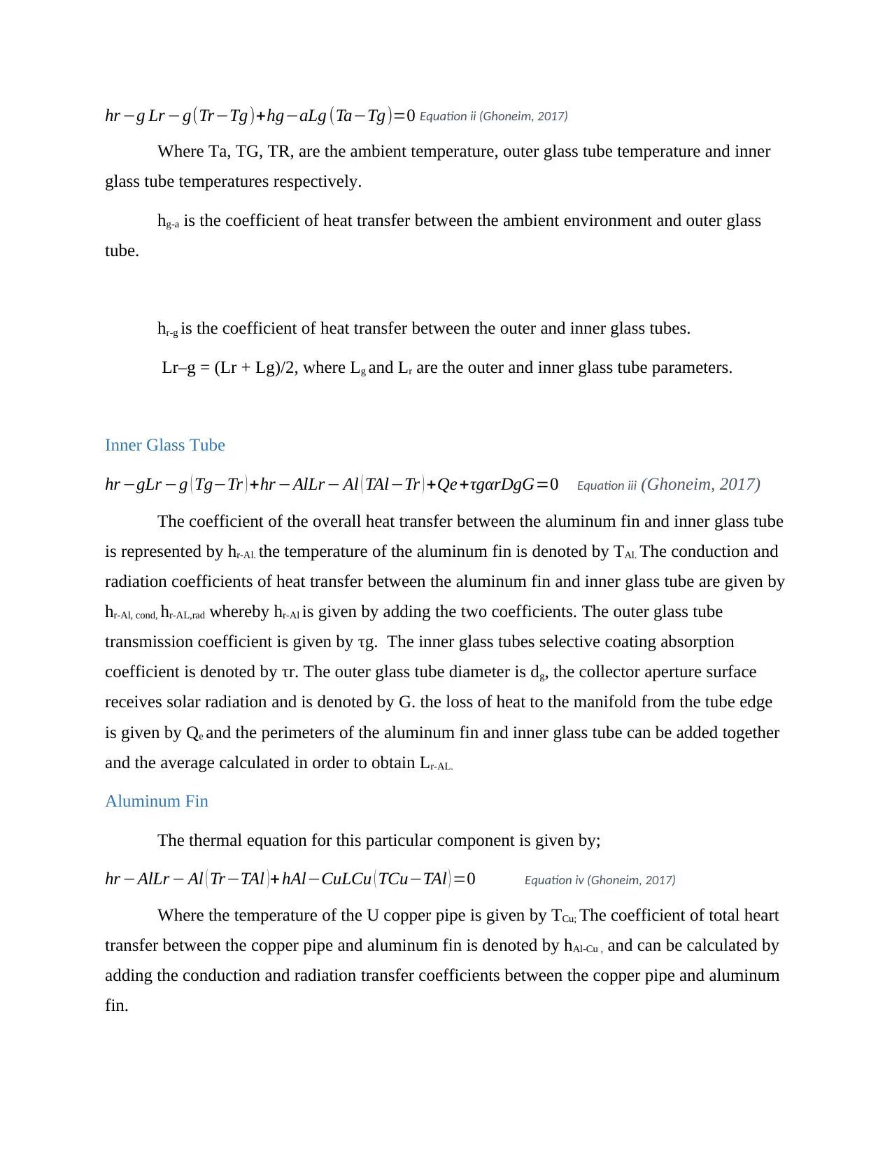
hr −g Lr −g(Tr−Tg)+hg−aLg (Ta−Tg)=0 Equation ii (Ghoneim, 2017)
Where Ta, TG, TR, are the ambient temperature, outer glass tube temperature and inner
glass tube temperatures respectively.
hg-a is the coefficient of heat transfer between the ambient environment and outer glass
tube.
hr-g is the coefficient of heat transfer between the outer and inner glass tubes.
Lr–g = (Lr + Lg)/2, where Lg and Lr are the outer and inner glass tube parameters.
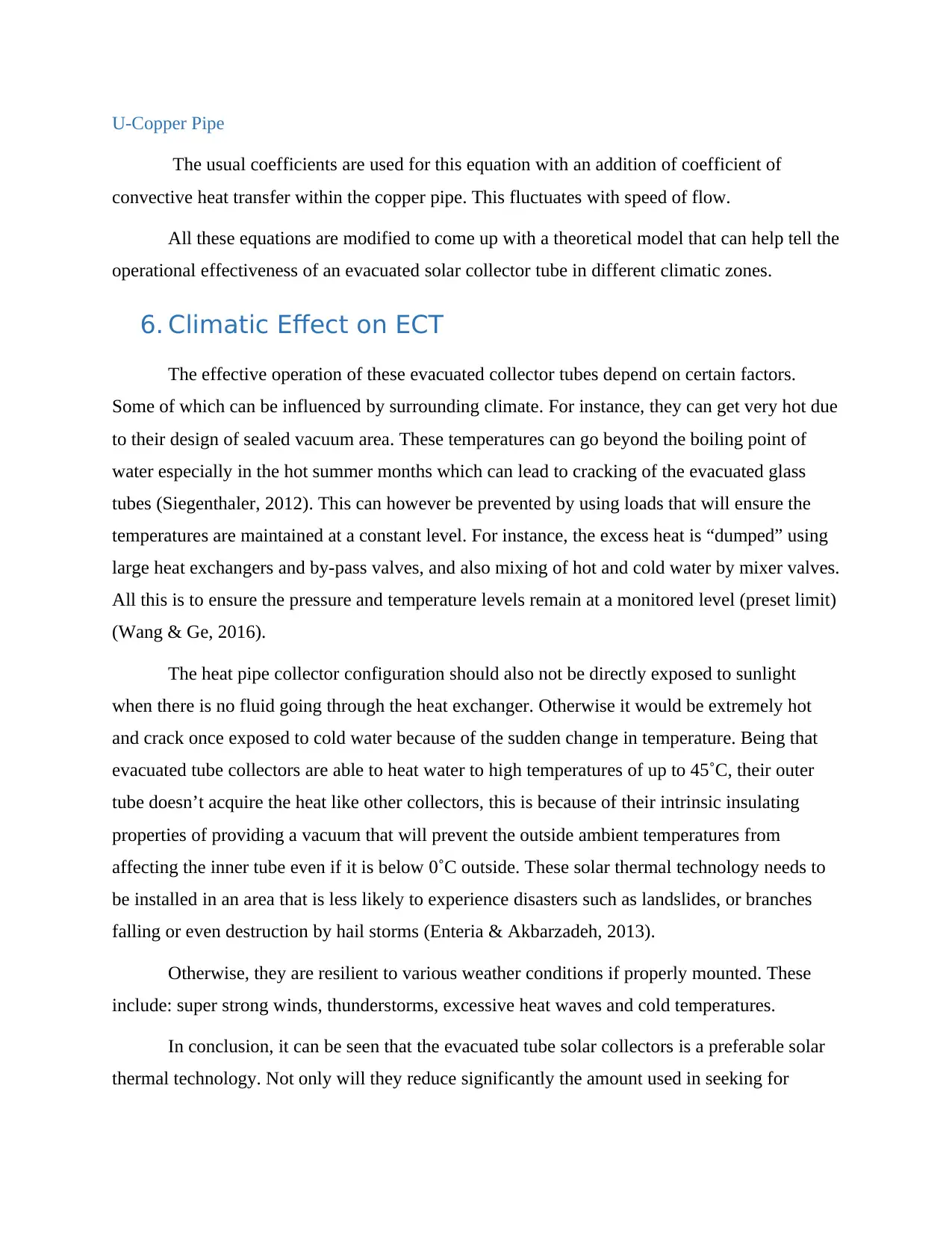
Inner Glass Tube
hr −gLr −g ( Tg−Tr ) +hr −AlLr − Al ( TAl−Tr ) +Qe+τgαrDgG=0 Equation iii (Ghoneim, 2017)
The coefficient of the overall heat transfer between the aluminum fin and inner glass tube
is represented by hr-Al. the temperature of the aluminum fin is denoted by TAl. The conduction and
radiation coefficients of heat transfer between the aluminum fin and inner glass tube are given by
hr-Al, cond, hr-AL,rad whereby hr-Al is given by adding the two coefficients. The outer glass tube
transmission coefficient is given by τg. The inner glass tubes selective coating absorption
coefficient is denoted by τr. The outer glass tube diameter is dg, the collector aperture surface
receives solar radiation and is denoted by G. the loss of heat to the manifold from the tube edge
is given by Qe and the perimeters of the aluminum fin and inner glass tube can be added together
and the average calculated in order to obtain Lr-AL.
Aluminum Fin
The thermal equation for this particular component is given by;
hr −AlLr − Al ( Tr−TAl )+ hAl−CuLCu ( TCu−TAl ) =0 Equation iv (Ghoneim, 2017)
Where the temperature of the U copper pipe is given by TCu; The coefficient of total heart
transfer between the copper pipe and aluminum fin is denoted by hAl-Cu , and can be calculated by
adding the conduction and radiation transfer coefficients between the copper pipe and aluminum
fin.
Where Ta, TG, TR, are the ambient temperature, outer glass tube temperature and inner
glass tube temperatures respectively.
hg-a is the coefficient of heat transfer between the ambient environment and outer glass
tube.
hr-g is the coefficient of heat transfer between the outer and inner glass tubes.
Lr–g = (Lr + Lg)/2, where Lg and Lr are the outer and inner glass tube parameters.
Inner Glass Tube
hr −gLr −g ( Tg−Tr ) +hr −AlLr − Al ( TAl−Tr ) +Qe+τgαrDgG=0 Equation iii (Ghoneim, 2017)
The coefficient of the overall heat transfer between the aluminum fin and inner glass tube
is represented by hr-Al. the temperature of the aluminum fin is denoted by TAl. The conduction and
radiation coefficients of heat transfer between the aluminum fin and inner glass tube are given by
hr-Al, cond, hr-AL,rad whereby hr-Al is given by adding the two coefficients. The outer glass tube
transmission coefficient is given by τg. The inner glass tubes selective coating absorption
coefficient is denoted by τr. The outer glass tube diameter is dg, the collector aperture surface
receives solar radiation and is denoted by G. the loss of heat to the manifold from the tube edge
is given by Qe and the perimeters of the aluminum fin and inner glass tube can be added together
and the average calculated in order to obtain Lr-AL.
Aluminum Fin
The thermal equation for this particular component is given by;
hr −AlLr − Al ( Tr−TAl )+ hAl−CuLCu ( TCu−TAl ) =0 Equation iv (Ghoneim, 2017)
Where the temperature of the U copper pipe is given by TCu; The coefficient of total heart
transfer between the copper pipe and aluminum fin is denoted by hAl-Cu , and can be calculated by
adding the conduction and radiation transfer coefficients between the copper pipe and aluminum
fin.
U-Copper Pipe
The usual coefficients are used for this equation with an addition of coefficient of
convective heat transfer within the copper pipe. This fluctuates with speed of flow.
All these equations are modified to come up with a theoretical model that can help tell the
operational effectiveness of an evacuated solar collector tube in different climatic zones.
6. Climatic Effect on ECT
The effective operation of these evacuated collector tubes depend on certain factors.
Some of which can be influenced by surrounding climate. For instance, they can get very hot due
to their design of sealed vacuum area. These temperatures can go beyond the boiling point of
water especially in the hot summer months which can lead to cracking of the evacuated glass
tubes (Siegenthaler, 2012). This can however be prevented by using loads that will ensure the
temperatures are maintained at a constant level. For instance, the excess heat is “dumped” using
large heat exchangers and by-pass valves, and also mixing of hot and cold water by mixer valves.
All this is to ensure the pressure and temperature levels remain at a monitored level (preset limit)
(Wang & Ge, 2016).
The heat pipe collector configuration should also not be directly exposed to sunlight
when there is no fluid going through the heat exchanger. Otherwise it would be extremely hot
and crack once exposed to cold water because of the sudden change in temperature. Being that
evacuated tube collectors are able to heat water to high temperatures of up to 45˚C, their outer
tube doesn’t acquire the heat like other collectors, this is because of their intrinsic insulating
properties of providing a vacuum that will prevent the outside ambient temperatures from
affecting the inner tube even if it is below 0˚C outside. These solar thermal technology needs to
be installed in an area that is less likely to experience disasters such as landslides, or branches
falling or even destruction by hail storms (Enteria & Akbarzadeh, 2013).
Otherwise, they are resilient to various weather conditions if properly mounted. These
include: super strong winds, thunderstorms, excessive heat waves and cold temperatures.
In conclusion, it can be seen that the evacuated tube solar collectors is a preferable solar
thermal technology. Not only will they reduce significantly the amount used in seeking for

alternative means of solar thermal technology on a monthly basis. But also encourages healthy
living because they solely rely on the suns energy to produce heat. All this coupled with modern
technology, has given this option an upper hand because it can now be sourced easily in terms of
design thus making it a profitable venture also for market providers.
living because they solely rely on the suns energy to produce heat. All this coupled with modern
technology, has given this option an upper hand because it can now be sourced easily in terms of
design thus making it a profitable venture also for market providers.
Paraphrase This Document
Need a fresh take? Get an instant paraphrase of this document with our AI Paraphraser
References
Breeze, P., Sorensen, B., Storvick, T., & Barbir, F. (2008). Renewable Energy Focus Handbook.
Massachusetts: Academic Press.
Cassandra, G., & Austin, J. (2009). Costs in Solar Thermal Thermal Technologies . New York: John Wiley &
Sons.
Colombo, E., Bologna, S., & Masera, D. (2013). Renewable Energy for Unleashing Sustainable
Development. Berlin: Springer Science & Business Media.
Deutsche Gesellschaft für Sonnenenergie. (2005). Planning and Installing Solar Thermal Systems: A
Guide for Installers, Architects, and Engineers. UK: Earthscan.
Duffie, J. A., & Beckman, W. (2013). Solar Engineering of Thermal Processes. New Jersey: John,Wiley &
Sons .
Enteria, N., & Akbarzadeh, A. (2013). Solar Energy Sciences and Engineering Applications. Florida: CRC
Press.
Ghoneim, A. (2017). Optimization of Evacuated Tube Collector Parameters for Solar Industrial Process
Heat. International Journal of Energy and Environmental Research, 61-63.
Hough, T. P. (2006). Solar Energy: New Research. New York: Nova Publishers.
Jager, F. (2013). Solar Energy Applications in Houses: Performance and Economics in Europe. New York:
Elsevier Science.
Kalogirou, S. A. (2009). Solar Energy Engineering: Processes and Systems. Cambridge: Academic Press.
Kitcher, C. (2012). A Practical Guide to Renewable Energy: Power Systems and their Installation.
Abingdon: Routledge.
Laughton, C. (2010). Solar Domestic Water Heating: The Earthscan Expert Handbook for Planning,
Design and Installation. UK: Earthscan.
Mike, S., & D, N. (2016). Solar Heating Technology . Berlin: Springer .
Mukhtar, A. (2017). Operation and Control of Renewable Energy Systems. New Jersey : John Wiley &
Sons.
Norton, B. (2013). Harnessing Solar Heat. Berlin : Springer Science & Business Media.
Nusz, B., & Ramlow, B. (2010). Solar Water Heating--Revised & Expanded Edition: A Comprehensive
Guide to Solar Water and Space Heating Systems. Canada: New Society Publishers.
Santamouris, M. (2014). Solar Thermal Technologies for Buildings: The State of the Art. Abingdon:
Routledge.
Shulmer, W., & Tom, F. (2015). Evacuated Solar Tube Collectors . Chicago: John, Wiley & Sons.
Siegenthaler, J. (2012). Modern Hydronic Heating: For Residential and Light Commercial Buildings.
Boston: Cengage Learning.
Sobhansarbandi, S. (2017). Evacuated Tube Solar Collector Integrated with Multifunctional Absorption-
storage Materials. Texas: University of Texas at Dallas.
Vijayakumar, P., Vijayakumar, S., & Kumar, S. (2017). Comparison of evacuated tube and flat plate solar
collector – A review. Chicago: John, Wiley & Sons.
Wang, R., & Ge, T. (2016). Advances in Solar Heating and Cooling. New York: Elsevier Science.
Zhao, Y., & Goswami, Y. (2009). Proceedings of ISES World Congress 2007 (Vol.1-Vol.5): Solar Energy and
Human Settlement. Berlin: Springer Science & Business Media.
1 out of 15
Related Documents


Your All-in-One AI-Powered Toolkit for Academic Success.
+13062052269
info@desklib.com
Available 24*7 on WhatsApp / Email
![[object Object]](/_next/static/media/star-bottom.7253800d.svg)
Unlock your academic potential
© 2024 | Zucol Services PVT LTD | All rights reserved.