Analysis of Wind Energy Conversion Systems and Power Electronics
VerifiedAdded on 2020/05/16
|11
|2295
|134
AI Summary
The document provides a comprehensive analysis of wind energy systems, emphasizing the importance of power electronics such as doubly-fed induction generators (DFIGs) for connecting to the grid. It discusses how the rotor's magnetic fields interact with generator speed, affecting frequency output in both synchronized and asynchronous conditions. The text also covers static compensators' role in stabilizing power systems and highlights advancements in motor-generator technologies for optimizing wind energy conversion. By referencing multiple sources on electrical drives and renewable energy applications, it illustrates current challenges and solutions within the field of wind energy engineering.

Running head: INDUCTION GENERATORS IN WIND TURBINES
INDUCTION GENERATORS IN WIND TURBINES
[Author Name(s), First M. Last, Omit Titles and Degrees]
[Institutional Affiliation(s)]
INDUCTION GENERATORS IN WIND TURBINES
[Author Name(s), First M. Last, Omit Titles and Degrees]
[Institutional Affiliation(s)]
Paraphrase This Document
Need a fresh take? Get an instant paraphrase of this document with our AI Paraphraser
2
INDUCTION GENERATORS IN WIND TURBINES
The classical Danish Concept describes a wind turbine consisting of a stall-controlled
rotor with three rotor blades, a gearbox, a pole-switched asynchronous generator with squirrel
cage rotor and a direct mains grid coupling (Letcher, 2017). A constant-speed system is produced
by the direct grid coupling and with the presence of an almost constant speed of operation in the
super-asynchronous slip area. It is possible to adjust the speed of the rotor using a slip control
within the narrow limits. The speed of the rotor can as well be adjusted in wider ranges through
switching the poles of the generator. The revolutions of the rotor are adapted to the speed of the
generator by the gearbox.
Back then, the power that was used in the building up of the rotating filed was being
extracted from the grid (Kouro, 2011). This led to the use of softs-starters between the grid and
the generator in order to limit the inrush currents that were produced when the generator is
coupled with the grid. Unfortunately, this process of limitation was not ideal hence; it was found
that some inrush currents still made their way into the system. Technical challenges among them
the process of equalization that occurs at the grid connection resulting from switching actions
used in the adjustment of power, the approach of direct-grid is no longer adopted in large wind
turbines (Letcher, 2017).
Instead of the direct coupling approach, the large wind turbines are using the modified
Danish concept. In this concept, a double-fed asynchronous machine acts as a generator. In this
design, the voltage and the frequency of the stator have been coupled very tightly with the mains
grid, while a special inverter has been used in coupling the rotor of the slip ring with grid. This
coupling must be able ensure energy is transmitted towards the machine as well as towards the
grid. The specification of the inverter is based on the power of the slip, which is in most cases
about 20% of the generator’s rated power (Chakraborty, 2013).
3
INDUCTION GENERATORS IN WIND TURBINES
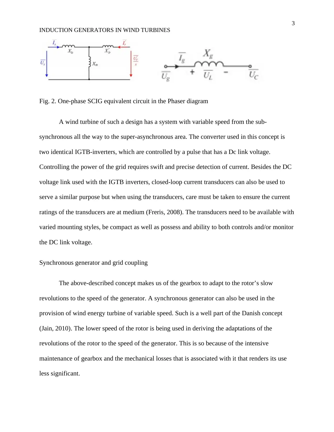
Fig. 2. One-phase SCIG equivalent circuit in the Phaser diagram
A wind turbine of such a design has a system with variable speed from the sub-
synchronous all the way to the super-asynchronous area. The converter used in this concept is
two identical IGTB-inverters, which are controlled by a pulse that has a Dc link voltage.
Controlling the power of the grid requires swift and precise detection of current. Besides the DC
voltage link used with the IGTB inverters, closed-loop current transducers can also be used to
serve a similar purpose but when using the transducers, care must be taken to ensure the current
ratings of the transducers are at medium (Freris, 2008). The transducers need to be available with
varied mounting styles, be compact as well as possess and ability to both controls and/or monitor
the DC link voltage.
Synchronous generator and grid coupling
The above-described concept makes us of the gearbox to adapt to the rotor’s slow
revolutions to the speed of the generator. A synchronous generator can also be used in the
provision of wind energy turbine of variable speed. Such is a well part of the Danish concept
(Jain, 2010). The lower speed of the rotor is being used in deriving the adaptations of the
revolutions of the rotor to the speed of the generator. This is so because of the intensive
maintenance of gearbox and the mechanical losses that is associated with it that renders its use
less significant.
⊘ This is a preview!⊘
Do you want full access?
Subscribe today to unlock all pages.

Trusted by 1+ million students worldwide

4
INDUCTION GENERATORS IN WIND TURBINES
The mechanical power delivered by the blades of the windmill determines the size of the
synchronous generator that would be used. The adoption of torque that has permanent rotors of
magnet would be the most suitable for this system since the system will be of slow speed and
high torque. Such torque motors are able to support to high levels of powers. Synchronous
multipole generators that have wound rotor are usable for larger systems that would be releasing
higher power values (Kumar, 2014).
The ability to provide either capacitive or inductive power based on the excitation
control/ control of the field is the main advantage of the synchronous generators. A pulse
converter is used in the mains grid coupling as the converter is normally to the specifications of
the intended power transmission. In the case of harsh environments, moulded versions of LEM’s
dynamic closed-loop current transducers are used as the rectifiers and the converters. Under
ordinary conditions, the closed-loop current transducers are not moulded but instead just used as
they are as the inverter and in the rectifier (Tabatabaei, 2013).
The above applications can use all the available LF-Family current transducers due to
their good common behavior and high accuracy levels that stand at 0.3% at ambient room
temperature. It is possible to make sort-circuit protection by the use of the closed-loop principle
(U.A.Bakshi, 2010). The short-circuit protection is made of the power semiconductors that are
found in the inverters. This forms a very powerful advantage of turbines of wind energy
especially in the offshore areas where maintenance of the turbines poses a challenge as well as
being expensive. The currently used transducers are major components of the wind energy
turbines of the modern day. These transducers provide the wind energy turbines with a lot
advantages that make their use ever on the increase.
Paraphrase This Document
Need a fresh take? Get an instant paraphrase of this document with our AI Paraphraser

5
INDUCTION GENERATORS IN WIND TURBINES
Generating mode of operation at sub-synchronous and super-synchronous speed
Synchnronous speed referes to the speed of rotattion of a magnetic field in a motor. This
speed is a fcator of the design of the motor such that in some designs the mechanical speed of the
magntitc fields may be euivalent to the spped of rotattion o th magnrtic files. Such a case is
termed as synchronous motor whereas in other caes the mechnical speed may beraltively lower
hence refreed to as asynchronous motor (Machowski, 2011). Syncrhonous speed depends on the
number of poles present in a motor and the electrucal frequcncuy of themagentic fields of the
motor. Synchronnous speed is estimated form the equation
Suync. Speed(in RPM)=120*Frequecny* No. of poles
Fig. 3. Phaser diagram of the stator voltage, the stator current, the rotor voltage and the rotor
current. (a) Super synchronous mode (b) Sub synchronous mode

6
INDUCTION GENERATORS IN WIND TURBINES
Fig. 4. Phaser diagram of GSC output voltage and current. (a) Super synchronous mode (b) Sub
synchronous mode
Synchronous motor are found to habe either permanent magnet p DC winding in their rotor and
normally rotate at the synchrnounous speed (Shahnia, 2014). Asynchrnonous motors on the
other hand deploy indcytion to generate the field of their rotor in most cases rotates at speeds that
are slighlty lower than the synchronous speeds.
An induction machine generally has three modes of operation including the generator, motor and
brake modes. There are three main components of the power that flow into the rotor of the slip
ring of the induction machine (Sen, 2013). These components include the mechanical power,
electromagnetic power and the slip power. The electromagnetic power is the power that is
transferred between the rotor and the stator via the air gap while the mechanical power is
transferred between the shaft and the rotor (Smith, 2012). Slip power is transferred between any
available external electrical load or source and the rotor and it is transferred through the slip
rings of the rotor
Pr (slip power) = Pc+ Pcur where Pc and Pcur are the converter output and rotor copper losses
respectively (Leonhard, 2012). Under any conditions, the three components of rotor power have
a correlation such that
⊘ This is a preview!⊘
Do you want full access?
Subscribe today to unlock all pages.

Trusted by 1+ million students worldwide
7
INDUCTION GENERATORS IN WIND TURBINES
Pg= Pm+Pr= (1-s) Pg+sPg
Pm= (1-s) Pg
Pr= sPg where s which is the slip is equivalent to (ns-n)/ns
The terminal voltage Vc of the converter is a factor of the phase, frequency and magnitude and in
most cases its frequency is controlled such that it is always equal to frequency of the voltage of
the induced rotor, Er
Er= Erej0= Er (Muyeen, 2012)
The voltage terminal can thus be expressed as
V c=V c
ejγ=V c ( cos γ + jsin γ ) CITATION Far14 \l 1033 (Shahnia, 2014)
Using the motor resistance as Rr and the reactance of the leakage of the rotor when standstill as
Xr, the rotor current in any of the slips can then be determined using the equation:
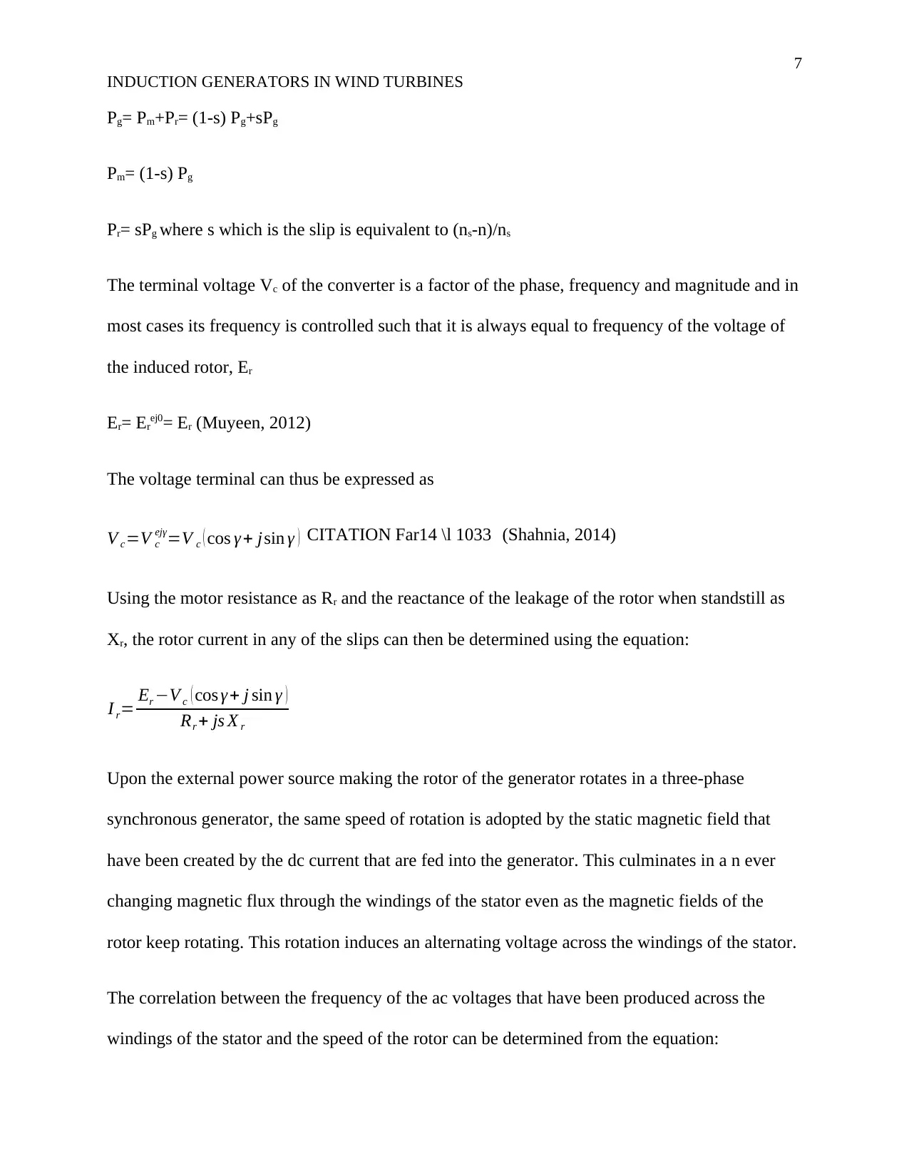
I r= Er −V c ( cos γ + j sin γ )
Rr + js X r
Upon the external power source making the rotor of the generator rotates in a three-phase
synchronous generator, the same speed of rotation is adopted by the static magnetic field that
have been created by the dc current that are fed into the generator. This culminates in a n ever
changing magnetic flux through the windings of the stator even as the magnetic fields of the
rotor keep rotating. This rotation induces an alternating voltage across the windings of the stator.
The correlation between the frequency of the ac voltages that have been produced across the
windings of the stator and the speed of the rotor can be determined from the equation:
Paraphrase This Document
Need a fresh take? Get an instant paraphrase of this document with our AI Paraphraser
8
INDUCTION GENERATORS IN WIND TURBINES
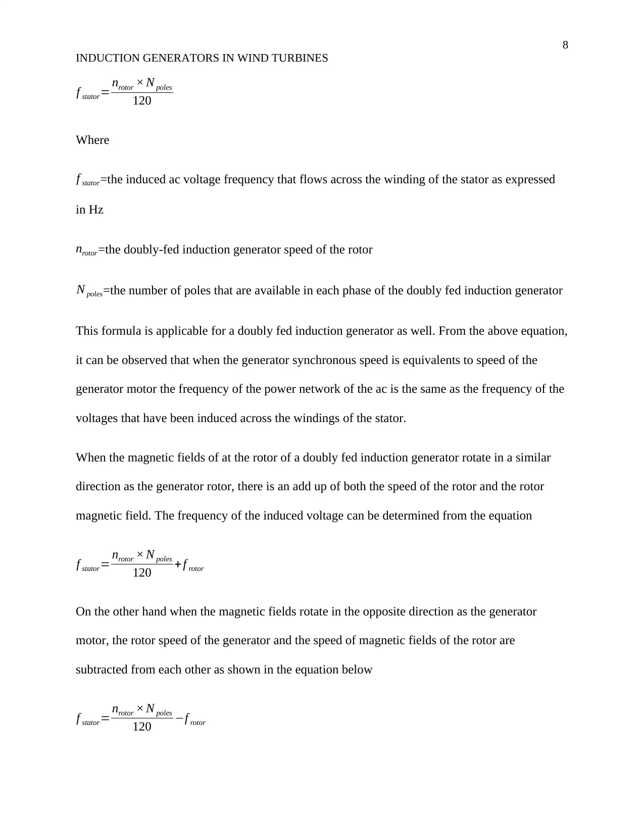
f stator= nrotor × N poles
120
Where
f stator=the induced ac voltage frequency that flows across the winding of the stator as expressed
in Hz
nrotor =the doubly-fed induction generator speed of the rotor
N poles=the number of poles that are available in each phase of the doubly fed induction generator
This formula is applicable for a doubly fed induction generator as well. From the above equation,
it can be observed that when the generator synchronous speed is equivalents to speed of the
generator motor the frequency of the power network of the ac is the same as the frequency of the
voltages that have been induced across the windings of the stator.
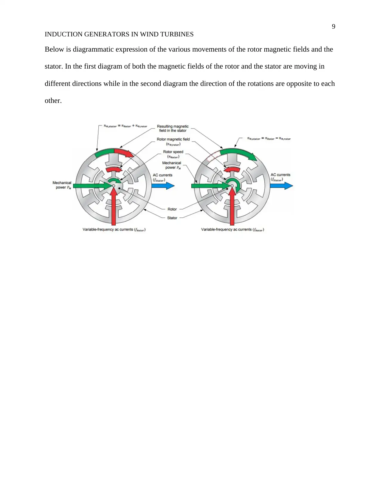
When the magnetic fields of at the rotor of a doubly fed induction generator rotate in a similar
direction as the generator rotor, there is an add up of both the speed of the rotor and the rotor
magnetic field. The frequency of the induced voltage can be determined from the equation
f stator= nrotor × N poles
120 + f rotor
On the other hand when the magnetic fields rotate in the opposite direction as the generator
motor, the rotor speed of the generator and the speed of magnetic fields of the rotor are
subtracted from each other as shown in the equation below
f stator= nrotor × N poles
120 −f rotor
9
INDUCTION GENERATORS IN WIND TURBINES
Below is diagrammatic expression of the various movements of the rotor magnetic fields and the
stator. In the first diagram of both the magnetic fields of the rotor and the stator are moving in
different directions while in the second diagram the direction of the rotations are opposite to each
other.
⊘ This is a preview!⊘
Do you want full access?
Subscribe today to unlock all pages.

Trusted by 1+ million students worldwide
10
INDUCTION GENERATORS IN WIND TURBINES
References
Ackermann, T. (2012). Wind Power in Power Systems. London: John Wiley & Sons.
Chakraborty, S. (2013). Power Electronics for Renewable and Distributed Energy Systems: A
Sourcebook of Topologies, Control and Integration. New Delhi: Springer Science &
Business Media.
Freris, L. (2008). Renewable Energy in Power Systems. London: John Wiley & Sons.
Hindmarsh, J. (2014). Electrical Machines & their Applications. Chicago: Elsevier.
Jain, P. (2010). Wind Energy Engineering. London: McGraw Hill Professional.
Kouro, S. (2011). Power Conversion and Control of Wind Energy Systems. Beijing: John Wiley
& Sons.
Kumar, A. (2014). Dfig-Based Wind Power Conversion Systemconnected to Grid. Sydney:
GRIN Verlag.
Leonhard, W. (2012). Control of Electrical Drives. Oxford: Springer Science & Business Media.
Letcher, T. M. (2017). Wind Energy Engineering: A Handbook for Onshore and Offshore Wind
Turbines. Manchester: Elsevier Science.
Machowski, J. (2011). Power System Dynamics: Stability and Control. Beijing: John Wiley &
Sons.
Muyeen, S. (2012). Wind Energy Conversion Systems: Technology and Trend. New York:
Springer Science & Business Media.
Paraphrase This Document
Need a fresh take? Get an instant paraphrase of this document with our AI Paraphraser
11
INDUCTION GENERATORS IN WIND TURBINES
Sen, P. C. (2013). Principles of Electric Machines and Power Electronics, 3rd Edition: Third
Edition. New York: Wiley Global Education.
Shahnia, F. (2014). Static Compensators (STATCOMs) in Power Systems. New York: Springer.
Smith, N. (2012). Motors as Generators for Micro Hydro Power. London: Practical Action
Publishing.
Tabatabaei, N. M. (2013). Reactive Power Control in AC Power Systems: Fundamentals and
Current Issues. Kansas: Springer.
U.A.Bakshi, M. (2010). Electrical Machines I. New York: Technical Publications.
1 out of 11
Related Documents
Your All-in-One AI-Powered Toolkit for Academic Success.
+13062052269
info@desklib.com
Available 24*7 on WhatsApp / Email
![[object Object]](/_next/static/media/star-bottom.7253800d.svg)
Unlock your academic potential
Copyright © 2020–2026 A2Z Services. All Rights Reserved. Developed and managed by ZUCOL.


