Interim Report: Design and Analysis of Stub Feed Dipole Slot Antenna
VerifiedAdded on 2019/09/23
|6
|2416
|325
Report
AI Summary
This report provides an in-depth analysis of a stub feed dipole slot antenna, a design chosen for its ease of construction and transmission capabilities. It explores the influence of dimensions and port placement on antenna performance, utilizing CST software for simulation and optimization. The report details the concept of feed impedance, its role in power transmission, and the application of Babinet's principle in antenna design. It covers the transition from a dipole antenna to a slot antenna, including polarization and radiation characteristics. The report also discusses stub matching techniques for impedance optimization, simulation results with varying dimensions, and the use of a network analyzer. The appendix includes information on patch antennas, S-parameters, and vector network analyzers, providing a comprehensive overview of antenna design and analysis.
1
Abstract The antenna in which we will be talking about in this report will be the stub feed dipole slot antenna. It is used a lot in
this industry. This is because of its easiness to make and its brilliant transmission distances. When you’re creating something like
this, the length, width and placement of the port can affect the antenna. So those dimensions need to be correct. The software that
is used to perfect this is CST. The CST software is used to prototype the work. The CST software assesses the information we
have created using that the S-parameter results are also analyzed. So every time the parameters are changed the information that
was made also changes. However they both need to be in agreement with each other that is when the design is made. The CST
software have an analyzer called the S11 analyzer, this tool helps the source transmit information to the antenna. If analysis is
good enough the design is made.
Keywords — Stub fed, antenna, CST, feed impedance.
.
I. INTRODUCTION1
hen a wire goes through a magnetic field an electric
current is transferred to the wire inductively.an
electromagnetic wave is now created which now moves
back and forth. An antenna is a part of cable. The cable is
moving through the magnetic field. This transfers a very
tiny current in the antenna. This is then amplified to a level
that can then be used, for example can be used as a
transistor. The transmitter converts an electrical signal into
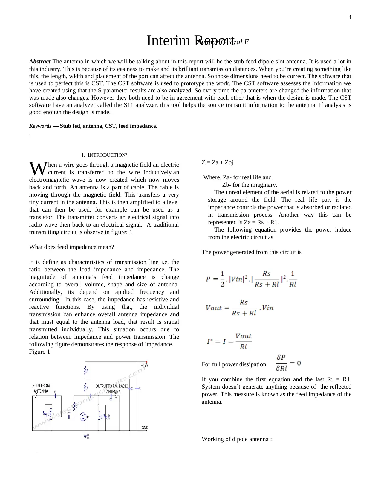
radio wave then back to an electrical signal. A traditional
transmitting circuit is observe in figure: 1
W
What does feed impedance mean?
It is define as characteristics of transmission line i.e. the
ratio between the load impedance and impedance. The
magnitude of antenna’s feed impedance is change
according to overall volume, shape and size of antenna.
Additionally, its depend on applied frequency and
surrounding. In this case, the impedance has resistive and
reactive functions. By using that, the individual
transmission can enhance overall antenna impedance and
that must equal to the antenna load, that result is signal
transmitted individually. This situation occurs due to
relation between impedance and power transmission. The
following figure demonstrates the response of impedance.
Figure 1
1
Z = Za + Zbj
Where, Za- for real life and
Zb- for the imaginary.
The unreal element of the aerial is related to the power
storage around the field. The real life part is the
impedance controls the power that is absorbed or radiated
in transmission process. Another way this can be
represented is Za = Rs + R1.
The following equation provides the power induce
from the electric circuit as
The power generated from this circuit is
For full power dissipation
If you combine the first equation and the last Rr = R1.
System doesn’t generate anything because of the reflected
power. This measure is known as the feed impedance of the
antenna.
Working of dipole antenna :
Interim ReportAmmar Ghazal E
Abstract The antenna in which we will be talking about in this report will be the stub feed dipole slot antenna. It is used a lot in
this industry. This is because of its easiness to make and its brilliant transmission distances. When you’re creating something like
this, the length, width and placement of the port can affect the antenna. So those dimensions need to be correct. The software that
is used to perfect this is CST. The CST software is used to prototype the work. The CST software assesses the information we
have created using that the S-parameter results are also analyzed. So every time the parameters are changed the information that
was made also changes. However they both need to be in agreement with each other that is when the design is made. The CST
software have an analyzer called the S11 analyzer, this tool helps the source transmit information to the antenna. If analysis is
good enough the design is made.
Keywords — Stub fed, antenna, CST, feed impedance.
.
I. INTRODUCTION1
hen a wire goes through a magnetic field an electric
current is transferred to the wire inductively.an
electromagnetic wave is now created which now moves
back and forth. An antenna is a part of cable. The cable is
moving through the magnetic field. This transfers a very
tiny current in the antenna. This is then amplified to a level
that can then be used, for example can be used as a
transistor. The transmitter converts an electrical signal into
radio wave then back to an electrical signal. A traditional
transmitting circuit is observe in figure: 1
W
What does feed impedance mean?
It is define as characteristics of transmission line i.e. the
ratio between the load impedance and impedance. The
magnitude of antenna’s feed impedance is change
according to overall volume, shape and size of antenna.
Additionally, its depend on applied frequency and
surrounding. In this case, the impedance has resistive and
reactive functions. By using that, the individual
transmission can enhance overall antenna impedance and
that must equal to the antenna load, that result is signal
transmitted individually. This situation occurs due to
relation between impedance and power transmission. The
following figure demonstrates the response of impedance.
Figure 1
1
Z = Za + Zbj
Where, Za- for real life and
Zb- for the imaginary.
The unreal element of the aerial is related to the power
storage around the field. The real life part is the
impedance controls the power that is absorbed or radiated
in transmission process. Another way this can be
represented is Za = Rs + R1.
The following equation provides the power induce
from the electric circuit as
The power generated from this circuit is
For full power dissipation
If you combine the first equation and the last Rr = R1.
System doesn’t generate anything because of the reflected
power. This measure is known as the feed impedance of the
antenna.
Working of dipole antenna :
Interim ReportAmmar Ghazal E
Paraphrase This Document
Need a fresh take? Get an instant paraphrase of this document with our AI Paraphraser
2
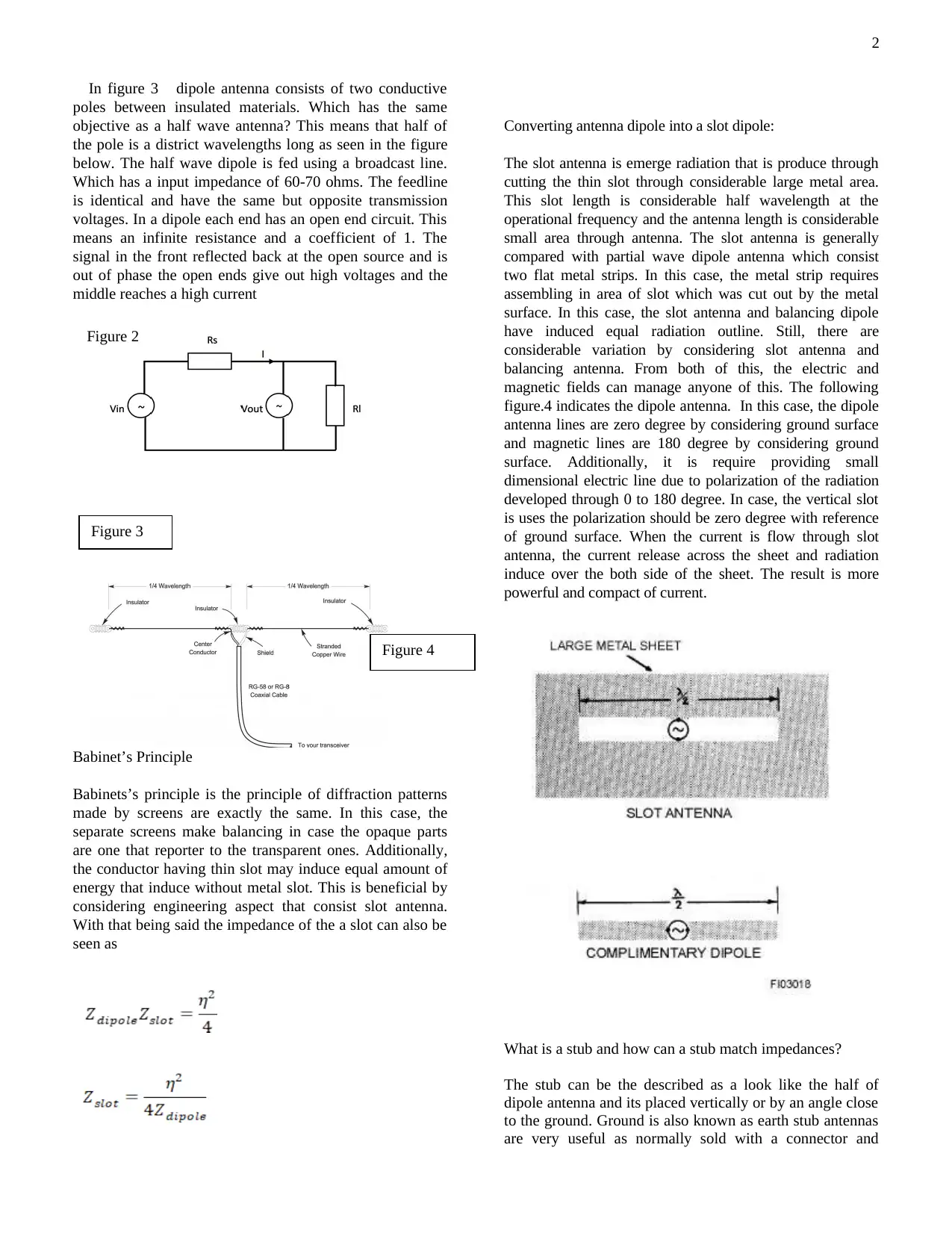
In figure 3 dipole antenna consists of two conductive
poles between insulated materials. Which has the same
objective as a half wave antenna? This means that half of
the pole is a district wavelengths long as seen in the figure
below. The half wave dipole is fed using a broadcast line.
Which has a input impedance of 60-70 ohms. The feedline
is identical and have the same but opposite transmission
voltages. In a dipole each end has an open end circuit. This
means an infinite resistance and a coefficient of 1. The
signal in the front reflected back at the open source and is
out of phase the open ends give out high voltages and the
middle reaches a high current
Babinet’s Principle
Babinets’s principle is the principle of diffraction patterns
made by screens are exactly the same. In this case, the
separate screens make balancing in case the opaque parts
are one that reporter to the transparent ones. Additionally,
the conductor having thin slot may induce equal amount of
energy that induce without metal slot. This is beneficial by
considering engineering aspect that consist slot antenna.
With that being said the impedance of the a slot can also be
seen as
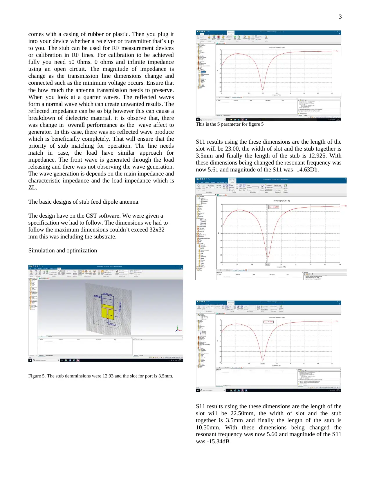
Converting antenna dipole into a slot dipole:
The slot antenna is emerge radiation that is produce through
cutting the thin slot through considerable large metal area.
This slot length is considerable half wavelength at the
operational frequency and the antenna length is considerable
small area through antenna. The slot antenna is generally
compared with partial wave dipole antenna which consist
two flat metal strips. In this case, the metal strip requires
assembling in area of slot which was cut out by the metal
surface. In this case, the slot antenna and balancing dipole
have induced equal radiation outline. Still, there are
considerable variation by considering slot antenna and
balancing antenna. From both of this, the electric and
magnetic fields can manage anyone of this. The following
figure.4 indicates the dipole antenna. In this case, the dipole
antenna lines are zero degree by considering ground surface
and magnetic lines are 180 degree by considering ground
surface. Additionally, it is require providing small
dimensional electric line due to polarization of the radiation
developed through 0 to 180 degree. In case, the vertical slot
is uses the polarization should be zero degree with reference
of ground surface. When the current is flow through slot
antenna, the current release across the sheet and radiation
induce over the both side of the sheet. The result is more
powerful and compact of current.
What is a stub and how can a stub match impedances?
The stub can be the described as a look like the half of
dipole antenna and its placed vertically or by an angle close
to the ground. Ground is also known as earth stub antennas
are very useful as normally sold with a connector and
Figure 2
Figure 3
Figure 4
In figure 3 dipole antenna consists of two conductive
poles between insulated materials. Which has the same
objective as a half wave antenna? This means that half of
the pole is a district wavelengths long as seen in the figure
below. The half wave dipole is fed using a broadcast line.
Which has a input impedance of 60-70 ohms. The feedline
is identical and have the same but opposite transmission
voltages. In a dipole each end has an open end circuit. This
means an infinite resistance and a coefficient of 1. The
signal in the front reflected back at the open source and is
out of phase the open ends give out high voltages and the
middle reaches a high current
Babinet’s Principle
Babinets’s principle is the principle of diffraction patterns
made by screens are exactly the same. In this case, the
separate screens make balancing in case the opaque parts
are one that reporter to the transparent ones. Additionally,
the conductor having thin slot may induce equal amount of
energy that induce without metal slot. This is beneficial by
considering engineering aspect that consist slot antenna.
With that being said the impedance of the a slot can also be
seen as
Converting antenna dipole into a slot dipole:
The slot antenna is emerge radiation that is produce through
cutting the thin slot through considerable large metal area.
This slot length is considerable half wavelength at the
operational frequency and the antenna length is considerable
small area through antenna. The slot antenna is generally
compared with partial wave dipole antenna which consist
two flat metal strips. In this case, the metal strip requires
assembling in area of slot which was cut out by the metal
surface. In this case, the slot antenna and balancing dipole
have induced equal radiation outline. Still, there are
considerable variation by considering slot antenna and
balancing antenna. From both of this, the electric and
magnetic fields can manage anyone of this. The following
figure.4 indicates the dipole antenna. In this case, the dipole
antenna lines are zero degree by considering ground surface
and magnetic lines are 180 degree by considering ground
surface. Additionally, it is require providing small
dimensional electric line due to polarization of the radiation
developed through 0 to 180 degree. In case, the vertical slot
is uses the polarization should be zero degree with reference
of ground surface. When the current is flow through slot
antenna, the current release across the sheet and radiation
induce over the both side of the sheet. The result is more
powerful and compact of current.
What is a stub and how can a stub match impedances?
The stub can be the described as a look like the half of
dipole antenna and its placed vertically or by an angle close
to the ground. Ground is also known as earth stub antennas
are very useful as normally sold with a connector and
Figure 2
Figure 3
Figure 4
3
comes with a casing of rubber or plastic. Then you plug it
into your device whether a receiver or transmitter that’s up
to you. The stub can be used for RF measurement devices
or calibration in RF lines. For calibration to be achieved
fully you need 50 0hms. 0 ohms and infinite impedance
using an open circuit. The magnitude of impedance is
change as the transmission line dimensions change and
connected such as the minimum voltage occurs. Ensure that
the how much the antenna transmission needs to preserve.
When you look at a quarter waves. The reflected waves
form a normal wave which can create unwanted results. The
reflected impedance can be so big however this can cause a
breakdown of dielectric material. it is observe that, there
was change in overall performance as the wave affect to
generator. In this case, there was no reflected wave produce
which is beneficially completely. That will ensure that the
priority of stub matching for operation. The line needs
match in case, the load have similar approach for
impedance. The front wave is generated through the load
releasing and there was not observing the wave generation.
The wave generation is depends on the main impedance and
characteristic impedance and the load impedance which is
ZL.
The basic designs of stub feed dipole antenna.
The design have on the CST software. We were given a
specification we had to follow. The dimensions we had to
follow the maximum dimensions couldn’t exceed 32x32
mm this was including the substrate.
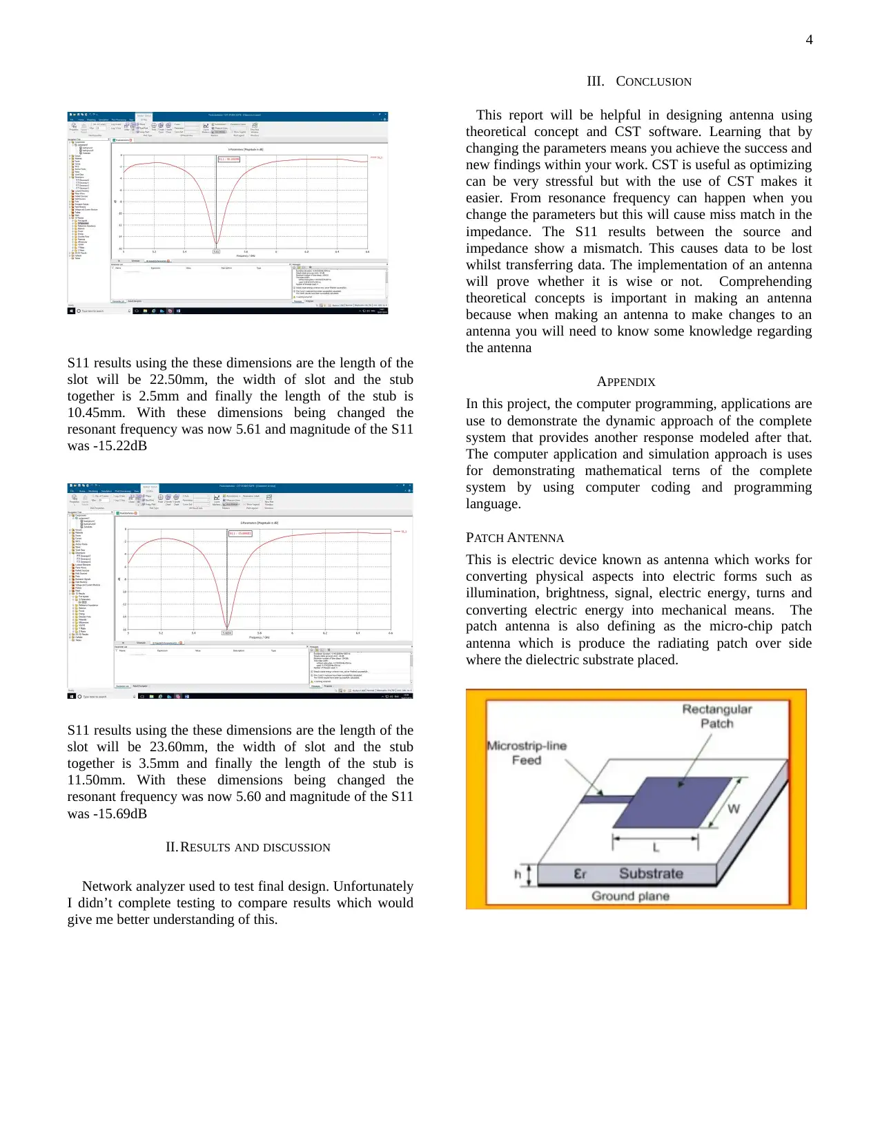
Simulation and optimization
Figure 5. The stub demminsions were 12.93 and the slot for port is 3.5mm.
This is the S parameter for figure 5
S11 results using the these dimensions are the length of the
slot will be 23.00, the width of slot and the stub together is
3.5mm and finally the length of the stub is 12.925. With
these dimensions being changed the resonant frequency was
now 5.61 and magnitude of the S11 was -14.63Db.
S11 results using the these dimensions are the length of the
slot will be 22.50mm, the width of slot and the stub
together is 3.5mm and finally the length of the stub is
10.50mm. With these dimensions being changed the
resonant frequency was now 5.60 and magnitude of the S11
was -15.34dB
comes with a casing of rubber or plastic. Then you plug it
into your device whether a receiver or transmitter that’s up
to you. The stub can be used for RF measurement devices
or calibration in RF lines. For calibration to be achieved
fully you need 50 0hms. 0 ohms and infinite impedance
using an open circuit. The magnitude of impedance is
change as the transmission line dimensions change and
connected such as the minimum voltage occurs. Ensure that
the how much the antenna transmission needs to preserve.
When you look at a quarter waves. The reflected waves
form a normal wave which can create unwanted results. The
reflected impedance can be so big however this can cause a
breakdown of dielectric material. it is observe that, there
was change in overall performance as the wave affect to
generator. In this case, there was no reflected wave produce
which is beneficially completely. That will ensure that the
priority of stub matching for operation. The line needs
match in case, the load have similar approach for
impedance. The front wave is generated through the load
releasing and there was not observing the wave generation.
The wave generation is depends on the main impedance and
characteristic impedance and the load impedance which is
ZL.
The basic designs of stub feed dipole antenna.
The design have on the CST software. We were given a
specification we had to follow. The dimensions we had to
follow the maximum dimensions couldn’t exceed 32x32
mm this was including the substrate.
Simulation and optimization
Figure 5. The stub demminsions were 12.93 and the slot for port is 3.5mm.
This is the S parameter for figure 5
S11 results using the these dimensions are the length of the
slot will be 23.00, the width of slot and the stub together is
3.5mm and finally the length of the stub is 12.925. With
these dimensions being changed the resonant frequency was
now 5.61 and magnitude of the S11 was -14.63Db.
S11 results using the these dimensions are the length of the
slot will be 22.50mm, the width of slot and the stub
together is 3.5mm and finally the length of the stub is
10.50mm. With these dimensions being changed the
resonant frequency was now 5.60 and magnitude of the S11
was -15.34dB
⊘ This is a preview!⊘
Do you want full access?
Subscribe today to unlock all pages.
Trusted by 1+ million students worldwide
4
S11 results using the these dimensions are the length of the
slot will be 22.50mm, the width of slot and the stub
together is 2.5mm and finally the length of the stub is
10.45mm. With these dimensions being changed the
resonant frequency was now 5.61 and magnitude of the S11
was -15.22dB
S11 results using the these dimensions are the length of the
slot will be 23.60mm, the width of slot and the stub
together is 3.5mm and finally the length of the stub is
11.50mm. With these dimensions being changed the
resonant frequency was now 5.60 and magnitude of the S11
was -15.69dB
II.RESULTS AND DISCUSSION
Network analyzer used to test final design. Unfortunately
I didn’t complete testing to compare results which would
give me better understanding of this.
III. CONCLUSION
This report will be helpful in designing antenna using
theoretical concept and CST software. Learning that by
changing the parameters means you achieve the success and
new findings within your work. CST is useful as optimizing
can be very stressful but with the use of CST makes it
easier. From resonance frequency can happen when you
change the parameters but this will cause miss match in the
impedance. The S11 results between the source and
impedance show a mismatch. This causes data to be lost
whilst transferring data. The implementation of an antenna
will prove whether it is wise or not. Comprehending
theoretical concepts is important in making an antenna
because when making an antenna to make changes to an
antenna you will need to know some knowledge regarding
the antenna
APPENDIX
In this project, the computer programming, applications are
use to demonstrate the dynamic approach of the complete
system that provides another response modeled after that.
The computer application and simulation approach is uses
for demonstrating mathematical terns of the complete
system by using computer coding and programming
language.
PATCH ANTENNA
This is electric device known as antenna which works for
converting physical aspects into electric forms such as
illumination, brightness, signal, electric energy, turns and
converting electric energy into mechanical means. The
patch antenna is also defining as the micro-chip patch
antenna which is produce the radiating patch over side
where the dielectric substrate placed.
S11 results using the these dimensions are the length of the
slot will be 22.50mm, the width of slot and the stub
together is 2.5mm and finally the length of the stub is
10.45mm. With these dimensions being changed the
resonant frequency was now 5.61 and magnitude of the S11
was -15.22dB
S11 results using the these dimensions are the length of the
slot will be 23.60mm, the width of slot and the stub
together is 3.5mm and finally the length of the stub is
11.50mm. With these dimensions being changed the
resonant frequency was now 5.60 and magnitude of the S11
was -15.69dB
II.RESULTS AND DISCUSSION
Network analyzer used to test final design. Unfortunately
I didn’t complete testing to compare results which would
give me better understanding of this.
III. CONCLUSION
This report will be helpful in designing antenna using
theoretical concept and CST software. Learning that by
changing the parameters means you achieve the success and
new findings within your work. CST is useful as optimizing
can be very stressful but with the use of CST makes it
easier. From resonance frequency can happen when you
change the parameters but this will cause miss match in the
impedance. The S11 results between the source and
impedance show a mismatch. This causes data to be lost
whilst transferring data. The implementation of an antenna
will prove whether it is wise or not. Comprehending
theoretical concepts is important in making an antenna
because when making an antenna to make changes to an
antenna you will need to know some knowledge regarding
the antenna
APPENDIX
In this project, the computer programming, applications are
use to demonstrate the dynamic approach of the complete
system that provides another response modeled after that.
The computer application and simulation approach is uses
for demonstrating mathematical terns of the complete
system by using computer coding and programming
language.
PATCH ANTENNA
This is electric device known as antenna which works for
converting physical aspects into electric forms such as
illumination, brightness, signal, electric energy, turns and
converting electric energy into mechanical means. The
patch antenna is also defining as the micro-chip patch
antenna which is produce the radiating patch over side
where the dielectric substrate placed.
Paraphrase This Document
Need a fresh take? Get an instant paraphrase of this document with our AI Paraphraser
5
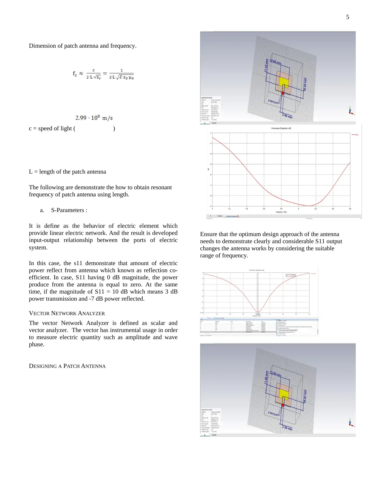
Dimension of patch antenna and frequency.
c = speed of light ( )
L = length of the patch antenna
The following are demonstrate the how to obtain resonant
frequency of patch antenna using length.
a. S-Parameters :
It is define as the behavior of electric element which
provide linear electric network. And the result is developed
input-output relationship between the ports of electric
system.
In this case, the s11 demonstrate that amount of electric
power reflect from antenna which known as reflection co-
efficient. In case, S11 having 0 dB magnitude, the power
produce from the antenna is equal to zero. At the same
time, if the magnitude of S11 = 10 dB which means 3 dB
power transmission and -7 dB power reflected.
VECTOR NETWORK ANALYZER
The vector Network Analyzer is defined as scalar and
vector analyzer. The vector has instrumental usage in order
to measure electric quantity such as amplitude and wave
phase.
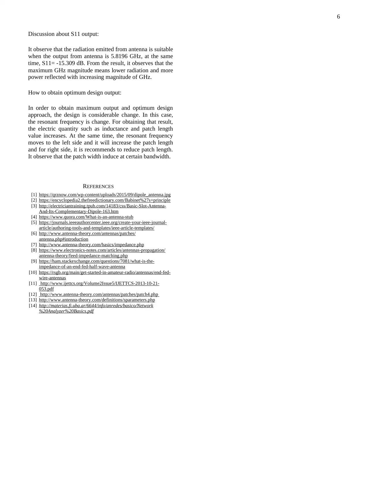
DESIGNING A PATCH ANTENNA
Ensure that the optimum design approach of the antenna
needs to demonstrate clearly and considerable S11 output
changes the antenna works by considering the suitable
range of frequency.
Dimension of patch antenna and frequency.
c = speed of light ( )
L = length of the patch antenna
The following are demonstrate the how to obtain resonant
frequency of patch antenna using length.
a. S-Parameters :
It is define as the behavior of electric element which
provide linear electric network. And the result is developed
input-output relationship between the ports of electric
system.
In this case, the s11 demonstrate that amount of electric
power reflect from antenna which known as reflection co-
efficient. In case, S11 having 0 dB magnitude, the power
produce from the antenna is equal to zero. At the same
time, if the magnitude of S11 = 10 dB which means 3 dB
power transmission and -7 dB power reflected.
VECTOR NETWORK ANALYZER
The vector Network Analyzer is defined as scalar and
vector analyzer. The vector has instrumental usage in order
to measure electric quantity such as amplitude and wave
phase.
DESIGNING A PATCH ANTENNA
Ensure that the optimum design approach of the antenna
needs to demonstrate clearly and considerable S11 output
changes the antenna works by considering the suitable
range of frequency.
6
Discussion about S11 output:
It observe that the radiation emitted from antenna is suitable
when the output from antenna is 5.8196 GHz, at the same
time, S11= -15.309 dB. From the result, it observes that the
maximum GHz magnitude means lower radiation and more
power reflected with increasing magnitude of GHz.
How to obtain optimum design output:
In order to obtain maximum output and optimum design
approach, the design is considerable change. In this case,
the resonant frequency is change. For obtaining that result,
the electric quantity such as inductance and patch length
value increases. At the same time, the resonant frequency
moves to the left side and it will increase the patch length
and for right side, it is recommends to reduce patch length.
It observe that the patch width induce at certain bandwidth.
REFERENCES
[1] https://qrznow.com/wp-content/uploads/2015/09/dipole_antenna.jpg
[2] https://encyclopedia2.thefreedictionary.com/Babinet%27s+principle
[3] http://electriciantraining.tpub.com/14183/css/Basic-Slot-Antenna-
And-Its-Complementary-Dipole-163.htm
[4] https://www.quora.com/What-is-an-antenna-stub
[5] https://journals.ieeeauthorcenter.ieee.org/create-your-ieee-journal-
article/authoring-tools-and-templates/ieee-article-templates/
[6] http://www.antenna-theory.com/antennas/patches/
antenna.php#introduction
[7] http://www.antenna-theory.com/basics/impedance.php
[8] https://www.electronics-notes.com/articles/antennas-propagation/
antenna-theory/feed-impedance-matching.php
[9] https://ham.stackexchange.com/questions/7081/what-is-the-
impedance-of-an-end-fed-half-wave-antenna
[10] https://rsgb.org/main/get-started-in-amateur-radio/antennas/end-fed-
wire-antennas
[11] http://www.ijettcs.org/Volume2Issue5/IJETTCS-2013-10-21-
053.pdf
[12] http://www.antenna-theory.com/antennas/patches/patch4.php
[13] http://www.antenna-theory.com/definitions/sparameters.php
[14] http://materias.fi.uba.ar/6644/info/anredes/basico/Network
%20Analyzer%20Basics.pdf
⊘ This is a preview!⊘
Do you want full access?
Subscribe today to unlock all pages.
Trusted by 1+ million students worldwide
1 out of 6
Related Documents


Your All-in-One AI-Powered Toolkit for Academic Success.
+13062052269
info@desklib.com
Available 24*7 on WhatsApp / Email
![[object Object]](/_next/static/media/star-bottom.7253800d.svg)
Unlock your academic potential
Copyright © 2020–2026 A2Z Services. All Rights Reserved. Developed and managed by ZUCOL.