LAN Network Design and Implementation for Football Field Marketing Ltd
VerifiedAdded on 2024/06/27
|45
|4502
|135
AI Summary
This report details the design and implementation of a Local Area Network (LAN) infrastructure for Football Field Marketing Ltd, a company operating in the sales and marketing sector. The report covers the design of the LAN topology, the selection and configuration of network components, the implementation of network security measures, and the testing and troubleshooting of the network. The report also includes a critical evaluation of the performance of the LAN.
Contribute Materials
Your contribution can guide someone’s learning journey. Share your
documents today.
LOCAL AREA NETWORKING
TECHNOLOGIES
1
TECHNOLOGIES
1
Secure Best Marks with AI Grader
Need help grading? Try our AI Grader for instant feedback on your assignments.

Table of Contents
LO2 Be able to design LAN infrastructures............................................................................................5
A.C 2.1 Design a LAN infrastructure for the company which will facilitate all of their requirements 5
A.C 2.2 Critically evaluate the suitability of LAN components...........................................................7
LO3. Be able to implement LAN infrastructures..................................................................................14
A.C 3.1 Builds and configures a LAN (including services) to meet a given requirement..................14
A.C 3.2 Implements network security on a LAN...............................................................................22
A.C 3.3 Critically reviews and tests a LAN........................................................................................28
LO4. Be able to manage LAN infrastructures.......................................................................................34
A.C 4.1 Critically discusses how this LAN infrastructure will be monitored and managed (via
troubleshooting) if there is an issue during the post-implementation period.................................34
A.C 4.2 Resolves LAN issues to improve security, reliability and performance................................38
A.C 4.3 Critically evaluate the performance of a LAN......................................................................39
References:..........................................................................................................................................45
2
List of Figures
s
Figure 1 LAN network infrastructure 6
Figure 2 Ring Topology..........................................................................................................................8
Figure 3 Mesh Topology........................................................................................................................9
Figure 4 Tree network - hybrid topology.............................................................................................10
Figure 5 Ring-Star network - hybrid topology......................................................................................10
Figure 6 Bus Topology.........................................................................................................................11
Figure 7 Star Topology.........................................................................................................................12
Figure 8 Cellular topology....................................................................................................................13
Figure 9: LAN network solution...........................................................................................................15
Figure 10: Proposed LAN Network Metadata 1...................................................................................16
Figure 11: Proposed LAN Network Metadata 2...................................................................................17
Figure 12: Proposed LAN Network Metadata 3...................................................................................18
Figure 13: Proposed LAN Network Metadata 4...................................................................................18
Figure 14: Proposed LAN Network HTTP Server Domain.....................................................................19
Figure 15: Require LAN network proposal...........................................................................................19
Figure 16: Access of Telnet in the LAN network..................................................................................20
Figure 17: LAN network server such as DNS server.............................................................................20
Figure 18: LAN network server such as DHCP server...........................................................................21
Figure 19: Implementation of VLAN trunking as security purpose......................................................22
Figure 20: Implementation of Access control lists as security purpose...............................................23
Figure 21: Implementation of Router configuration as security purpose............................................24
Figure 22: Router configuration part 1................................................................................................25
Figure 23: Router configuration part 2................................................................................................26
Figure 24: Router configuration part 3................................................................................................27
Figure 25: Router configuration part 4................................................................................................27
Figure 26: Test case 1..........................................................................................................................29
Figure 27: Test case 2..........................................................................................................................30
Figure 28: Test case 3..........................................................................................................................30
Figure 29: Test case 4..........................................................................................................................31
Figure 30: Test case 5..........................................................................................................................31
Figure 31: Test case 6..........................................................................................................................32
Figure 32: : Test case 7........................................................................................................................32
3
Figure 33: Test case 8.........................................................................................................................33
Figure 34: Testing of Paring command 1.............................................................................................35
Figure 35: Testing of Paring command 2.............................................................................................35
Figure 36: Testing of Ping command 1.................................................................................................36
Figure 37: Testing of Ping command 2.................................................................................................36
Figure 38: Testing of Ping command 3.................................................................................................37
Figure 39: Testing of Ping command 4.................................................................................................37
Figure 40: Ping command test 1..........................................................................................................39
Figure 41: Ping command test 2..........................................................................................................40
Figure 42: Ping command test 3..........................................................................................................40
Figure 43: Network design...................................................................................................................41
Figure 44: PDU list showing the failed connection between departments..........................................42
Figure 45: PDU list showing success connection between departments.............................................42
Figure 46: Ping command test 1..........................................................................................................42
Figure 47: Ping command test 2..........................................................................................................43
Figure 48: Ping command test 3..........................................................................................................43
4
Secure Best Marks with AI Grader
Need help grading? Try our AI Grader for instant feedback on your assignments.
LO2 Be able to design LAN infrastructures
A.C 2.1 Design a LAN infrastructure for the company which will facilitate all of their
requirements
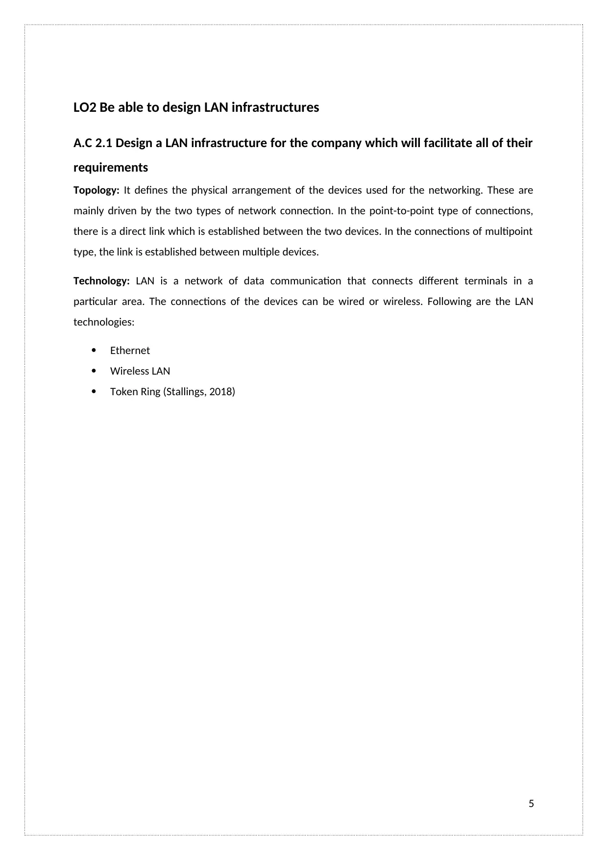
Topology: It defines the physical arrangement of the devices used for the networking. These are
mainly driven by the two types of network connection. In the point-to-point type of connections,
there is a direct link which is established between the two devices. In the connections of multipoint
type, the link is established between multiple devices.
Technology: LAN is a network of data communication that connects different terminals in a
particular area. The connections of the devices can be wired or wireless. Following are the LAN
technologies:
Ethernet
Wireless LAN
Token Ring (Stallings, 2018)
5
A.C 2.1 Design a LAN infrastructure for the company which will facilitate all of their
requirements
Topology: It defines the physical arrangement of the devices used for the networking. These are
mainly driven by the two types of network connection. In the point-to-point type of connections,
there is a direct link which is established between the two devices. In the connections of multipoint
type, the link is established between multiple devices.
Technology: LAN is a network of data communication that connects different terminals in a
particular area. The connections of the devices can be wired or wireless. Following are the LAN
technologies:
Ethernet
Wireless LAN
Token Ring (Stallings, 2018)
5
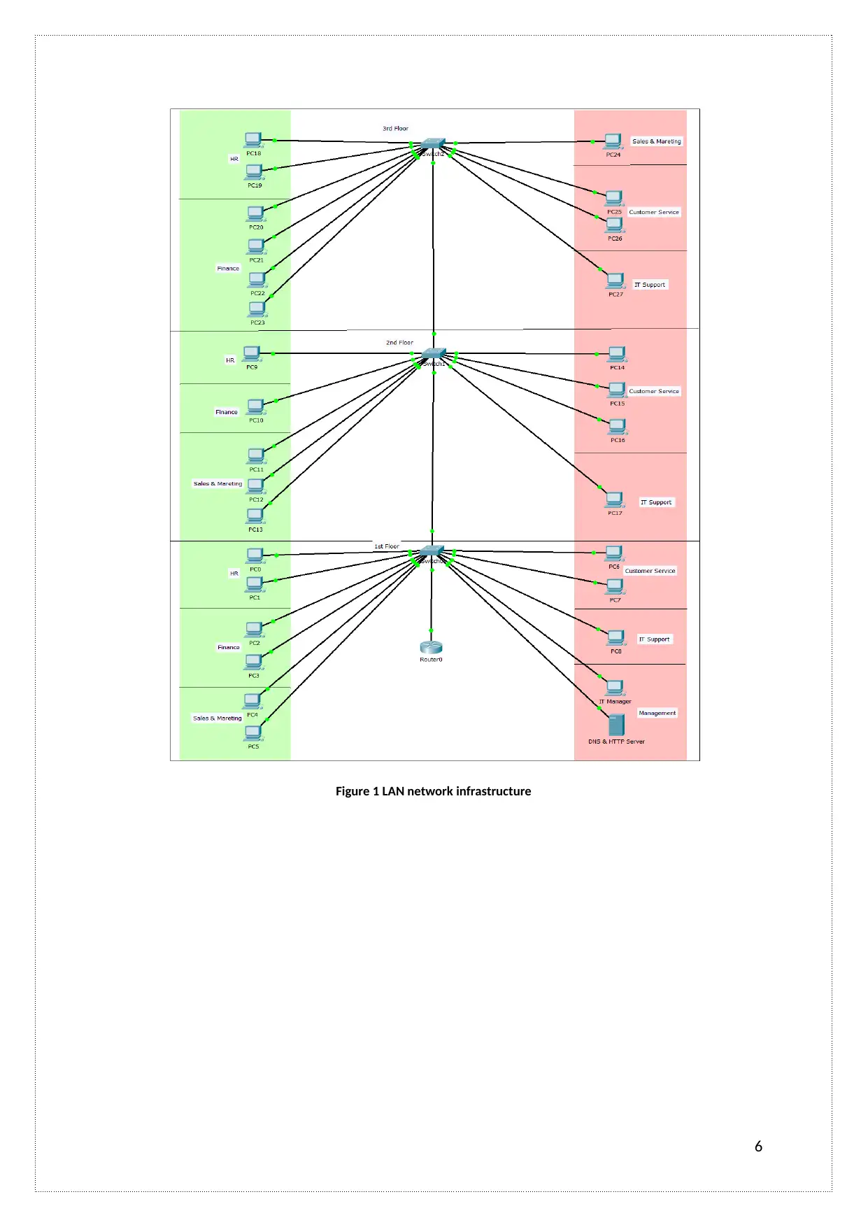
Figure 1 LAN network infrastructure
6
6
A.C 2.2 Critically evaluate the suitability of LAN components
Following are the components of the LAN:
1. Switch: This is a fundamental part of the network. They allow the nodes to communicate
with other nodes in an efficient and smooth manner. The switches in the LAN provide a
separate connection to each node in the internal network of the company. The switch then
creates a series of a network consisting of two devices.
2. Routers: Routers are the network devices that forward the packets of data among the
computer networks. The routers direct the functions on the internet. The data sent on the
internet is in the form of data packets. The routers forward these packets from routers to
other routers in the network. These routers are attached with many data lines of various
networks. The most common type of network is small office and home routers. These simply
forwards the IP packets.
3. Hubs: A hub is also called as a network hub. It acts as a common point of connection of the
devices that are used to connect with the segments of the LAN. A hub consists of many
ports. Whenever a packet comes at any of the port, it gets copied to other ports as well so as
to allow segments of LAN to see the packets. It acts as a central connection of all the
equipment of the network.
The Topologies of the LAN are
There are following types of LAN topologies:
1. Ring Topology
2. Mesh Topology
3. Hybrid Topology
4. Bus Topology
5. Star Topology
6. Cellular Topology
7
Paraphrase This Document
Need a fresh take? Get an instant paraphrase of this document with our AI Paraphraser
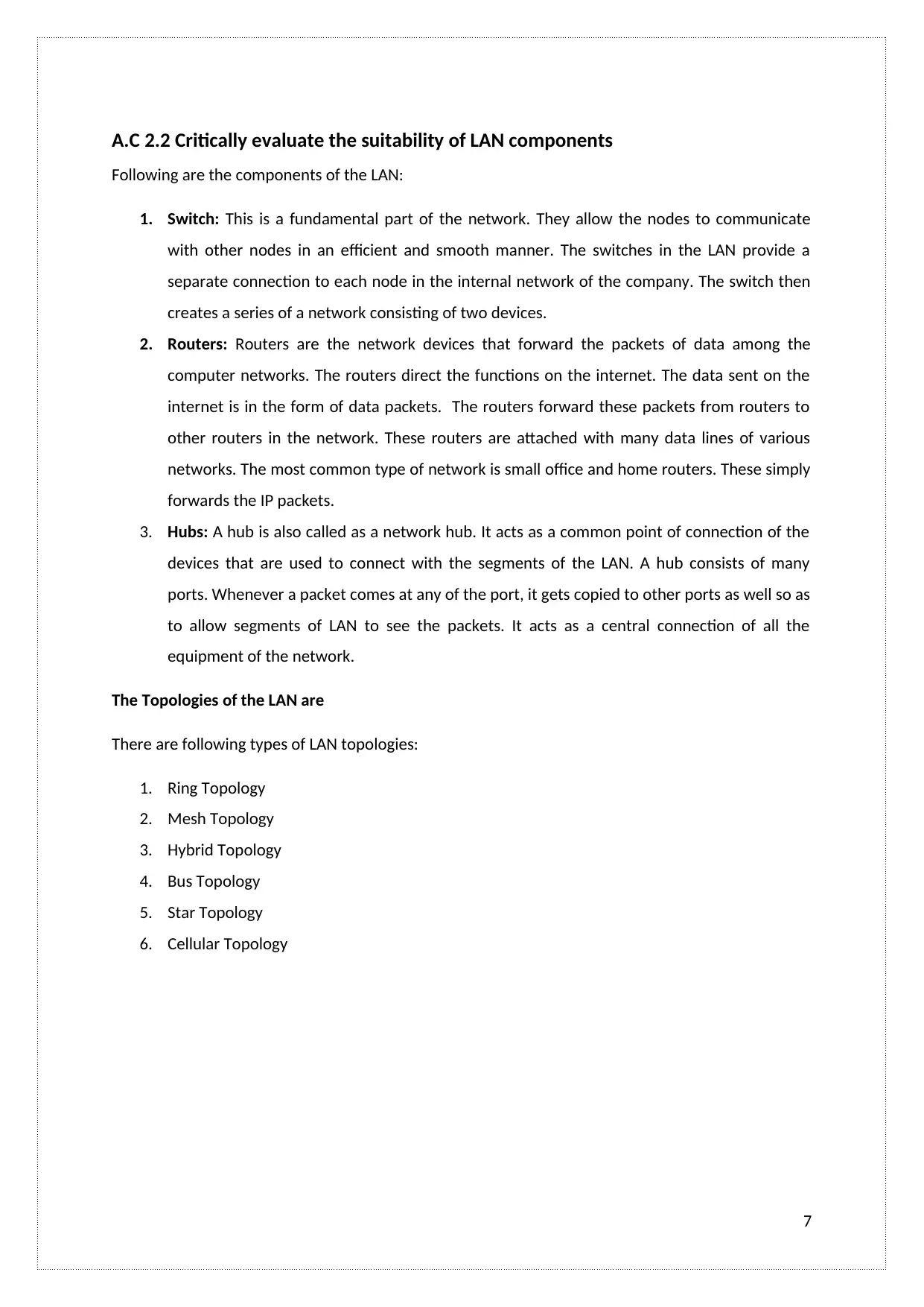
Ring Topology:
In this type of topology, the addresses do not match with each other so the nodes regenerate those
messages and then sends them. Then if the address gets matches, the node will accept the message
and then replies back to the real sender of the message. In the beginning, this topology was easy to
install but these require large media than other systems as the loops are needed to be closed. After
installing the ring, it gets more difficult to reconfigure them.
Advantages:
1. It is simple to troubleshoot them.
2. The workstations which get troubled gets identified easily in this topology.
Disadvantages:
1. It is difficult to reconfigure and install.
2. Any media failure can cause the whole network to fail.
Figure 2 Ring Topology
8
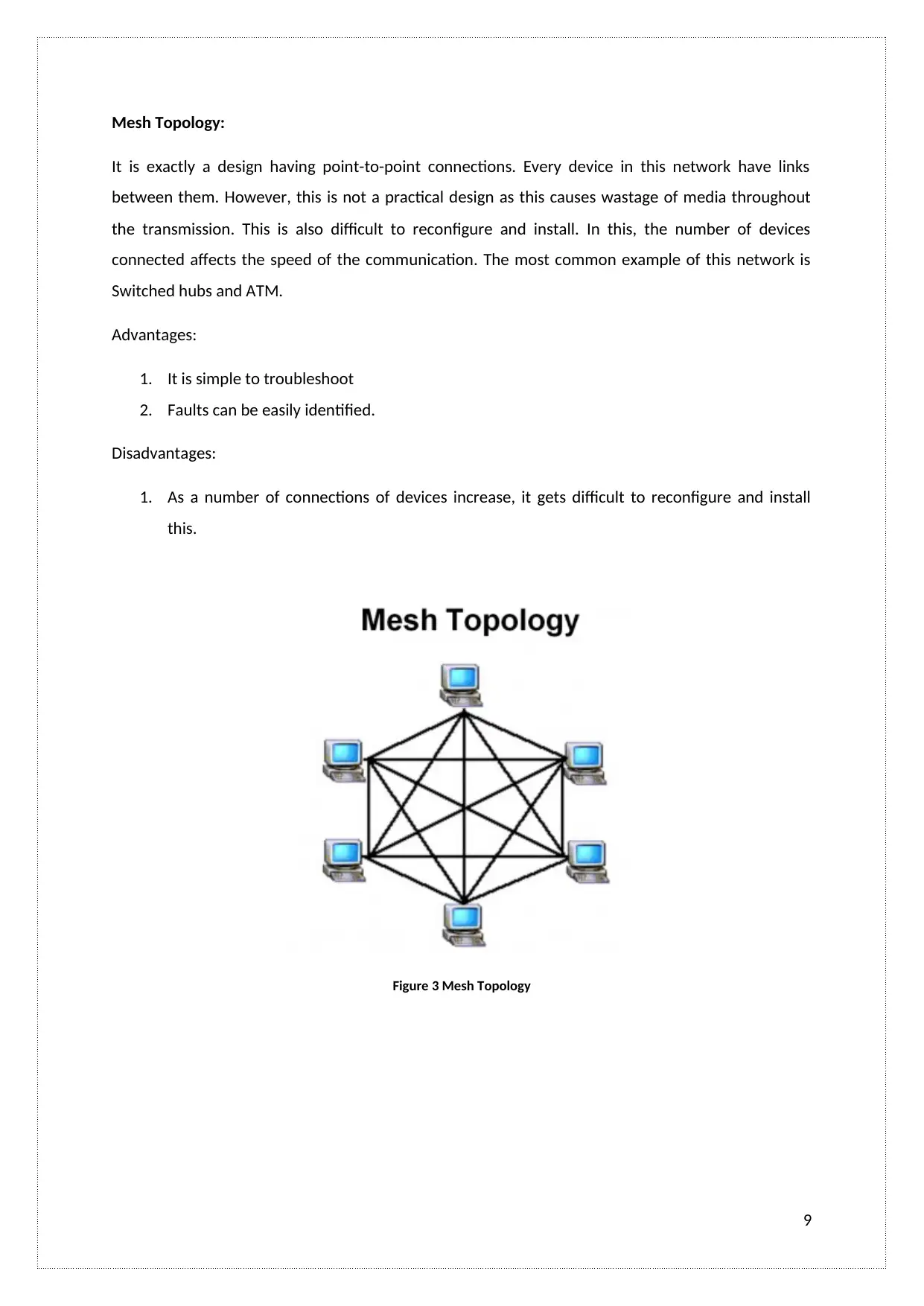
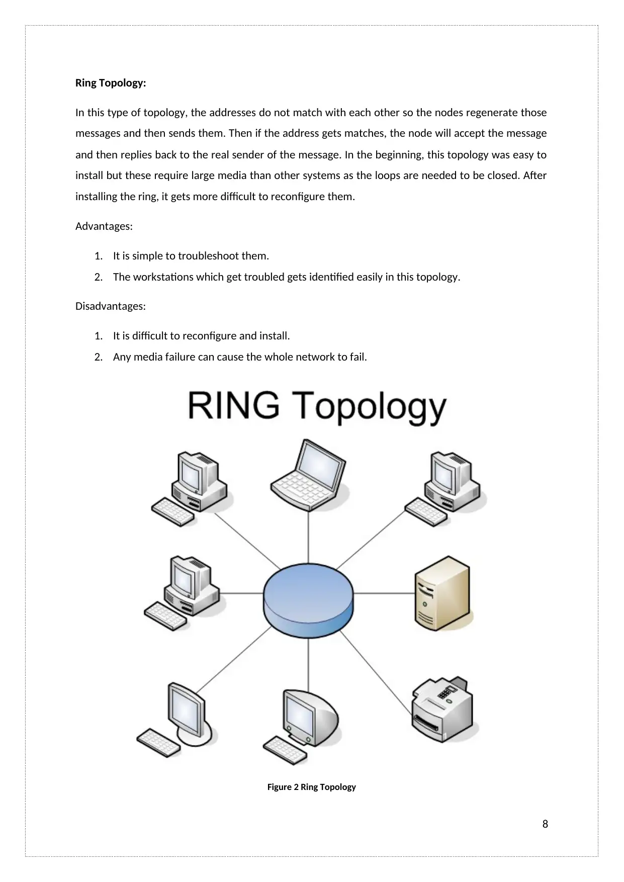
Mesh Topology:
It is exactly a design having point-to-point connections. Every device in this network have links
between them. However, this is not a practical design as this causes wastage of media throughout
the transmission. This is also difficult to reconfigure and install. In this, the number of devices
connected affects the speed of the communication. The most common example of this network is
Switched hubs and ATM.
Advantages:
1. It is simple to troubleshoot
2. Faults can be easily identified.
Disadvantages:
1. As a number of connections of devices increase, it gets difficult to reconfigure and install
this.
Figure 3 Mesh Topology
9
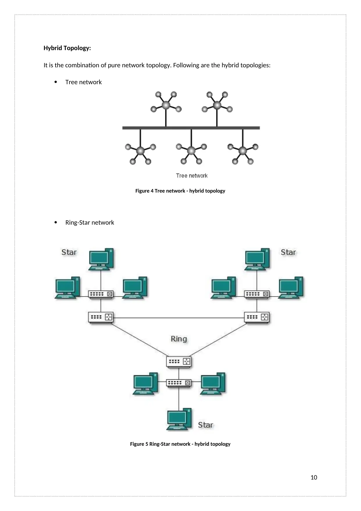
Hybrid Topology:
It is the combination of pure network topology. Following are the hybrid topologies:
Tree network
Figure 4 Tree network - hybrid topology
Ring-Star network
Figure 5 Ring-Star network - hybrid topology
10
It is the combination of pure network topology. Following are the hybrid topologies:
Tree network
Figure 4 Tree network - hybrid topology
Ring-Star network
Figure 5 Ring-Star network - hybrid topology
10
Secure Best Marks with AI Grader
Need help grading? Try our AI Grader for instant feedback on your assignments.
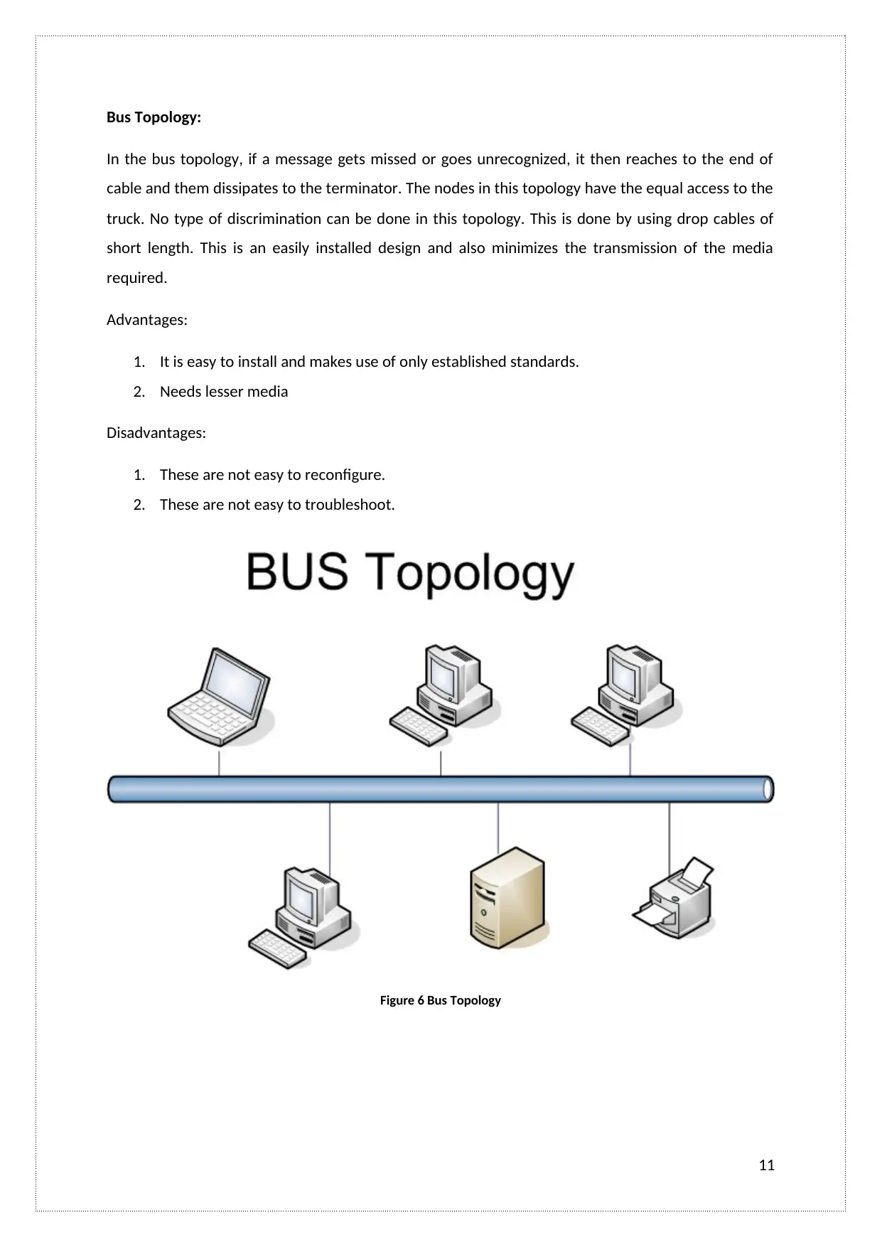
Bus Topology:
In the bus topology, if a message gets missed or goes unrecognized, it then reaches to the end of
cable and them dissipates to the terminator. The nodes in this topology have the equal access to the
truck. No type of discrimination can be done in this topology. This is done by using drop cables of
short length. This is an easily installed design and also minimizes the transmission of the media
required.
Advantages:
1. It is easy to install and makes use of only established standards.
2. Needs lesser media
Disadvantages:
1. These are not easy to reconfigure.
2. These are not easy to troubleshoot.
Figure 6 Bus Topology
11
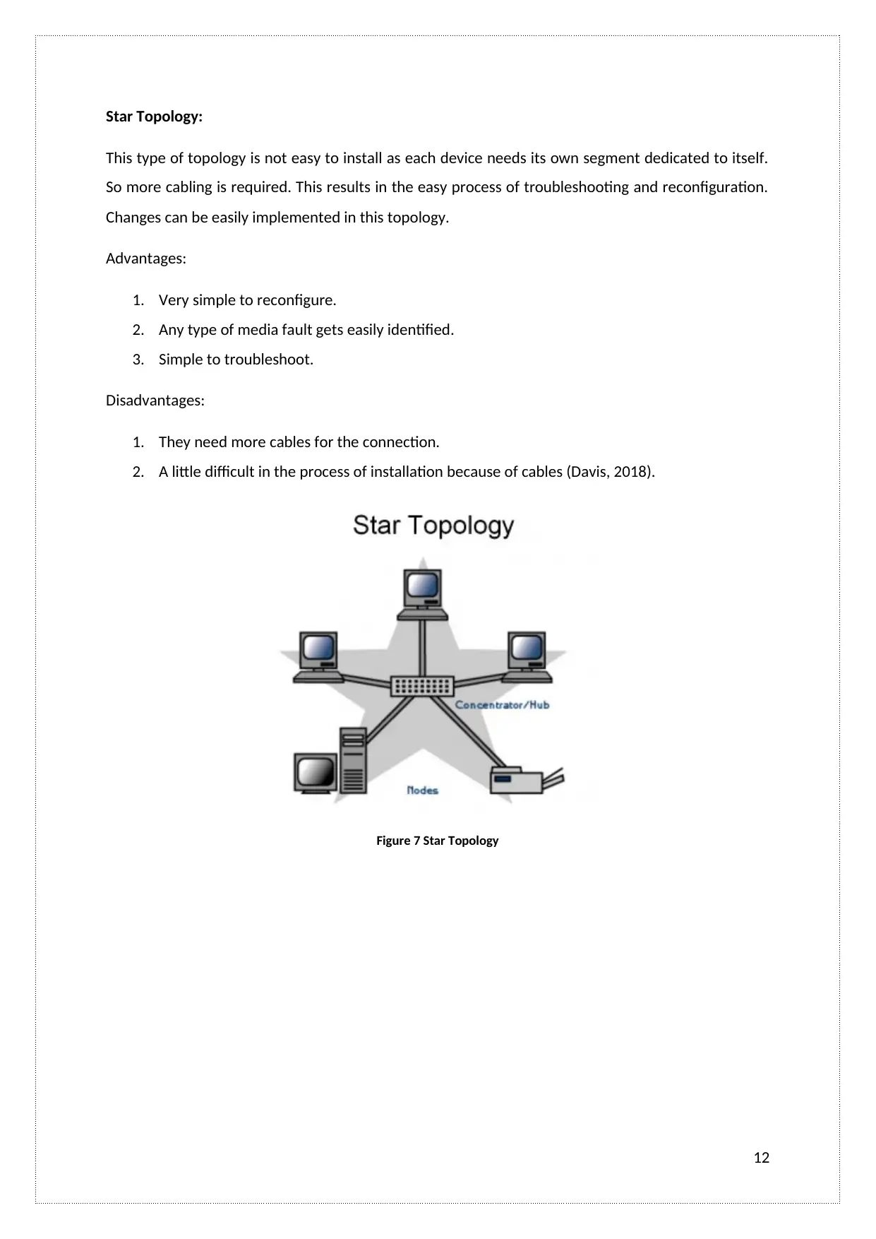
Star Topology:
This type of topology is not easy to install as each device needs its own segment dedicated to itself.
So more cabling is required. This results in the easy process of troubleshooting and reconfiguration.
Changes can be easily implemented in this topology.
Advantages:
1. Very simple to reconfigure.
2. Any type of media fault gets easily identified.
3. Simple to troubleshoot.
Disadvantages:
1. They need more cables for the connection.
2. A little difficult in the process of installation because of cables (Davis, 2018).
Figure 7 Star Topology
12
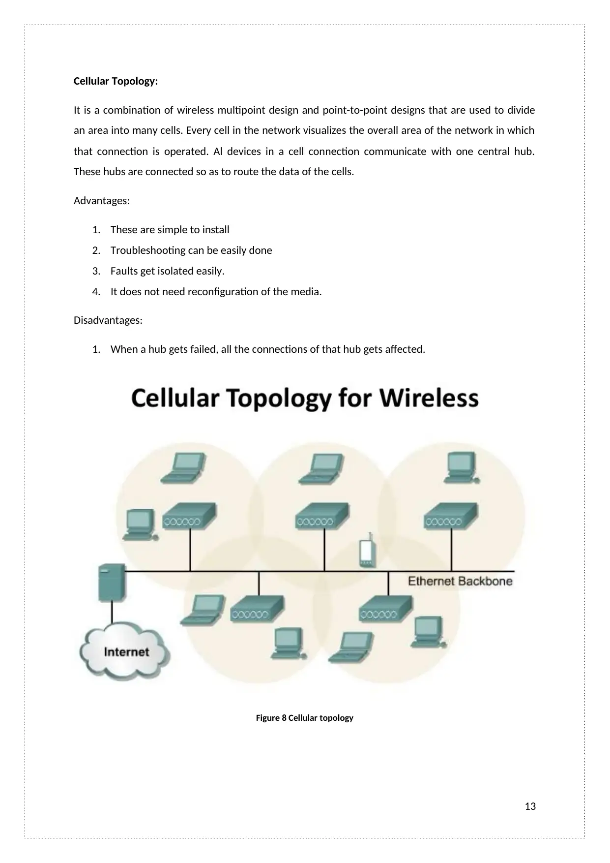
Cellular Topology:
It is a combination of wireless multipoint design and point-to-point designs that are used to divide
an area into many cells. Every cell in the network visualizes the overall area of the network in which
that connection is operated. Al devices in a cell connection communicate with one central hub.
These hubs are connected so as to route the data of the cells.
Advantages:
1. These are simple to install
2. Troubleshooting can be easily done
3. Faults get isolated easily.
4. It does not need reconfiguration of the media.
Disadvantages:
1. When a hub gets failed, all the connections of that hub gets affected.
Figure 8 Cellular topology
13
Paraphrase This Document
Need a fresh take? Get an instant paraphrase of this document with our AI Paraphraser
LO3. Be able to implement LAN infrastructures
A.C 3.1 Builds and configures a LAN (including services) to meet a given
requirement
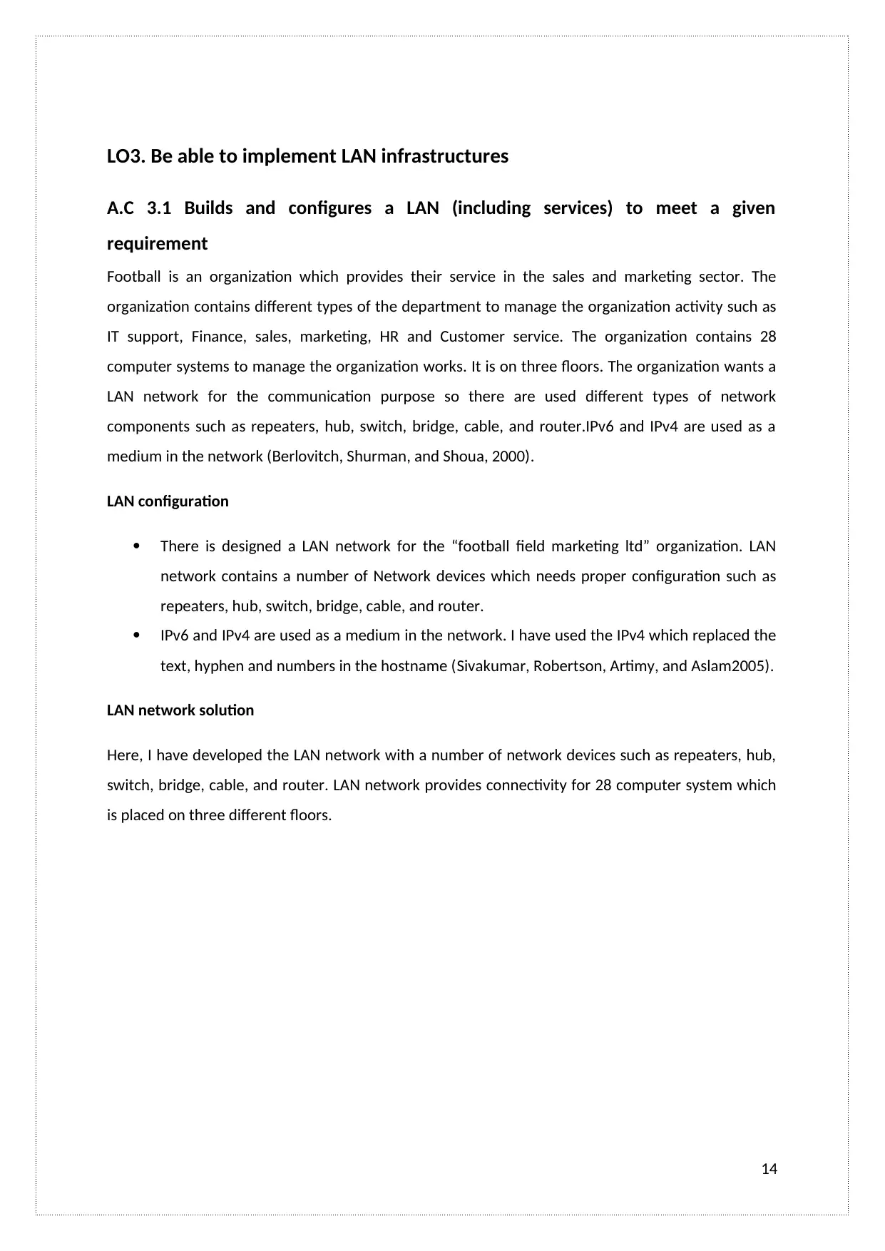
Football is an organization which provides their service in the sales and marketing sector. The
organization contains different types of the department to manage the organization activity such as
IT support, Finance, sales, marketing, HR and Customer service. The organization contains 28
computer systems to manage the organization works. It is on three floors. The organization wants a
LAN network for the communication purpose so there are used different types of network
components such as repeaters, hub, switch, bridge, cable, and router.IPv6 and IPv4 are used as a
medium in the network (Berlovitch, Shurman, and Shoua, 2000).
LAN configuration
There is designed a LAN network for the “football field marketing ltd” organization. LAN
network contains a number of Network devices which needs proper configuration such as
repeaters, hub, switch, bridge, cable, and router.
IPv6 and IPv4 are used as a medium in the network. I have used the IPv4 which replaced the
text, hyphen and numbers in the hostname (Sivakumar, Robertson, Artimy, and Aslam2005).
LAN network solution
Here, I have developed the LAN network with a number of network devices such as repeaters, hub,
switch, bridge, cable, and router. LAN network provides connectivity for 28 computer system which
is placed on three different floors.
14
A.C 3.1 Builds and configures a LAN (including services) to meet a given
requirement
Football is an organization which provides their service in the sales and marketing sector. The
organization contains different types of the department to manage the organization activity such as
IT support, Finance, sales, marketing, HR and Customer service. The organization contains 28
computer systems to manage the organization works. It is on three floors. The organization wants a
LAN network for the communication purpose so there are used different types of network
components such as repeaters, hub, switch, bridge, cable, and router.IPv6 and IPv4 are used as a
medium in the network (Berlovitch, Shurman, and Shoua, 2000).
LAN configuration
There is designed a LAN network for the “football field marketing ltd” organization. LAN
network contains a number of Network devices which needs proper configuration such as
repeaters, hub, switch, bridge, cable, and router.
IPv6 and IPv4 are used as a medium in the network. I have used the IPv4 which replaced the
text, hyphen and numbers in the hostname (Sivakumar, Robertson, Artimy, and Aslam2005).
LAN network solution
Here, I have developed the LAN network with a number of network devices such as repeaters, hub,
switch, bridge, cable, and router. LAN network provides connectivity for 28 computer system which
is placed on three different floors.
14
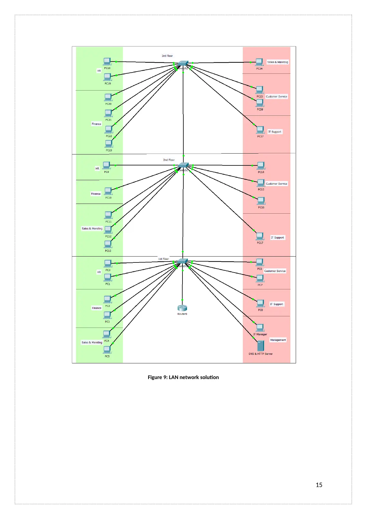
Figure 9: LAN network solution
15
15
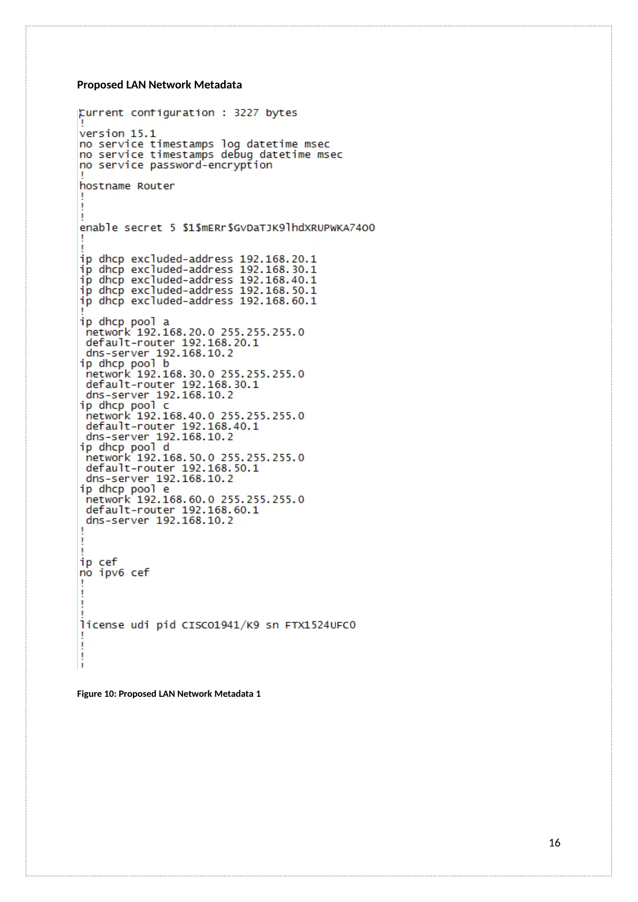
Proposed LAN Network Metadata
Figure 10: Proposed LAN Network Metadata 1
16
Figure 10: Proposed LAN Network Metadata 1
16
Secure Best Marks with AI Grader
Need help grading? Try our AI Grader for instant feedback on your assignments.
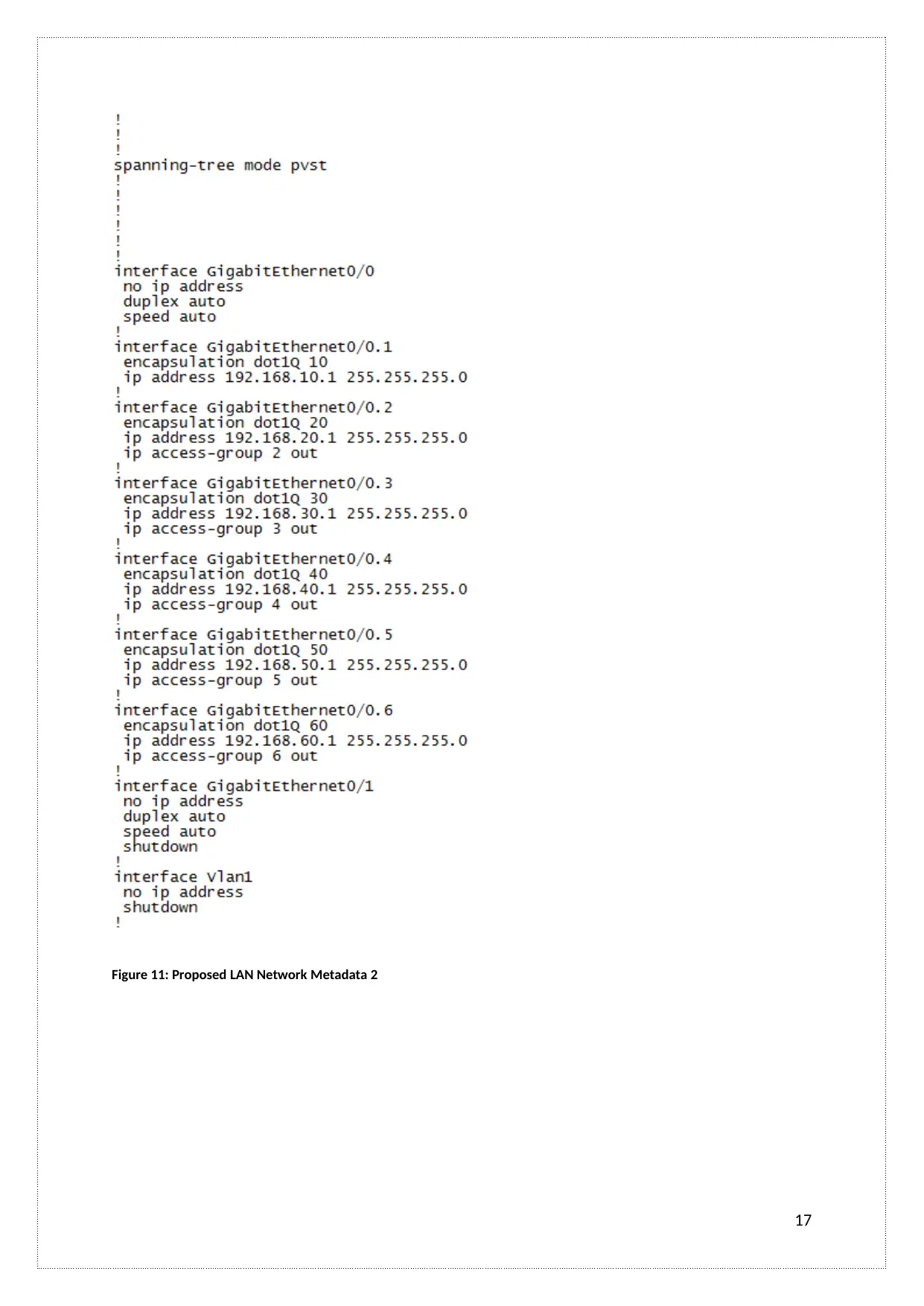
Figure 11: Proposed LAN Network Metadata 2
17
17
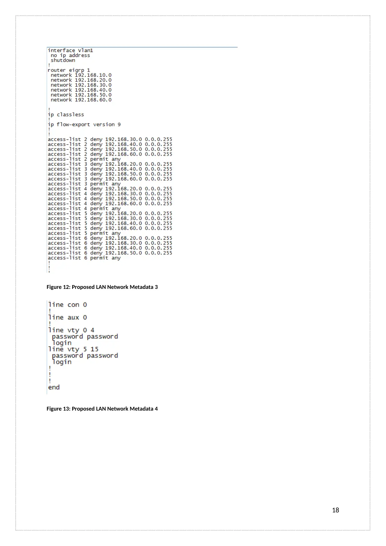
Figure 12: Proposed LAN Network Metadata 3
Figure 13: Proposed LAN Network Metadata 4
18
Figure 13: Proposed LAN Network Metadata 4
18
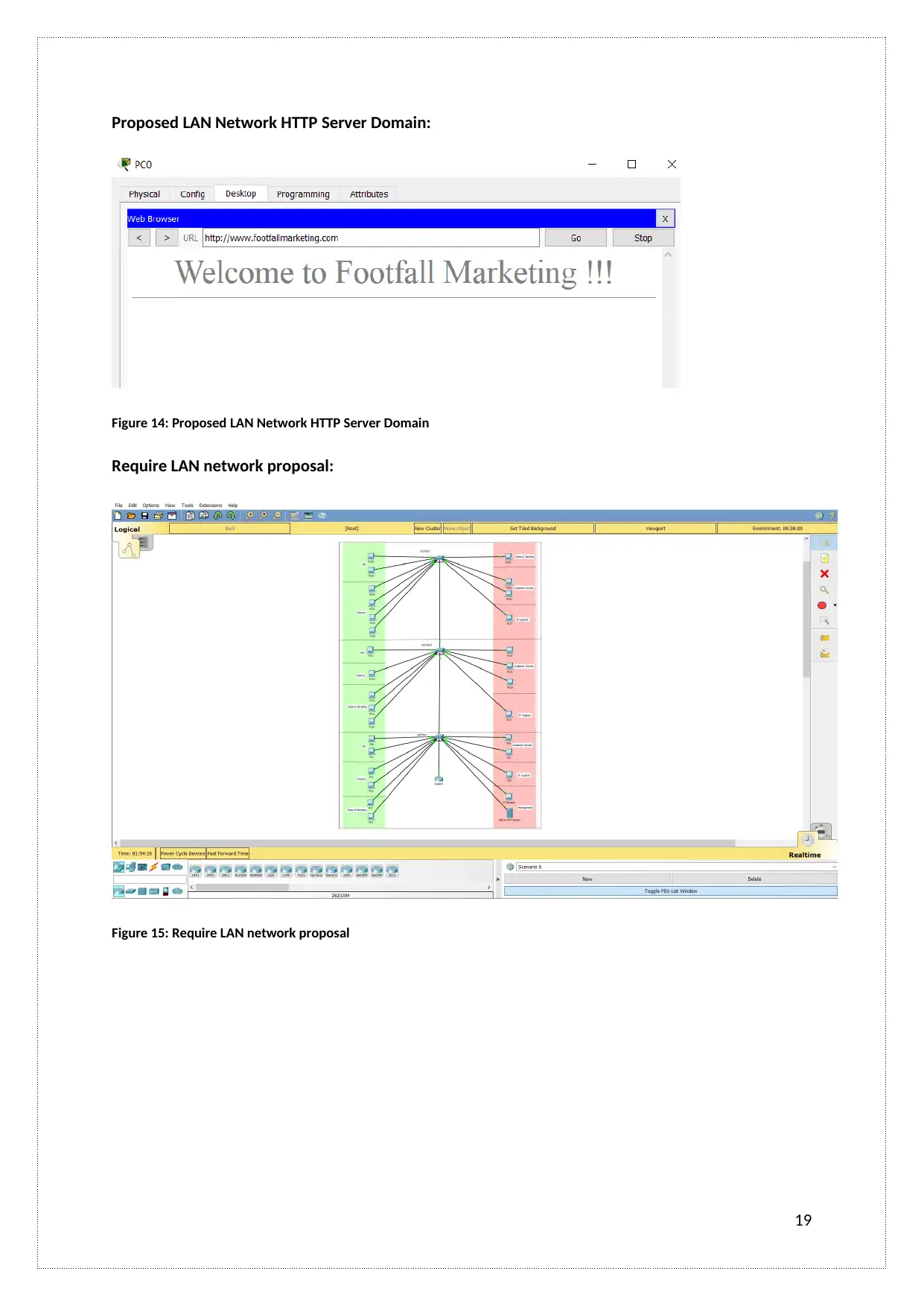
Proposed LAN Network HTTP Server Domain:
Figure 14: Proposed LAN Network HTTP Server Domain
Require LAN network proposal:
Figure 15: Require LAN network proposal
19
Figure 14: Proposed LAN Network HTTP Server Domain
Require LAN network proposal:
Figure 15: Require LAN network proposal
19
Paraphrase This Document
Need a fresh take? Get an instant paraphrase of this document with our AI Paraphraser
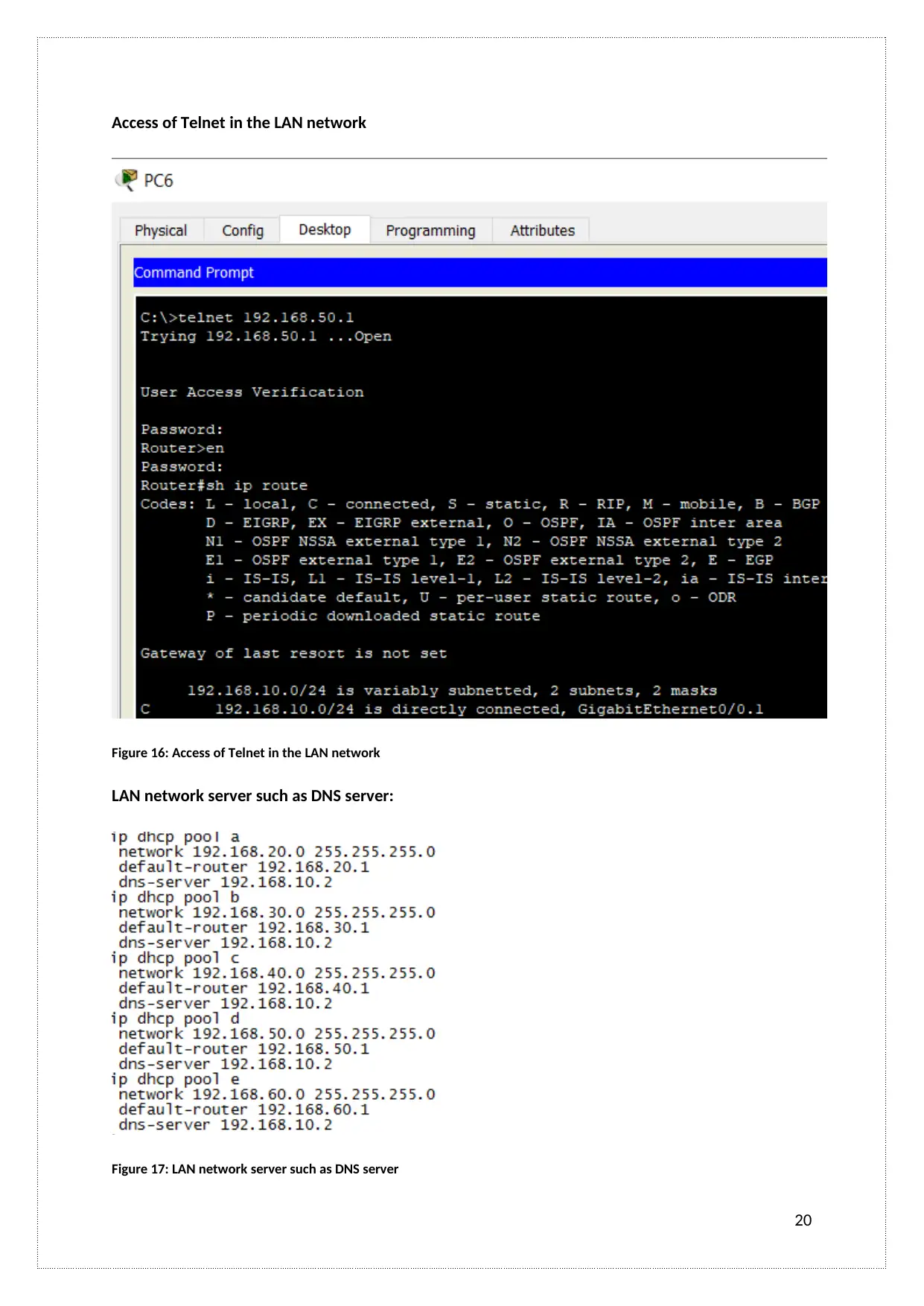
Access of Telnet in the LAN network
Figure 16: Access of Telnet in the LAN network
LAN network server such as DNS server:
Figure 17: LAN network server such as DNS server
20
Figure 16: Access of Telnet in the LAN network
LAN network server such as DNS server:
Figure 17: LAN network server such as DNS server
20
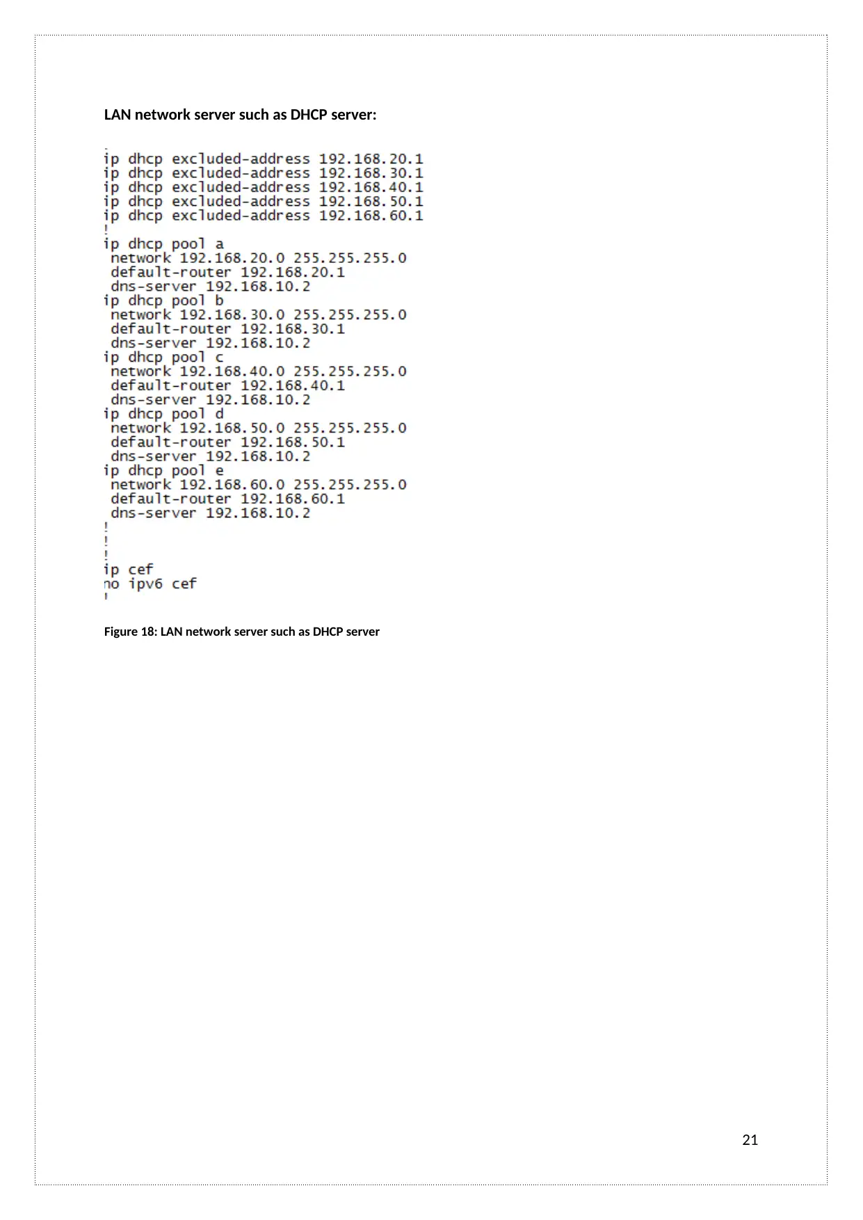
LAN network server such as DHCP server:
Figure 18: LAN network server such as DHCP server
21
Figure 18: LAN network server such as DHCP server
21
A.C 3.2 Implements network security on a LAN
The organization wants a long-term network for the communication and sharing purpose so there is
a need for the network security. Customer or user shares their important information. VLAN
trunking, router security, and Access lists are implemented in the Network for security purpose. It
provides network security when the packet transmission from source to destination.
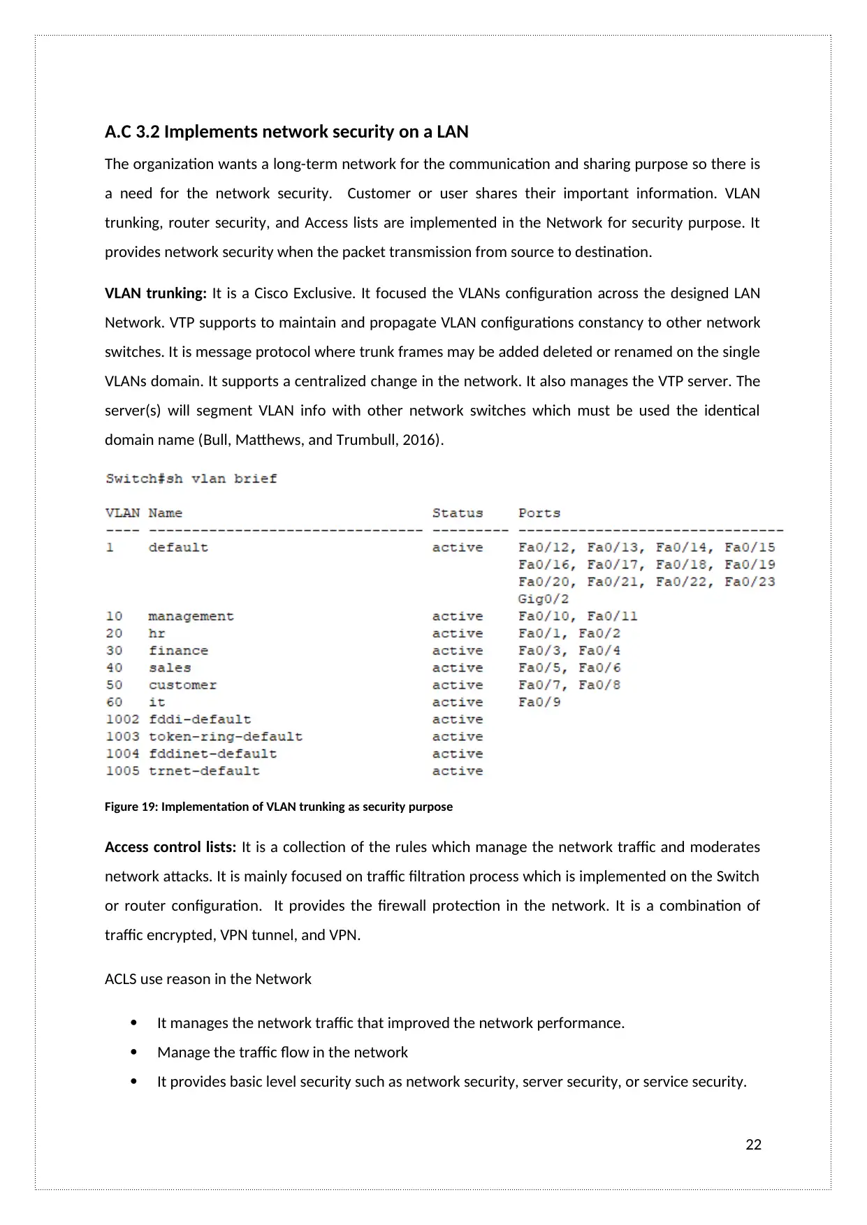
VLAN trunking: It is a Cisco Exclusive. It focused the VLANs configuration across the designed LAN
Network. VTP supports to maintain and propagate VLAN configurations constancy to other network
switches. It is message protocol where trunk frames may be added deleted or renamed on the single
VLANs domain. It supports a centralized change in the network. It also manages the VTP server. The
server(s) will segment VLAN info with other network switches which must be used the identical
domain name (Bull, Matthews, and Trumbull, 2016).
Figure 19: Implementation of VLAN trunking as security purpose
Access control lists: It is a collection of the rules which manage the network traffic and moderates
network attacks. It is mainly focused on traffic filtration process which is implemented on the Switch
or router configuration. It provides the firewall protection in the network. It is a combination of
traffic encrypted, VPN tunnel, and VPN.
ACLS use reason in the Network
It manages the network traffic that improved the network performance.
Manage the traffic flow in the network
It provides basic level security such as network security, server security, or service security.
22
The organization wants a long-term network for the communication and sharing purpose so there is
a need for the network security. Customer or user shares their important information. VLAN
trunking, router security, and Access lists are implemented in the Network for security purpose. It
provides network security when the packet transmission from source to destination.
VLAN trunking: It is a Cisco Exclusive. It focused the VLANs configuration across the designed LAN
Network. VTP supports to maintain and propagate VLAN configurations constancy to other network
switches. It is message protocol where trunk frames may be added deleted or renamed on the single
VLANs domain. It supports a centralized change in the network. It also manages the VTP server. The
server(s) will segment VLAN info with other network switches which must be used the identical
domain name (Bull, Matthews, and Trumbull, 2016).
Figure 19: Implementation of VLAN trunking as security purpose
Access control lists: It is a collection of the rules which manage the network traffic and moderates
network attacks. It is mainly focused on traffic filtration process which is implemented on the Switch
or router configuration. It provides the firewall protection in the network. It is a combination of
traffic encrypted, VPN tunnel, and VPN.
ACLS use reason in the Network
It manages the network traffic that improved the network performance.
Manage the traffic flow in the network
It provides basic level security such as network security, server security, or service security.
22
Secure Best Marks with AI Grader
Need help grading? Try our AI Grader for instant feedback on your assignments.
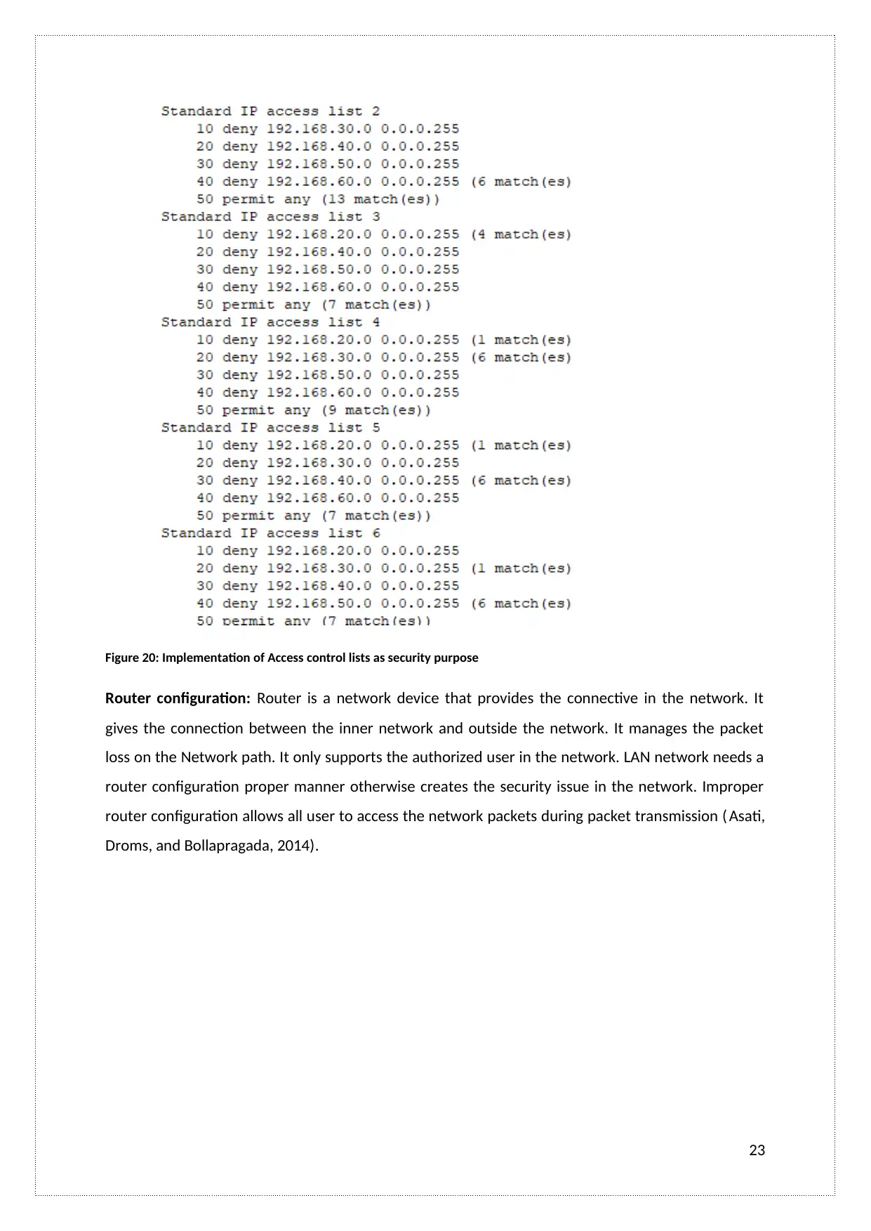
Figure 20: Implementation of Access control lists as security purpose
Router configuration: Router is a network device that provides the connective in the network. It
gives the connection between the inner network and outside the network. It manages the packet
loss on the Network path. It only supports the authorized user in the network. LAN network needs a
router configuration proper manner otherwise creates the security issue in the network. Improper
router configuration allows all user to access the network packets during packet transmission ( Asati,
Droms, and Bollapragada, 2014).
23
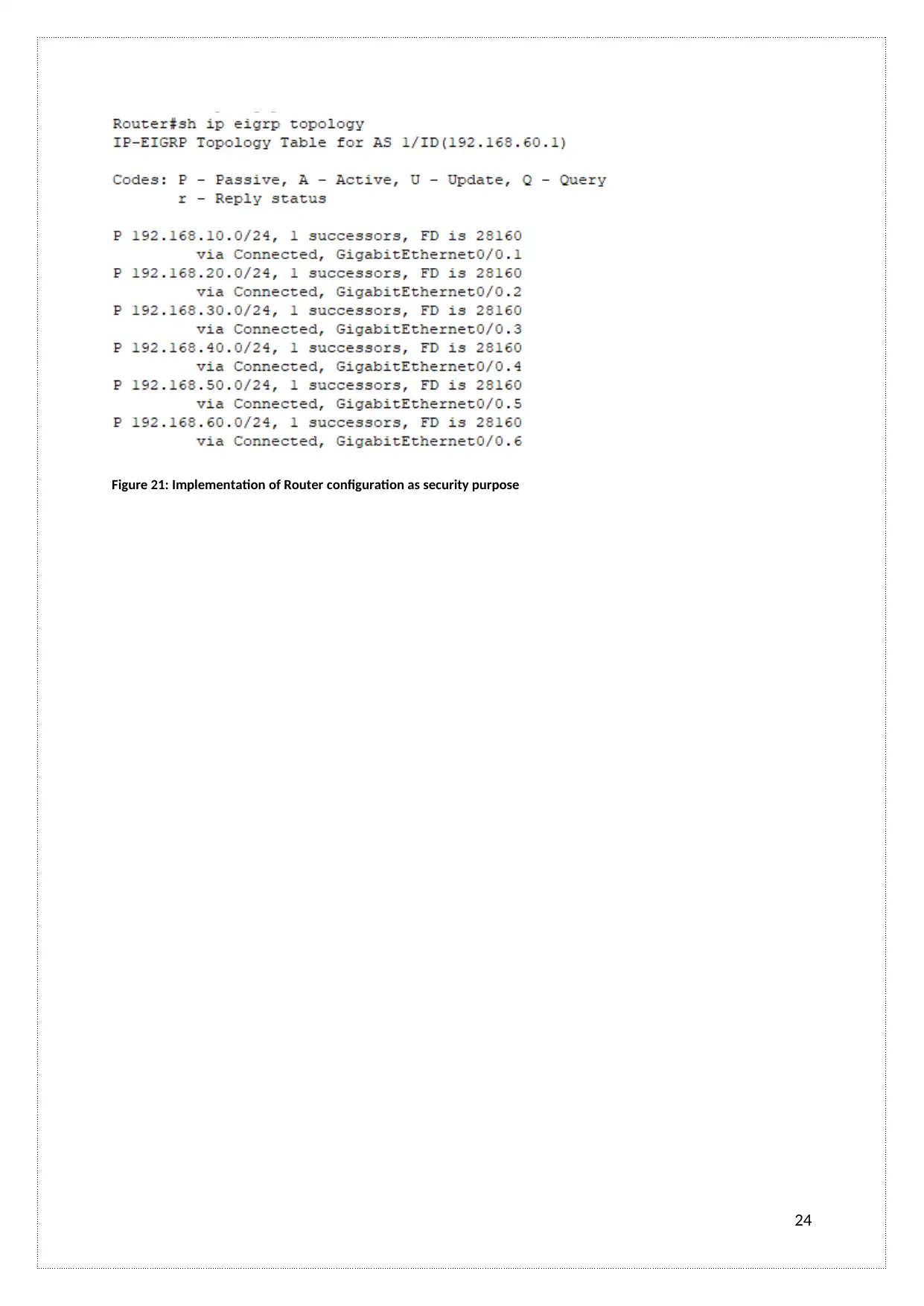
Figure 21: Implementation of Router configuration as security purpose
24
24
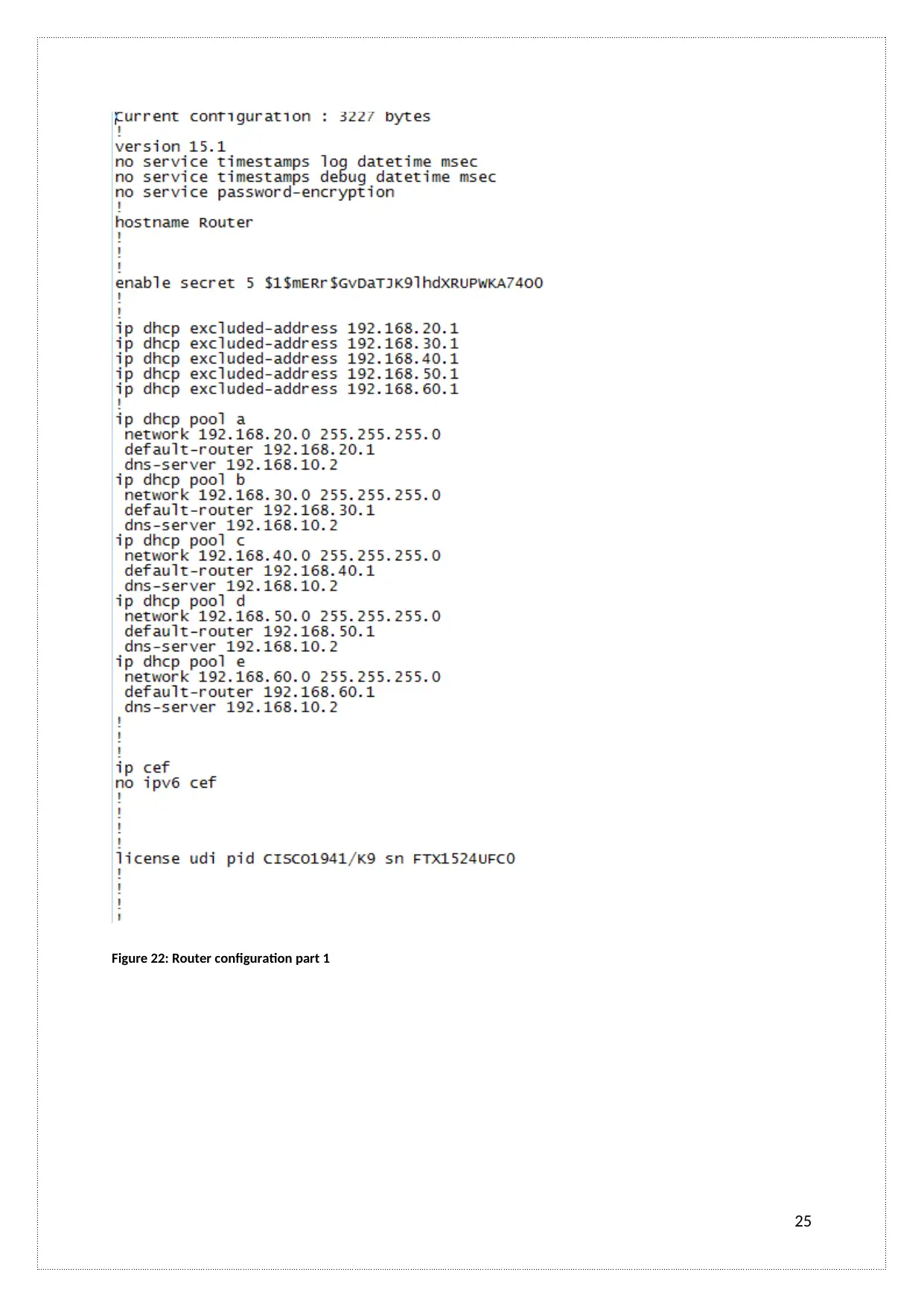
Figure 22: Router configuration part 1
25
25
Paraphrase This Document
Need a fresh take? Get an instant paraphrase of this document with our AI Paraphraser
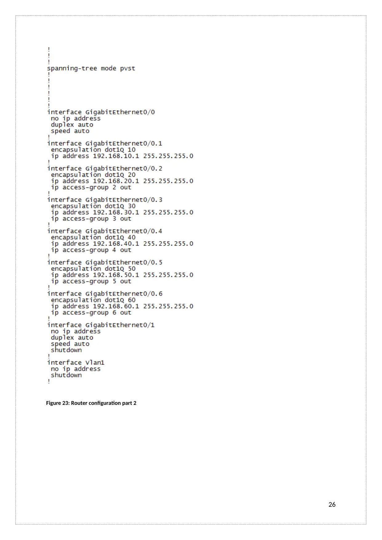
Figure 23: Router configuration part 2
26
26
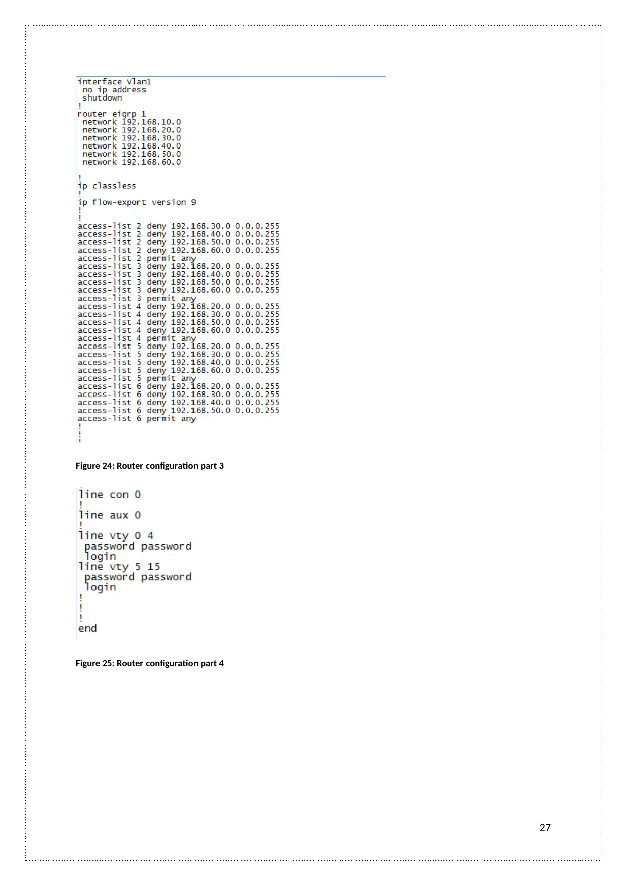
Figure 24: Router configuration part 3
Figure 25: Router configuration part 4
27
Figure 25: Router configuration part 4
27
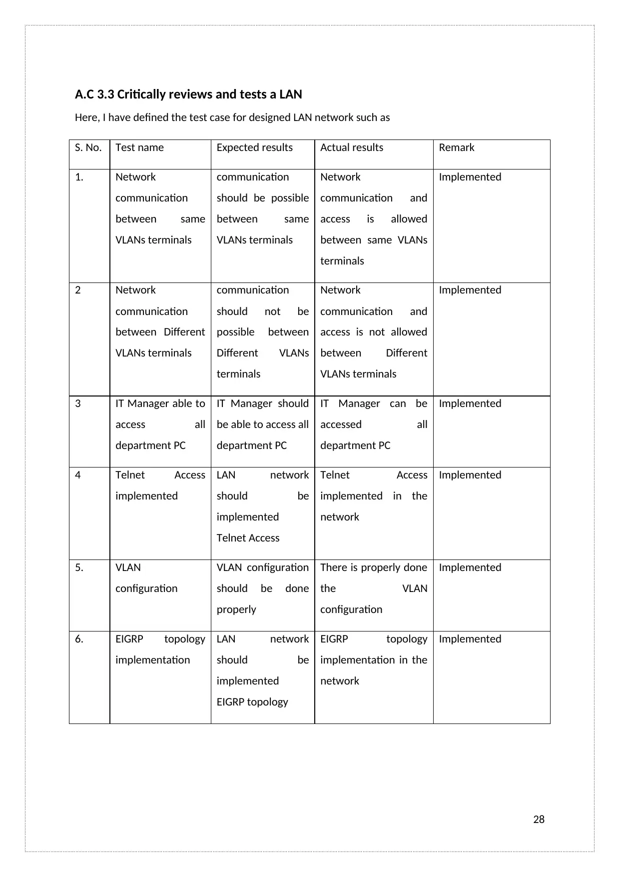
A.C 3.3 Critically reviews and tests a LAN
Here, I have defined the test case for designed LAN network such as
S. No. Test name Expected results Actual results Remark
1. Network
communication
between same
VLANs terminals
communication
should be possible
between same
VLANs terminals
Network
communication and
access is allowed
between same VLANs
terminals
Implemented
2 Network
communication
between Different
VLANs terminals
communication
should not be
possible between
Different VLANs
terminals
Network
communication and
access is not allowed
between Different
VLANs terminals
Implemented
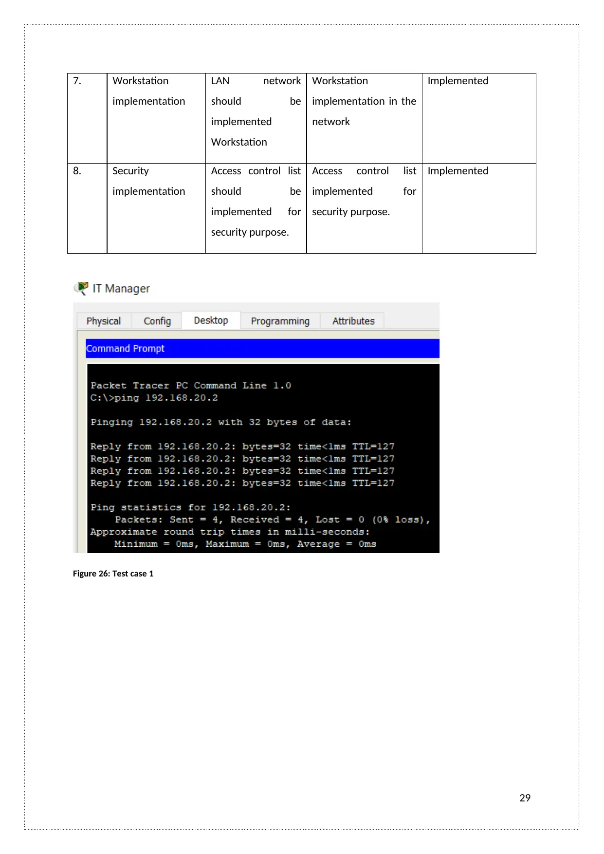
3 IT Manager able to
access all
department PC
IT Manager should
be able to access all
department PC
IT Manager can be
accessed all
department PC
Implemented
4 Telnet Access
implemented
LAN network
should be
implemented
Telnet Access
Telnet Access
implemented in the
network
Implemented
5. VLAN
configuration
VLAN configuration
should be done
properly
There is properly done
the VLAN
configuration
Implemented
6. EIGRP topology
implementation
LAN network
should be
implemented
EIGRP topology
EIGRP topology
implementation in the
network
Implemented
28
Here, I have defined the test case for designed LAN network such as
S. No. Test name Expected results Actual results Remark
1. Network
communication
between same
VLANs terminals
communication
should be possible
between same
VLANs terminals
Network
communication and
access is allowed
between same VLANs
terminals
Implemented
2 Network
communication
between Different
VLANs terminals
communication
should not be
possible between
Different VLANs
terminals
Network
communication and
access is not allowed
between Different
VLANs terminals
Implemented
3 IT Manager able to
access all
department PC
IT Manager should
be able to access all
department PC
IT Manager can be
accessed all
department PC
Implemented
4 Telnet Access
implemented
LAN network
should be
implemented
Telnet Access
Telnet Access
implemented in the
network
Implemented
5. VLAN
configuration
VLAN configuration
should be done
properly
There is properly done
the VLAN
configuration
Implemented
6. EIGRP topology
implementation
LAN network
should be
implemented
EIGRP topology
EIGRP topology
implementation in the
network
Implemented
28
Secure Best Marks with AI Grader
Need help grading? Try our AI Grader for instant feedback on your assignments.
7. Workstation
implementation
LAN network
should be
implemented
Workstation
Workstation
implementation in the
network
Implemented
8. Security
implementation
Access control list
should be
implemented for
security purpose.
Access control list
implemented for
security purpose.
Implemented
Figure 26: Test case 1
29
implementation
LAN network
should be
implemented
Workstation
Workstation
implementation in the
network
Implemented
8. Security
implementation
Access control list
should be
implemented for
security purpose.
Access control list
implemented for
security purpose.
Implemented
Figure 26: Test case 1
29
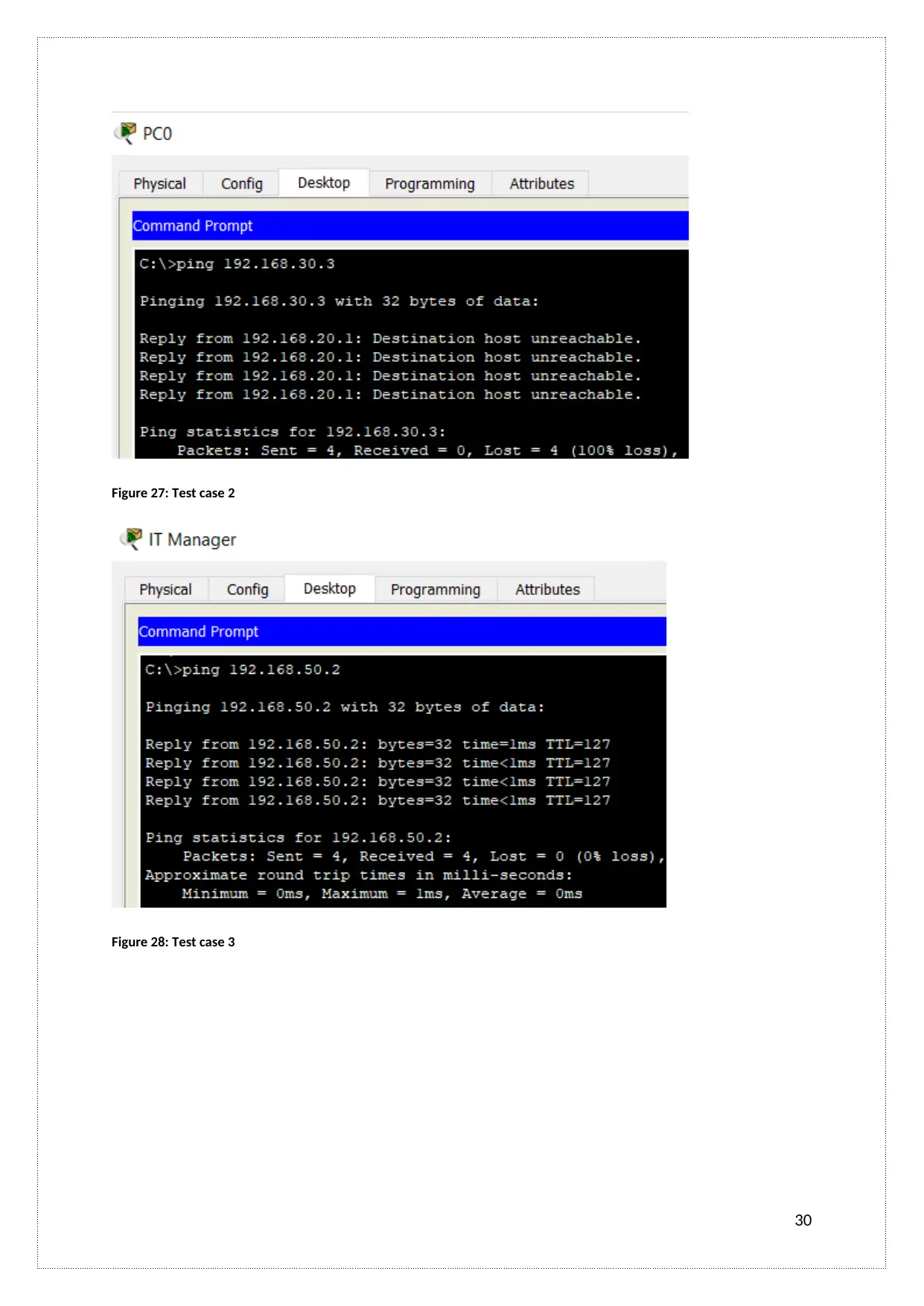
Figure 27: Test case 2
Figure 28: Test case 3
30
Figure 28: Test case 3
30
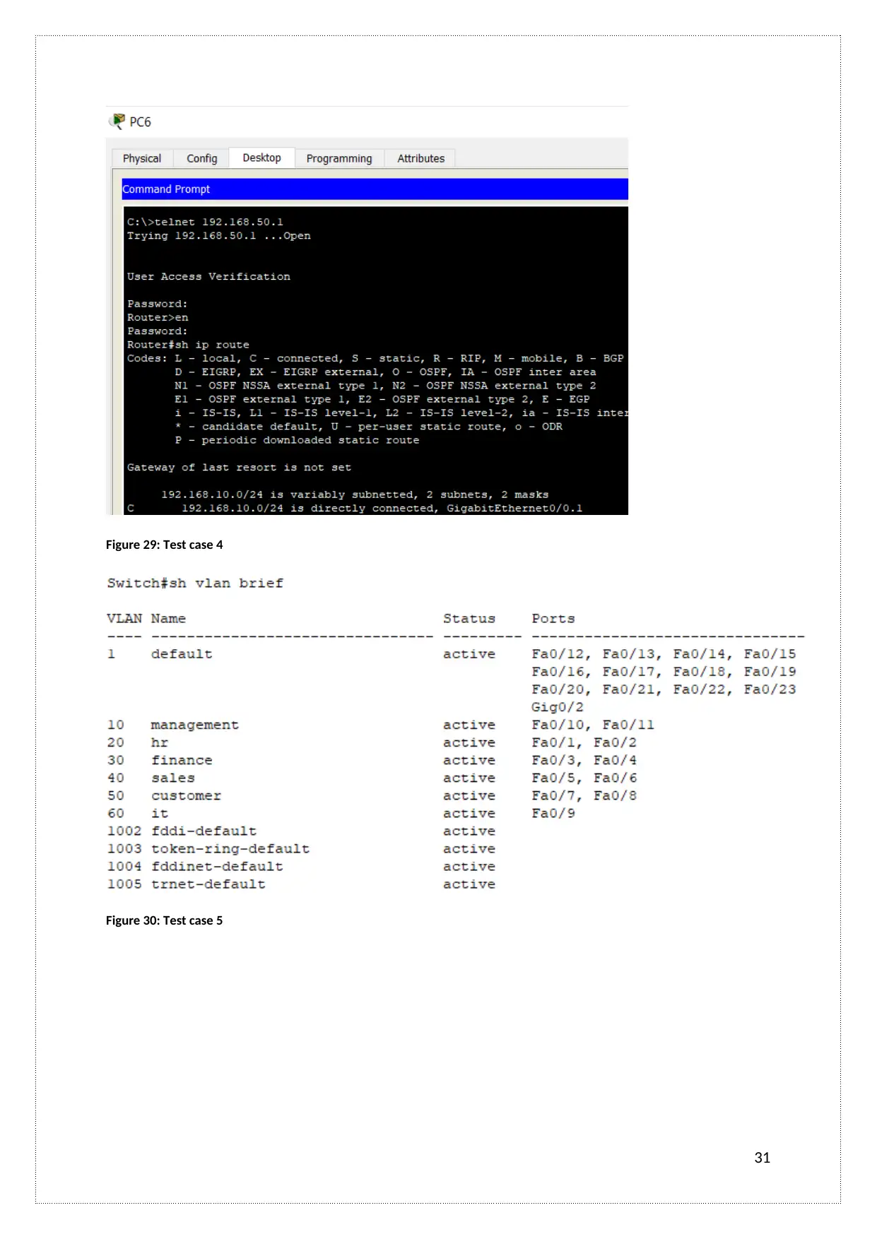
Figure 29: Test case 4
Figure 30: Test case 5
31
Figure 30: Test case 5
31
Paraphrase This Document
Need a fresh take? Get an instant paraphrase of this document with our AI Paraphraser
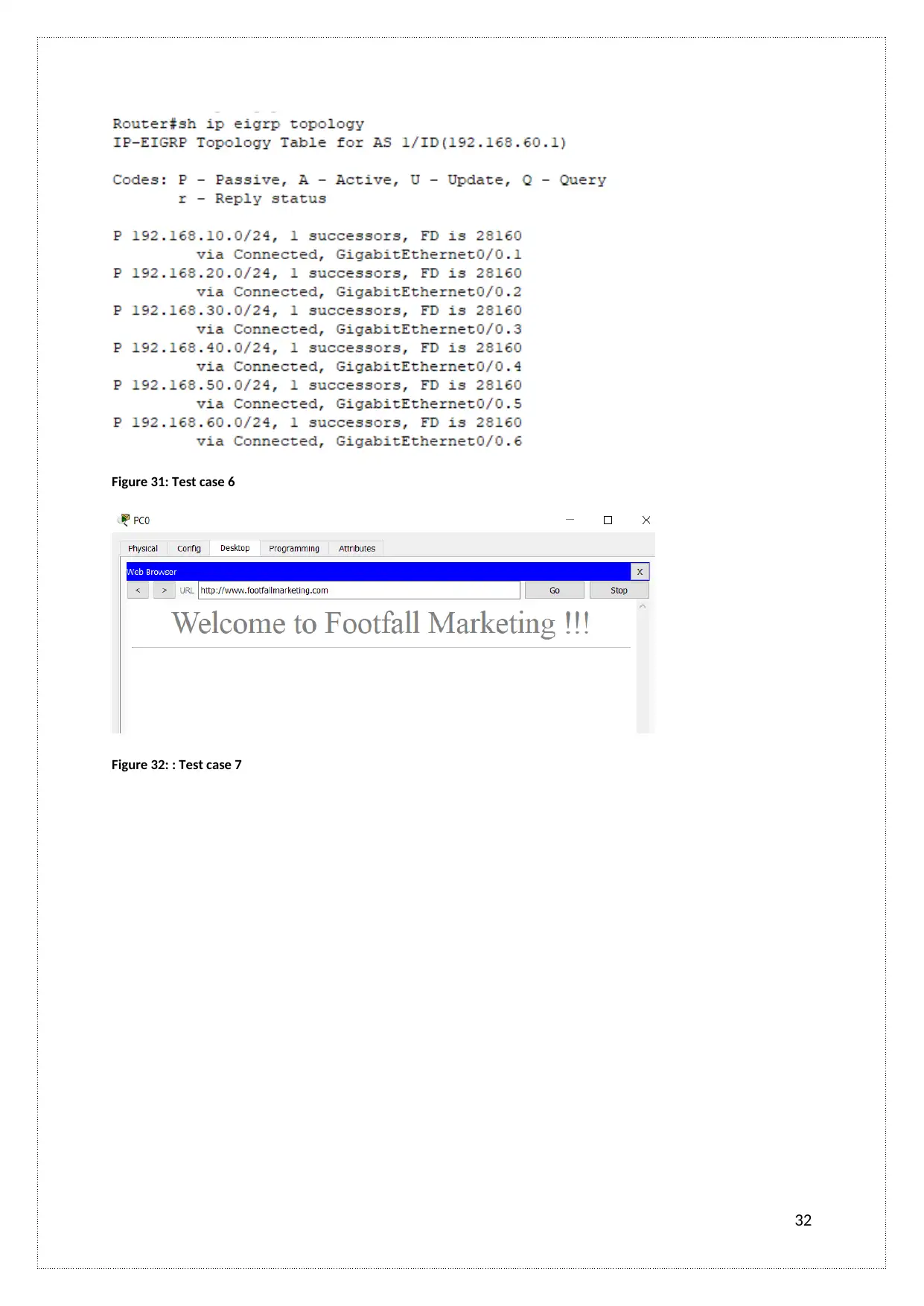
Figure 31: Test case 6
Figure 32: : Test case 7
32
Figure 32: : Test case 7
32

Figure 33: Test case 8
33
33
LO4. Be able to manage LAN infrastructures
A.C 4.1 Critically discusses how this LAN infrastructure will be monitored and
managed (via troubleshooting) if there is an issue during the post-implementation
period.
Here, I have defined monitoring and troubleshooting process for LAN network such as
Monitoring software:
Wireshark: It is an open source and freely available packet analyzer that is used for
communications and software protocol development, network troubleshooting, education,
and analysis. It is terminal-based software that is used by LAN network to Monitoring
network.
Elasticsearch: It is a RESTful, open-source, analytics engine and distributed search assembled
on Apache Lucene. It is a visualization tool for the monitoring process. Fast processing, Easy-
to-use APIs, Plug-ins and Complimentary Tooling, working on the Real-time Index Updates,
and easy to develop any language are the major feature of the Elasticsearch
Microsoft Windows network tools: It is criticized packet analyzers that are enabled for
analyzing, viewing, capturing, net data and decoding network protocols. It is mainly used for
troubleshooting process and network application.
Datadog: It is a monitoring service for the cloud-scale applications. It works on the SaaS-
based data analytics platform. It performed the monitoring process for services, tools,
databases, and servers,
Troubleshooting Commands:
Here, I have defined the various types of Troubleshooting Commands that are used in the LAN
network such as
Ipconfig: It is a Troubleshooting Commands that are used for IP address configuration. It
affects the network connection (Yan, Yu, Gong, and Li, 2016).
Paring: It is a Troubleshooting Commands that are used for network connection and their
profits in between pint and Tracert.
34
Secure Best Marks with AI Grader
Need help grading? Try our AI Grader for instant feedback on your assignments.
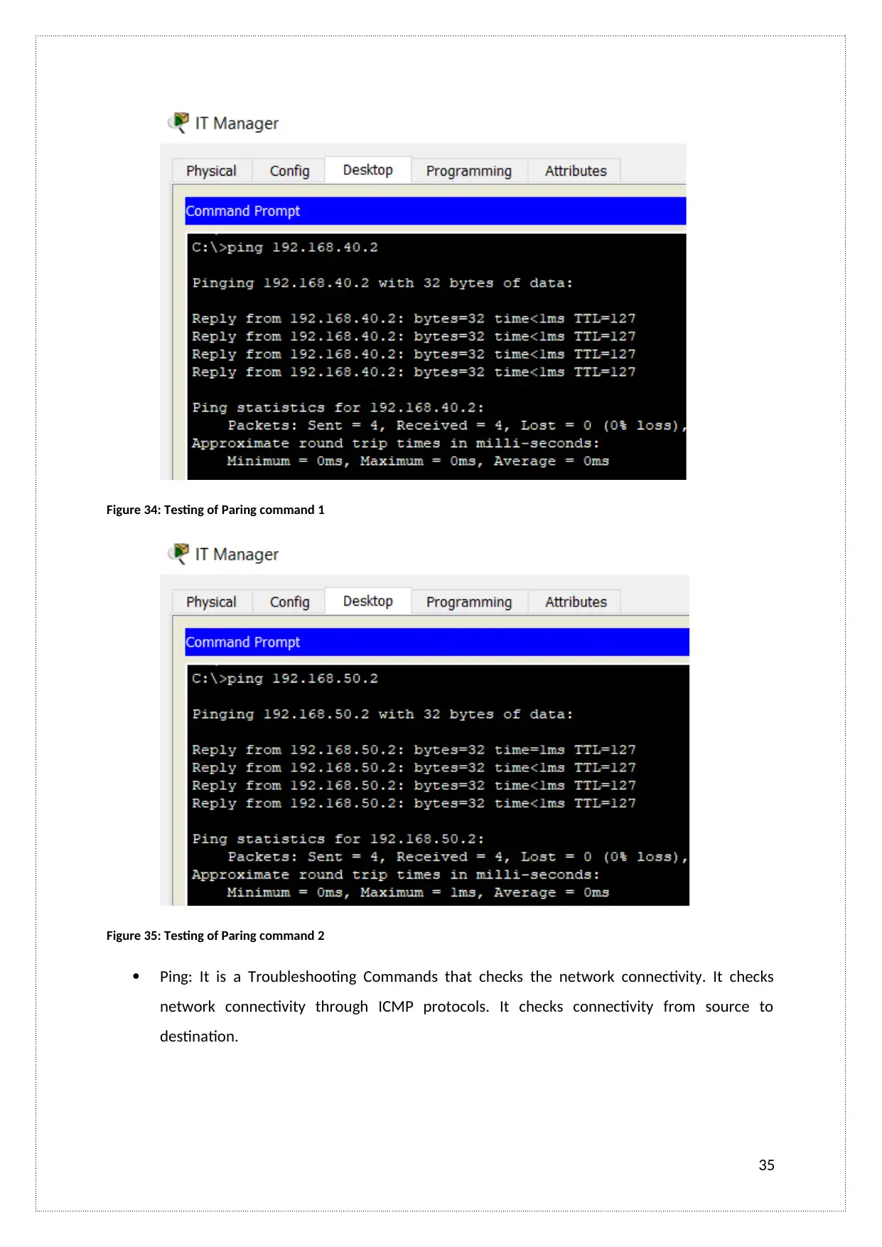
Figure 34: Testing of Paring command 1
Figure 35: Testing of Paring command 2
Ping: It is a Troubleshooting Commands that checks the network connectivity. It checks
network connectivity through ICMP protocols. It checks connectivity from source to
destination.
35
Figure 35: Testing of Paring command 2
Ping: It is a Troubleshooting Commands that checks the network connectivity. It checks
network connectivity through ICMP protocols. It checks connectivity from source to
destination.
35
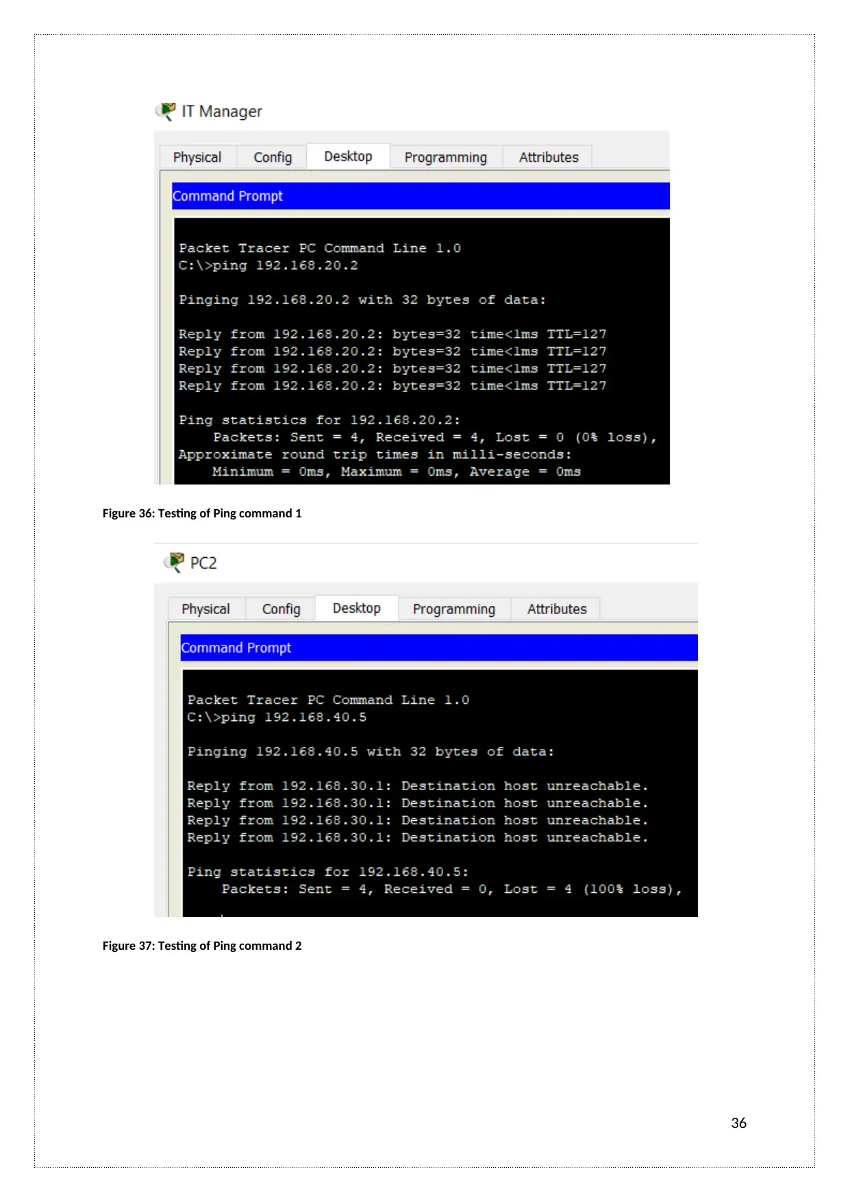
Figure 36: Testing of Ping command 1
Figure 37: Testing of Ping command 2
36
Figure 37: Testing of Ping command 2
36
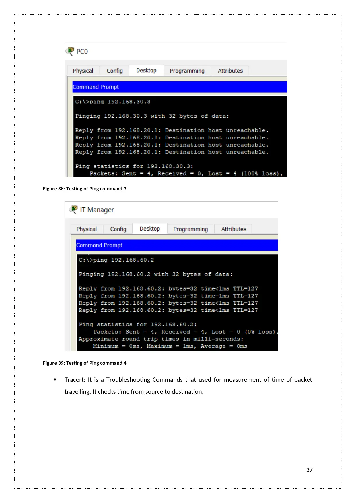
Figure 38: Testing of Ping command 3
Figure 39: Testing of Ping command 4
Tracert: It is a Troubleshooting Commands that used for measurement of time of packet
travelling. It checks time from source to destination.
37
Figure 39: Testing of Ping command 4
Tracert: It is a Troubleshooting Commands that used for measurement of time of packet
travelling. It checks time from source to destination.
37
Paraphrase This Document
Need a fresh take? Get an instant paraphrase of this document with our AI Paraphraser
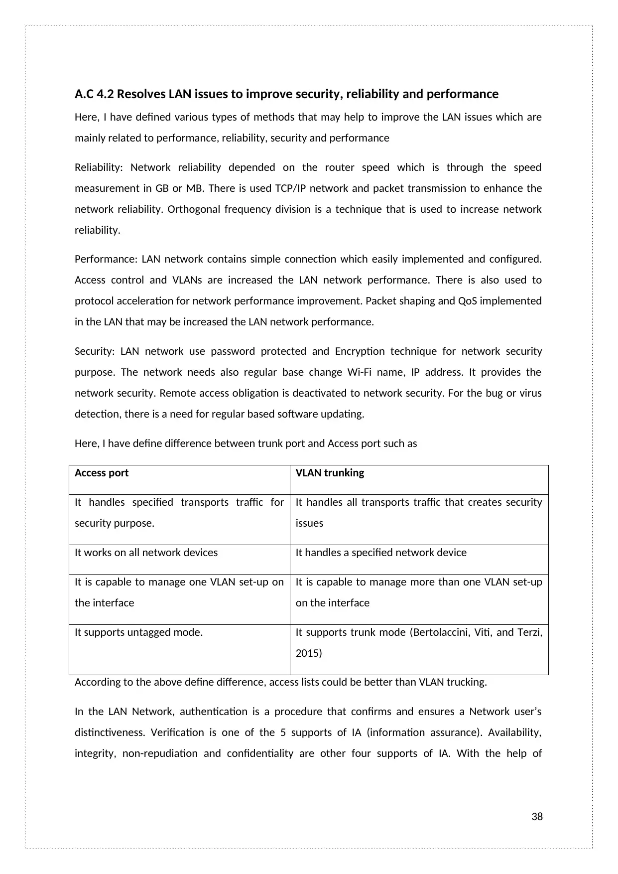
A.C 4.2 Resolves LAN issues to improve security, reliability and performance
Here, I have defined various types of methods that may help to improve the LAN issues which are
mainly related to performance, reliability, security and performance
Reliability: Network reliability depended on the router speed which is through the speed
measurement in GB or MB. There is used TCP/IP network and packet transmission to enhance the
network reliability. Orthogonal frequency division is a technique that is used to increase network
reliability.
Performance: LAN network contains simple connection which easily implemented and configured.
Access control and VLANs are increased the LAN network performance. There is also used to
protocol acceleration for network performance improvement. Packet shaping and QoS implemented
in the LAN that may be increased the LAN network performance.
Security: LAN network use password protected and Encryption technique for network security
purpose. The network needs also regular base change Wi-Fi name, IP address. It provides the
network security. Remote access obligation is deactivated to network security. For the bug or virus
detection, there is a need for regular based software updating.
Here, I have define difference between trunk port and Access port such as
Access port VLAN trunking
It handles specified transports traffic for
security purpose.
It handles all transports traffic that creates security
issues
It works on all network devices It handles a specified network device
It is capable to manage one VLAN set-up on
the interface
It is capable to manage more than one VLAN set-up
on the interface
It supports untagged mode. It supports trunk mode (Bertolaccini, Viti, and Terzi,
2015)
According to the above define difference, access lists could be better than VLAN trucking.
In the LAN Network, authentication is a procedure that confirms and ensures a Network user’s
distinctiveness. Verification is one of the 5 supports of IA (information assurance). Availability,
integrity, non-repudiation and confidentiality are other four supports of IA. With the help of
38
password, smart card, biometric, or fingerprint method, user authentication could better manage
into LAN network
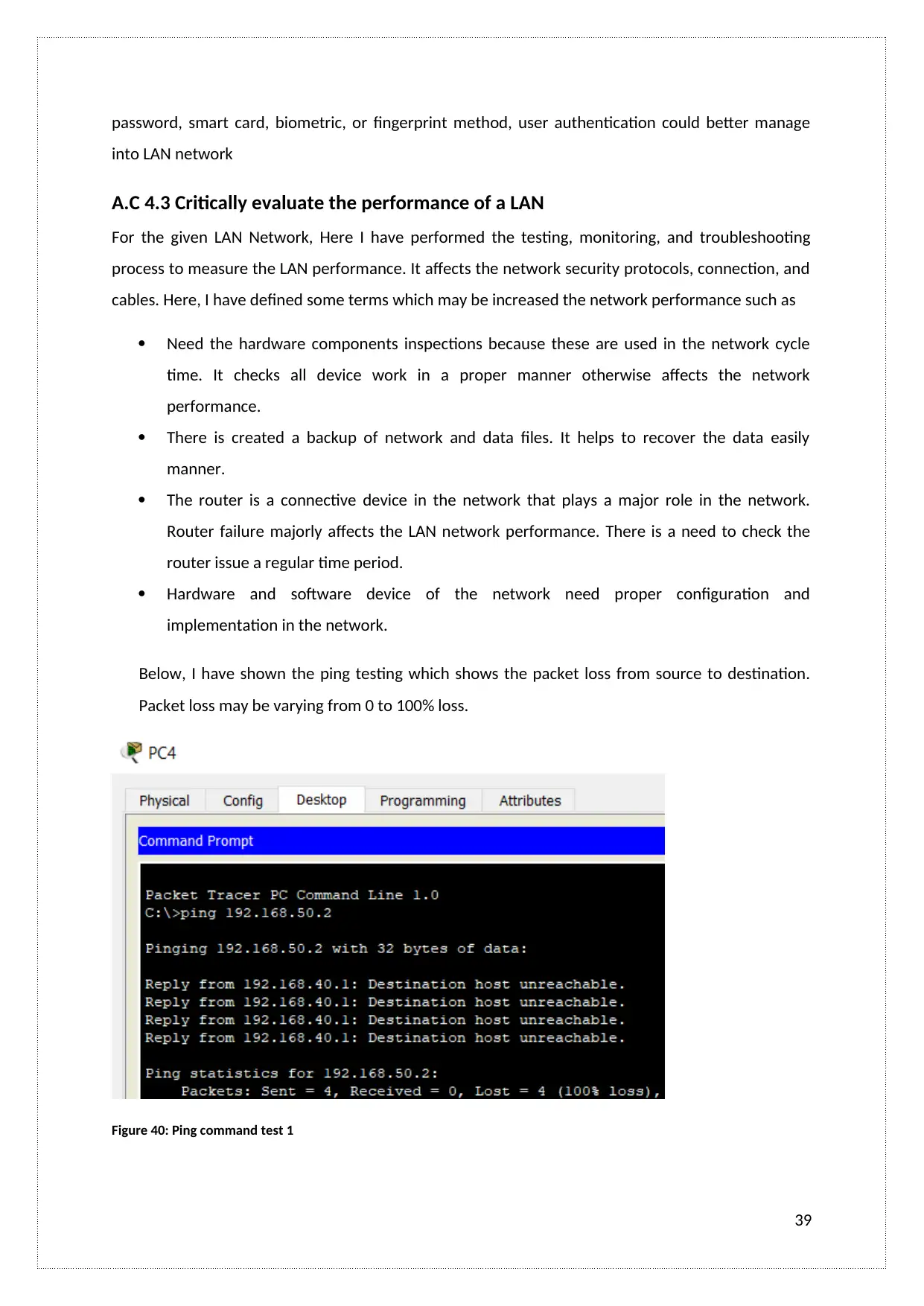
A.C 4.3 Critically evaluate the performance of a LAN
For the given LAN Network, Here I have performed the testing, monitoring, and troubleshooting
process to measure the LAN performance. It affects the network security protocols, connection, and
cables. Here, I have defined some terms which may be increased the network performance such as
Need the hardware components inspections because these are used in the network cycle
time. It checks all device work in a proper manner otherwise affects the network
performance.
There is created a backup of network and data files. It helps to recover the data easily
manner.
The router is a connective device in the network that plays a major role in the network.
Router failure majorly affects the LAN network performance. There is a need to check the
router issue a regular time period.
Hardware and software device of the network need proper configuration and
implementation in the network.
Below, I have shown the ping testing which shows the packet loss from source to destination.
Packet loss may be varying from 0 to 100% loss.
Figure 40: Ping command test 1
39
into LAN network
A.C 4.3 Critically evaluate the performance of a LAN
For the given LAN Network, Here I have performed the testing, monitoring, and troubleshooting
process to measure the LAN performance. It affects the network security protocols, connection, and
cables. Here, I have defined some terms which may be increased the network performance such as
Need the hardware components inspections because these are used in the network cycle
time. It checks all device work in a proper manner otherwise affects the network
performance.
There is created a backup of network and data files. It helps to recover the data easily
manner.
The router is a connective device in the network that plays a major role in the network.
Router failure majorly affects the LAN network performance. There is a need to check the
router issue a regular time period.
Hardware and software device of the network need proper configuration and
implementation in the network.
Below, I have shown the ping testing which shows the packet loss from source to destination.
Packet loss may be varying from 0 to 100% loss.
Figure 40: Ping command test 1
39
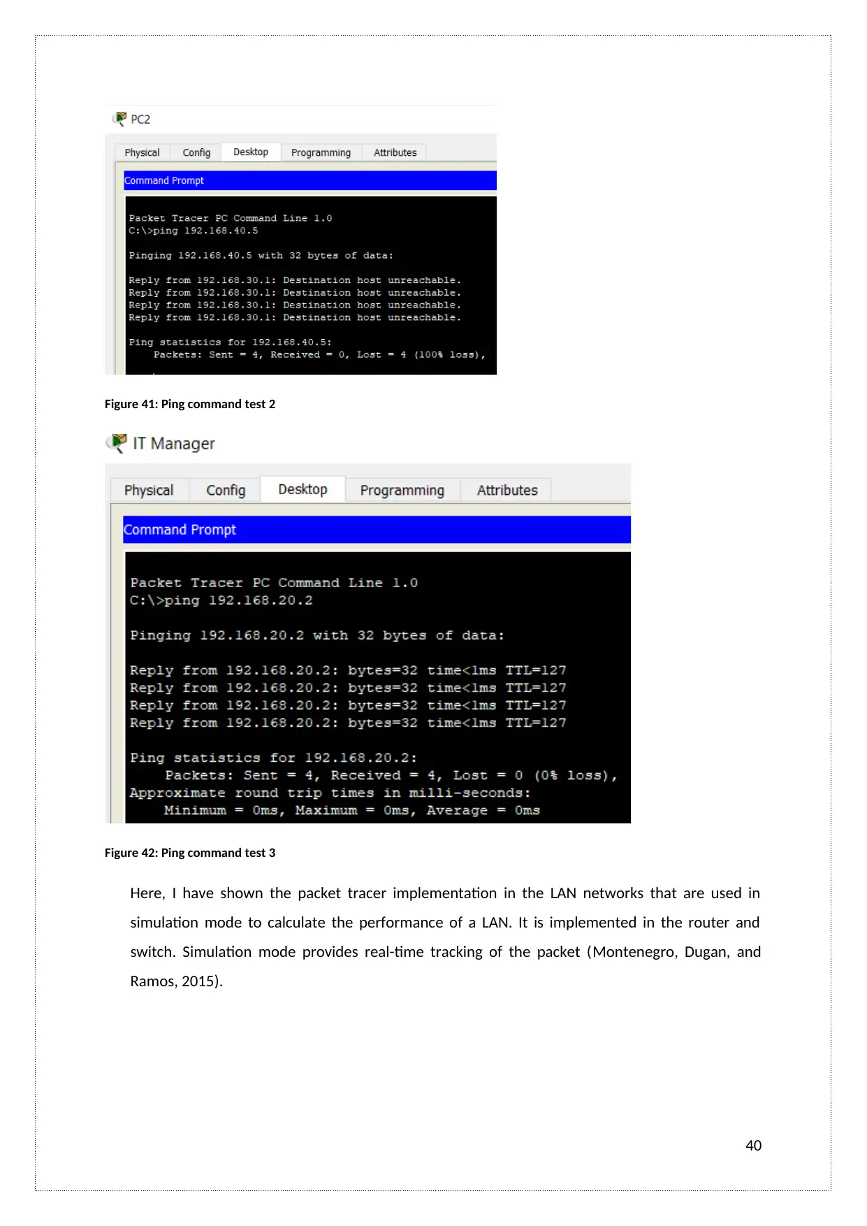
Figure 41: Ping command test 2
Figure 42: Ping command test 3
Here, I have shown the packet tracer implementation in the LAN networks that are used in
simulation mode to calculate the performance of a LAN. It is implemented in the router and
switch. Simulation mode provides real-time tracking of the packet (Montenegro, Dugan, and
Ramos, 2015).
40
Secure Best Marks with AI Grader
Need help grading? Try our AI Grader for instant feedback on your assignments.
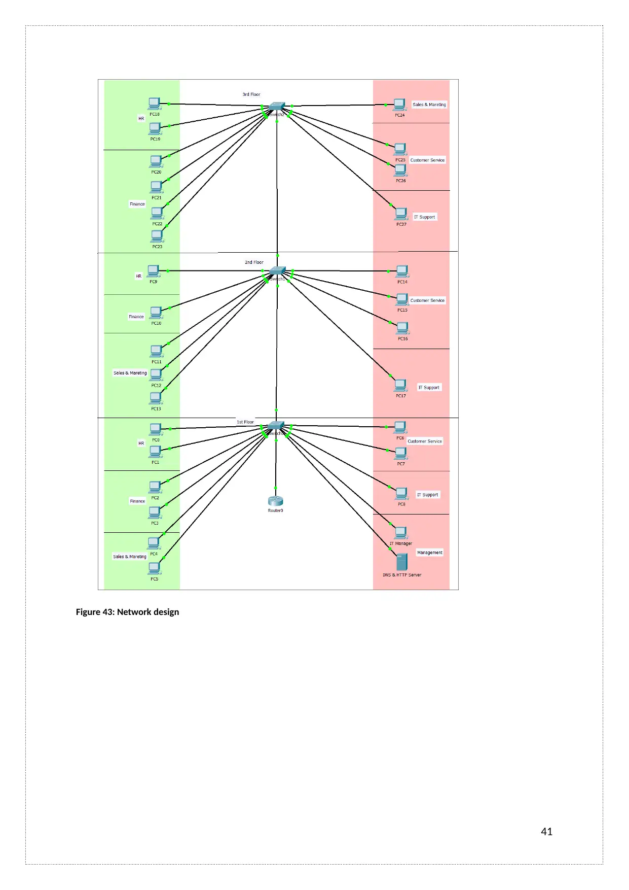
Figure 43: Network design
41
41
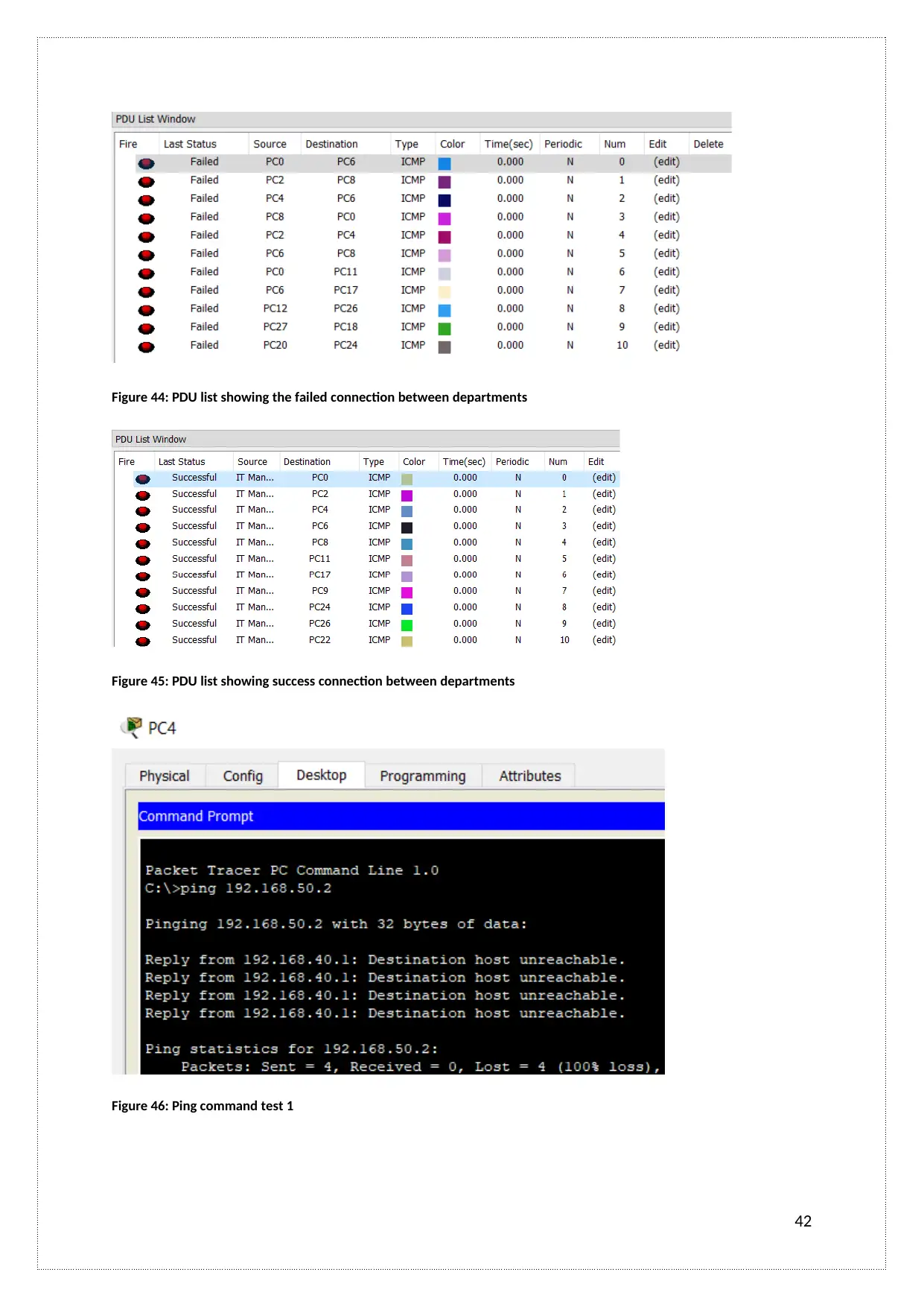
Figure 44: PDU list showing the failed connection between departments
Figure 45: PDU list showing success connection between departments
Figure 46: Ping command test 1
42
Figure 45: PDU list showing success connection between departments
Figure 46: Ping command test 1
42

Figure 47: Ping command test 2
Figure 48: Ping command test 3
M3: Here, I have designed the LAN network on the Cisco Packet Tracer software tool with DNS, and
HTPP server, Router configuration, Workstation implementation process. LAN Network is designed
EIGRP topology. Network performance depended on Jitter, Throughput, Bandwidth, Latency, and
Packet Loss. M3 is successfully achieved report part 3.1 and 4.3.
D1: I have achieved the D1 in section 4.3 of the report. Network performance is measured on the
packet tracer with the simulated model.
43
Paraphrase This Document
Need a fresh take? Get an instant paraphrase of this document with our AI Paraphraser

D2: I have achieved the D2 in section 3.1 and 3.2 of the report. Network infrastructure is designed
according to user and system requirements. It designed on packet tracer
D3: D3 is successfully achieved in section 3.3, 3.2, and 3.1. I have designed the Network
infrastructure with a creative idea. There is also performed the testing process to check fulfilled user
requirement.
44
according to user and system requirements. It designed on packet tracer
D3: D3 is successfully achieved in section 3.3, 3.2, and 3.1. I have designed the Network
infrastructure with a creative idea. There is also performed the testing process to check fulfilled user
requirement.
44
References:
Asati, R., Droms, R. and Bollapragada, V., Cisco Technology Inc, 2014. Automated network
device provisioning using dynamic host configuration protocol. U.S. Patent 8,918,531.
Berlovitch, A., Shurman, M. and Shoua, M., Lucent Technologies Networks Ltd,
2000. Apparatus and method for assigning virtual LANs to a switched network. U.S. Patent
6,061,334.
Bertolaccini, L., Viti, A. and Terzi, A., 2015. Ergon-trial: ergonomic evaluation of single-port
access versus three-port access video-assisted thoracic surgery. Surgical endoscopy, 29(10),
pp.2934-2940.
Bull, R., Matthews, J.N. and Trumbull, K.A., 2016. VLAN hopping, ARP poisoning and man-in-
the-middle attacks in virtualized environments.
Davis, D. (2018). The three main Network Topologies and how they can work for you. [online]
David’s Cisco Networking Blog. Available at:
https://itknowledgeexchange.techtarget.com/cisco/the-three-main-network-topologies-
and-how-they-can-work-for-you/ [Accessed 27 Jul. 2018].
Montenegro, D., Dugan, R. and Ramos, G., 2015, June. Harmonics analysis using sequential-
time simulation for addressing smart grid challenges. In Int. Conf. Electricity Distribution,
Lyon, France (pp. 15-18).
Sivakumar, S.C., Robertson, W., Artimy, M. and Aslam, N., 2005. A web-based remote
interactive laboratory for Internetworking education. IEEE Transactions on Education, 48(4),
pp.586-598.
Stallings, W. (2018). Internet Traffic Quality of Service | Quality of Service (QoS) for Local
Area Networks (LANs) | InformIT. [online] Informit.com. Available at:
http://www.informit.com/articles/article.aspx?p=25315&seqNum=5 [Accessed 27 Jul. 2018].
Yan, Q., Yu, F.R., Gong, Q. and Li, J., 2016. Software-defined networking (SDN) and
distributed denial of service (DDoS) attacks in cloud computing environments: A survey,
some research issues, and challenges. IEEE Communications Surveys & Tutorials, 18(1),
pp.602-622.
45
1 out of 45
Related Documents


Your All-in-One AI-Powered Toolkit for Academic Success.
+13062052269
info@desklib.com
Available 24*7 on WhatsApp / Email
![[object Object]](/_next/static/media/star-bottom.7253800d.svg)
Unlock your academic potential
© 2024 | Zucol Services PVT LTD | All rights reserved.