Competency Demonstration Report: Laser Image Transmission Project
VerifiedAdded on 2020/03/16
|9
|1635
|126
Report
AI Summary
This report details a student's competency demonstration project on image transmission using laser communication. The project, conducted at Jawaharlal Nehru Technological University, focused on developing a one-way laser communication system capable of transmitting text and images wirelessly. The student's role involved developing the electronic components, specifically the transmitter and receiver modules, and participating in the testing phase. The report outlines the project's objectives, including eliminating cables and increasing data transmission bandwidth. It explains the application of free space optics technology, the engineering knowledge applied, and the challenges faced, such as obtaining research materials and programming issues, along with the solutions implemented. The project's innovative aspects, collaborative work, and successful completion are also highlighted, emphasizing the use of lasers for secure and high-bandwidth image transmission.

COMPETENCY
DEMONSTRATION REPORT
Career Episode 1
MOHD RAHMATH ULLAH HUSSAIN
DEMONSTRATION REPORT
Career Episode 1
MOHD RAHMATH ULLAH HUSSAIN
Paraphrase This Document
Need a fresh take? Get an instant paraphrase of this document with our AI Paraphraser
CE 1.1 Project Information
Name of the project: Image transmission using laser communication
Location of the project: Andhra Pradesh
Project Duration: 2007 - 2008
Organization: Jawaharlal Nehru Technological University, Kukatpally
Role and Designation during the time: Team member
CE 1.2 Project Background
CE 1.2.1 Characteristics of the project
The project that I had developed was based on a one way laser communication system
which is capable of the transmission of both type of data, text and images, the methods of laser
communication is a mode of wireless connection. They have a similar working mechanism as the
fibre optic with the exception that the signals are transmitted through wireless mechanism
instead of electrical lines. Though the transmission signals requires a line of sight for the
communication process but there is an elimination of buried cables and broadcast rights. The
system can send arbitrary data at 27.7 kbps baud. The encoded image given to MC, the MCU
passes the signal to the UART. The UART sets a transmit pin high or low according to the serial
protocol.
CE 1.2.2 Objectives developed for the project
For the development of the project I had set out the following set of objectives which
were to be followed for the best quality delivery of the project:
To remove the use of any cables and wires for the transmission of images and data.
To make a device which will help in the easiest mode of communication with the help
of lasers.
To combat the ever increasing need for higher bandwidth of data transmission.
CE 1.2.3 My area of work
I was responsible for the development of the electronic component of the project device.
The electronic component mainly consisted of the transmitter and the receiver module of the
project. Each of the transmitter and the receiver were the same. The only difference between
them were the inclusion of a laser transmitter circuit and a laser receiver circuit. I had also helped
in the testing of the device. The testing results were collected and then shared with the final
documentation of the project module.
⊘ This is a preview!⊘
Do you want full access?
Subscribe today to unlock all pages.

Trusted by 1+ million students worldwide
CE 1.2.4 Project Group
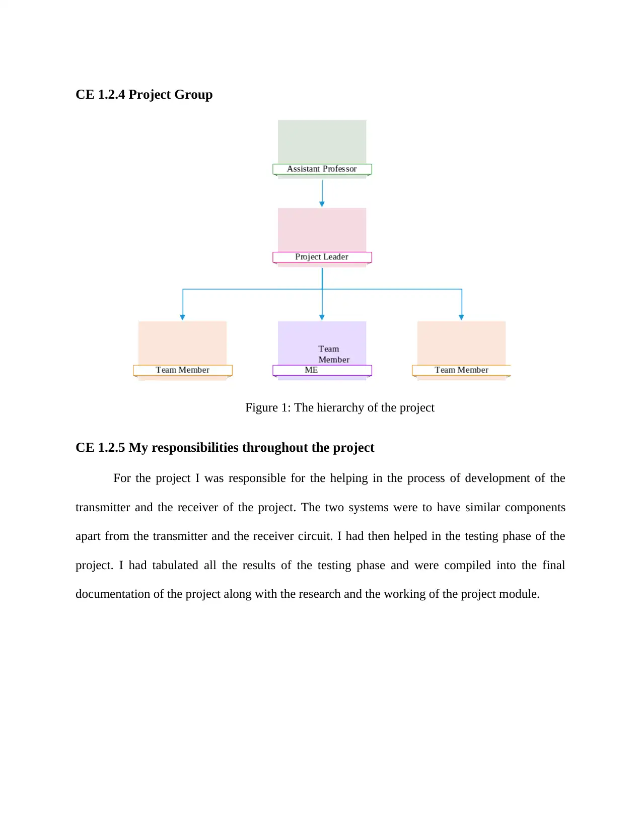
Figure 1: The hierarchy of the project
CE 1.2.5 My responsibilities throughout the project
For the project I was responsible for the helping in the process of development of the
transmitter and the receiver of the project. The two systems were to have similar components
apart from the transmitter and the receiver circuit. I had then helped in the testing phase of the
project. I had tabulated all the results of the testing phase and were compiled into the final
documentation of the project along with the research and the working of the project module.
Paraphrase This Document
Need a fresh take? Get an instant paraphrase of this document with our AI Paraphraser
CE 1.3 Distinctive Activity
CE 1.3.1 Comprehending the theory of the project
The basic theory which was used for the project was the free space optics technology
which makes use the propagation of light for the transmission of data between a pair of points or
devices. In this technology there is a transmission of visible or infrared light which has been pre-
modulated with the data for the transmission. I had taken up this theoretical approach for the
project so as to make the use of laser technology and to reduce the use of guided cables for the
transmission of data between two points. Laser has been used in this system as the laser has the
minimal type of data loss in the case of transmission of data and can be transmitted over a longer
distance without the issue of incorporation of any kind of noise or loss of data.
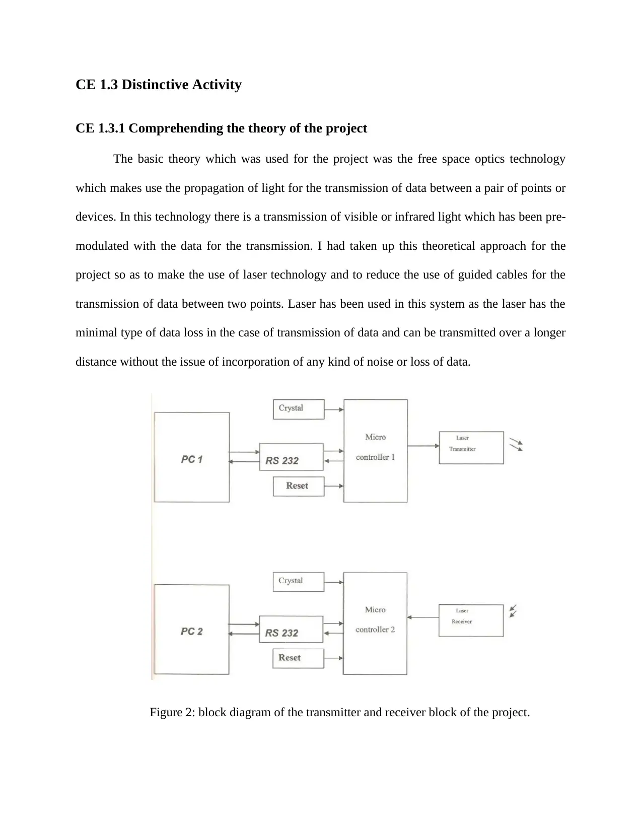
Figure 2: block diagram of the transmitter and receiver block of the project.
CE 1.3.2 Engineering knowledge and skills applied in the project
For the development of the project I had applied my knowledge of electronics and
instrumentation engineering. The theories which I had learnt during my course of study was
applied in this project making it possible to understand the working of laser better. I had also
received help from my team members who had conducted the basis research study of the project.
I had then taken the working on the hardware model of the device.
CE 1.3.3 Accomplishment and task performed
The project comprises of 6 modules: personal computer data transmission,
microcontroller, laser light emission, photo receiver module, microcontroller, personal computer
data reception.
Unlike light emitting diodes (LEDs), laser diodes require much greater care in their drive
electronics or else they will die - instantly. There is a maximum current, which must not be
exceeded for even a microsecond - and this depends on the particular device as well as junction
temperature. This sensitivity to overcurrent is due to the very large amount of positive feedback,
which is present when the laser diode is lasing. For encoding RS-232 signals into optical
impulses IrDA SIR Modulation is used because it is mostly closely related to RS-232. The
AT89C51 is allow-power; high-performance CMOS 8-bit microcomputer with 4k bytes of Flash
programmable and erasable read only memory (PEROM). The device is manufactured using
ATMEL’s high-density nonvolatile memory technology and is compatible with the industry-
standard MCS-51 instruction set and in out. Software Languages used to write the code for a
Microcontroller are: Assembly Embedded C and Dynamic C. Laser diode is a laser where the
active medium is a laser diode similar to that found in a light-emitting diode. The laser diode
most common and practical type is formed from a p-n junction and powered by injected
⊘ This is a preview!⊘
Do you want full access?
Subscribe today to unlock all pages.

Trusted by 1+ million students worldwide
electrical current. With the help of laser I could transmit data and images, first the selected image
file is converted into bits or binary format these bits are given to the max-232 for voltage
conversion. Max-232 will converts the voltage from 12 to 5 volts after that it is given to the
microcontroller. In microcontroller the signal is coded by using keil software and given to the
laser, with the help of laser modulation or photons it is given to the photo transistor and the same
process is repeated.
CE 1.3.4 Identified issues and their solutions
1.3.4.1 Issues
The major issue which I had faced was to get hold of the correct research materials to
make the project a research based work. The next problem which I had faced was the issue of not
able to transmit the image with the laser beam.
1.3.4.2 Solutions
I then consulted with my project supervisor who had helped us in collecting some of the
best research materials for our project. The study was done and the best project was delivered in
terms of quality. The laser was not able to receive the information about what needed to be
transmitted. The programming had not been done correctly. When the programming was checked
again it was found that the pixels were not set to any colour. Even though the pixels were being
transmitted the printing was not being done due to the colour unavailability.
CE 1.3.5 Plan to produce creative and innovative work
The project itself can be said to be of an innovative work. The project makes use of laser
based image transmission. The amount of data loss is of minimum quantity. The advantages for
the use of laser are many; high amount security in transmission medium, high amount of bit rate,
Paraphrase This Document
Need a fresh take? Get an instant paraphrase of this document with our AI Paraphraser
has full duplex transmission capability and can travel with minimum amount of dispersion of the
ray. With the visibility of the laser being used in the project it can also be used to maintain thee
aiming process to the receiver.
CE 1.3.6 Collaborative work
For the project I had collaborated with my team members and my project supervisor. My
team mates had conducted the research on the project topic. Based on the research conducted I
had taken the initiative to develop the hardware module of the project consisting of the
transmitter and the receiver module of the project. I had also initiated most of the team meetings
where I had discussed about the progress of the project and the issues which I were facing in the
project implementation.
CE 1.4 Project Review
CE 1.4.1 Project Overview
After the testing of the project I was able to conclude that the project was completed
successfully. The project was able to transmit image with the help of laser. The project had
followed the timeline which had been set forward for the project. I had also helped my team as a
positive figure which helped us to complete the project with ease and were also able to meet the
objective of the project.
CE 1.4.2 My contribution to work
For the project I had helped my team mated in the development and the designing of the
hardware module of the project according to the basis of the research conducted by my team.
The hardware module consists of the transmitter and the receiver module for the data

communication with the laser system. At the end of the project I had also helped in the testing of
the device and then tabulated the details into a complete documentation.
the device and then tabulated the details into a complete documentation.
⊘ This is a preview!⊘
Do you want full access?
Subscribe today to unlock all pages.

Trusted by 1+ million students worldwide
1 out of 9
Related Documents
Your All-in-One AI-Powered Toolkit for Academic Success.
+13062052269
info@desklib.com
Available 24*7 on WhatsApp / Email
![[object Object]](/_next/static/media/star-bottom.7253800d.svg)
Unlock your academic potential
Copyright © 2020–2026 A2Z Services. All Rights Reserved. Developed and managed by ZUCOL.


