NG3S900 Advanced Embedded Systems Case Study
VerifiedAdded on 2019/09/18
|16
|2836
|659
Case Study
AI Summary
This document outlines a case study assignment for the Advanced Embedded Systems module (NG3S900) at the University of South Wales. The assignment is divided into two parts, focusing on the development of a smart autonomous bot. Part 1 involves designing and implementing a basic prototype, while Part 2 focuses on porting the system to an RTOS (µCosIII). The tasks include background research, hardware and software design, implementation, and testing. The document also includes a detailed marking scheme, learning outcomes, and appendices with technical specifications and links to relevant resources. The goal is to provide students with hands-on experience in embedded systems development.

Mark Awarded: %
UNIVERSITY OF SOUTH WALES- FCES
Assessment Cover Sheet and Feedback Form
2016/17
Module Code: NG3S900 Module Title: Advanced Embedded Systems Lecturer: BM
Assignment No: 1/1 No. of pages in total including this page: 9 Maximum Word Count:
N/A
Assignment Title: Case study: Set of Tasks-
Part-1: Smart Autonomous Bot-
Tasks details: see attached
Date Set: 1st Nov’2016 Submission Date: 28th March 2017 Feedback Date: 20 days from due
Section A: Record of Submission
Record of Submission and Plagiarism Declaration
I declare that this assignment is my own work and that the sources of information and
material I have used (including the internet) have been fully identified and properly
acknowledged as required in the referencing guidelines provided.
Student Number:
You are required to acknowledge that you have read the above statement by writing your student
number(s) above.
(If this is a group assignment, please provide the student numbers of ALL group members)
Details of Submission
Note that all work handed in after the submission date and within 5 working days will be capped at 40%.
No marks will be awarded if the assignment is submitted after the late submission date unless
mitigating circumstances are applied for and accepted.
IT IS YOUR RESPONSIBILITY TO KEEP A RECORD OF ALL WORK SUBMITTED.
An electronic copy of your work should be submitted via Blackboard.
Work should also be submitted to the member of academic staff responsible for setting your work.
Work not submitted to the lecturer responsible may, exceptionally, be submitted (on the
submission date) to the reception of the Faculty of Advanced Technology, which is on the 2nd floor
of G block (Room G221) where a receipt will be issued.
Mitigating Circumstances: if there are any exceptional circumstances which may have affected
your ability to undertake or submit this assignment, make sure you contact the Faculty Advice Shop
on 01443 482540 (G221).
You are required to acknowledge that you have read the above statements by
writing your student number (s) in the box:
Student Number:
Section B : Marking and Assessment
This assignment will be marked out of 100% It is estimated that you should spend
1
Paraphrase This Document
Need a fresh take? Get an instant paraphrase of this document with our AI Paraphraser

This assignment contributes to 30% of the total module marks.
This assignment is bonded / non- bonded. Details :
approximately 24 hours on this
written assignment.
Learning Outcomes- http://icis.southwales.ac.uk
This assignment addresses the following learning outcome(s) of the module:
LO1. The student will be able to apply formal design methodologies in the development of embedded solutions
LO2: The student will be able to critically analyse an embedded system problem and select the appropriate design
methodology to implement a software solution.
For this assignment, the following learning outcomes supplements should also be taken into account:
LO3.Critically evaluate a User Requirement Specification and identify the appropriate design methodology
required to provide solutions meeting the functionality and requirements defined.
LO4.Will be able to design complex embedded solutions using a pre-emptive RTOS that provide reliable
applications meeting measured hard real time constraints.
Marking Scheme
Marks
Awarded
Marks
Available
Task-1-Background search & Design Methodology to develop detailed:
(a) Analysis
(b) Hardware requirements
(c) Software Requirements
15
Task-2- Design
(a) Layout diagram/PCB
(b) Bot Chassis + BOM
(c) Write the Algorithm
15
Task-3- Implementation
(a) Assemble the Bot components
(b) Write the code
(c) Test including designing a testing strategy
20
Total 50
PART C : MARKER’S FEEDBACK
Lecturer’s Comments:
Feedback/feed-forward (linked to assessment criteria):
Lecturer’s signature: Date: Mark awarded:
All marks are subject to confirmation by the Board of Examiners
Attachment
Aims & Objectives
2

The main aim of this CASE STUDY is to attain a hands-on experience in the development of
an (Embedded) Electronics System using the current tools and technologies pertaining to
Electrical, Electronics and Computer Systems Engineering fields, culminating into a fully
working prototype.
This project follows a design methodology relying on a project lifecycle model which consists
of two major essential parts- Design part and implementation. Each part is further divided
into phases.
At the inception is a concept (idea) represented by a document that attempts to specify
some aspirations and any technical requirements in view of an aim (conception of an end
product) that should include some restriction in time and value (budget). The source of this
document is usually referred to as the User Requirement Specifications aka URS. This is
usually a large detailed document whose small extract is presented in Appendix-A below for
demonstration purposes:
Task-1- Background search & Design Methodology to develop detailed:
(a) Analysis- Features Extraction
Nouns & Noun phrases Verbs & Adverbs
(b) Hardware requirements
(c) Software Requirements
This task requires using the Hardware and Software manuals of the
Microcontroller/microcontroller development (from the manufacturer) and identifying the
features that would be needed for a real world/time solution …. The features would result
from the analysis stage of the project life cycle of a particular engineering (embedded)
problem.
Task-2- Design part
(a) Draw using an appropriate CAD package the Layout diagram in view of producing a
PCB board
(b) Commission the Bot Chassis and derive the Bill Of Material (BOM).
(c) Write the Algorithm to cover all aspects of the Bot's function
This part would provide an outline solution hierarchy which reflects the block diagram
which would be evolved into a schematic diagram and finalised into a layout diagram. A CAD
package e.g. Proteus or alike, will assist in this part.
3
⊘ This is a preview!⊘
Do you want full access?
Subscribe today to unlock all pages.
Trusted by 1+ million students worldwide

In parallel, a software outline solution should be started. Also, for this part, it expected that
an algorithm should be developed.
Task-3- Implementation part
(a) Assemble the Bot components into a prototype
(b) Write the code ( a direct translation the algorithm)
(c) Test the prototype
4
an algorithm should be developed.
Task-3- Implementation part
(a) Assemble the Bot components into a prototype
(b) Write the code ( a direct translation the algorithm)
(c) Test the prototype
4
Paraphrase This Document
Need a fresh take? Get an instant paraphrase of this document with our AI Paraphraser
Appendix-A
User Requirement Specifications (URS)
Smart Autonomous Bot
USW is thinking of introducing an automated delivery vehicle to various buildings in its
Trefforest campus. Such a system would involve a vehicle that will be able to navigate safely
and autonomously, through a route, recognizing its position and avoiding any hazards in its
path. It is desirable also to accommodate some means of communication with its base. For
the purpose of this project, a scaled down prototype should be developed that should
consist in its first prototype:
Mechanical components to be determined
Electrical components that include a Power Unit capable to drive the mechanical
parts and provide enough juice for the rest of the system.
Electronic components built around a command and control unit-CCU that will allow
the vehicle to scan its environment to determine the path to follow on a point to
point strategy.
The prototype is expected to be configured to be programmable so it can serve many
purposes. For this, any future enhancements would ideally be accommodated in the original
design. For example, it is viewed that many of these units might be built and used jointly for
a purpose that might arise in the future. So, communication between each vehicle or via a
central command should be envisaged.
Any other features that are omitted or not obviously stated in this document that will
enhance the vehicle might be incorporated prior to an approval based on the planning
(timescale & budget). Future enhancements such as GPS, GSM and voice
recognition/control should be envisage in the original design.
The function of the system is to monitor and report on the state of each leg of the path.
Monitoring consists of scanning the environment, checking for any obstacles in view of
avoiding them. Reporting consists of allowing processor to interrogate the sensors and
working the location and the distance of any obstacles over a period of time the format of a
scanning is:
Sensor no. Sensor Location. Distance
This consists of a sensor number, the location of the sensor which originated the reading,
and, finally, the distance of the obstacle. Each reading is issued every second.
On receiving a reading that is outside safety limits the system should take appropriate
actions to steer the AV safely and securely away from the obstacle(s).
5

The system should allow the operator to check on the state of operation of each sensor
over the past 48 hours via an interface display that should be as flexible as possible.
The system response should be the maximum possible achievable
The system should be programmed in C. Available to the students is a development board
YRDKRX63N or alike by Renesas Corp with an extensive set of library files in the form of a
HAL ( Hardware Abstract Layer) prevalent in current technologies that relies on the C/C++
programming language compiler(s) a.k.a Tool chain(s). it is projected that most of the
activities of the Bot should be performed by calls on operating system routines, therefore
an RTOS would be introduced in part-2 of this case study. The fixed price for the contract
will be £20,000 which should take into account in its conception the suggestions in
Appendix-B.
Expect further requirements for Part-2 of this case study. They would mostly involve
reprogramming the Bot to reflect its future mission.
6
⊘ This is a preview!⊘
Do you want full access?
Subscribe today to unlock all pages.
Trusted by 1+ million students worldwide
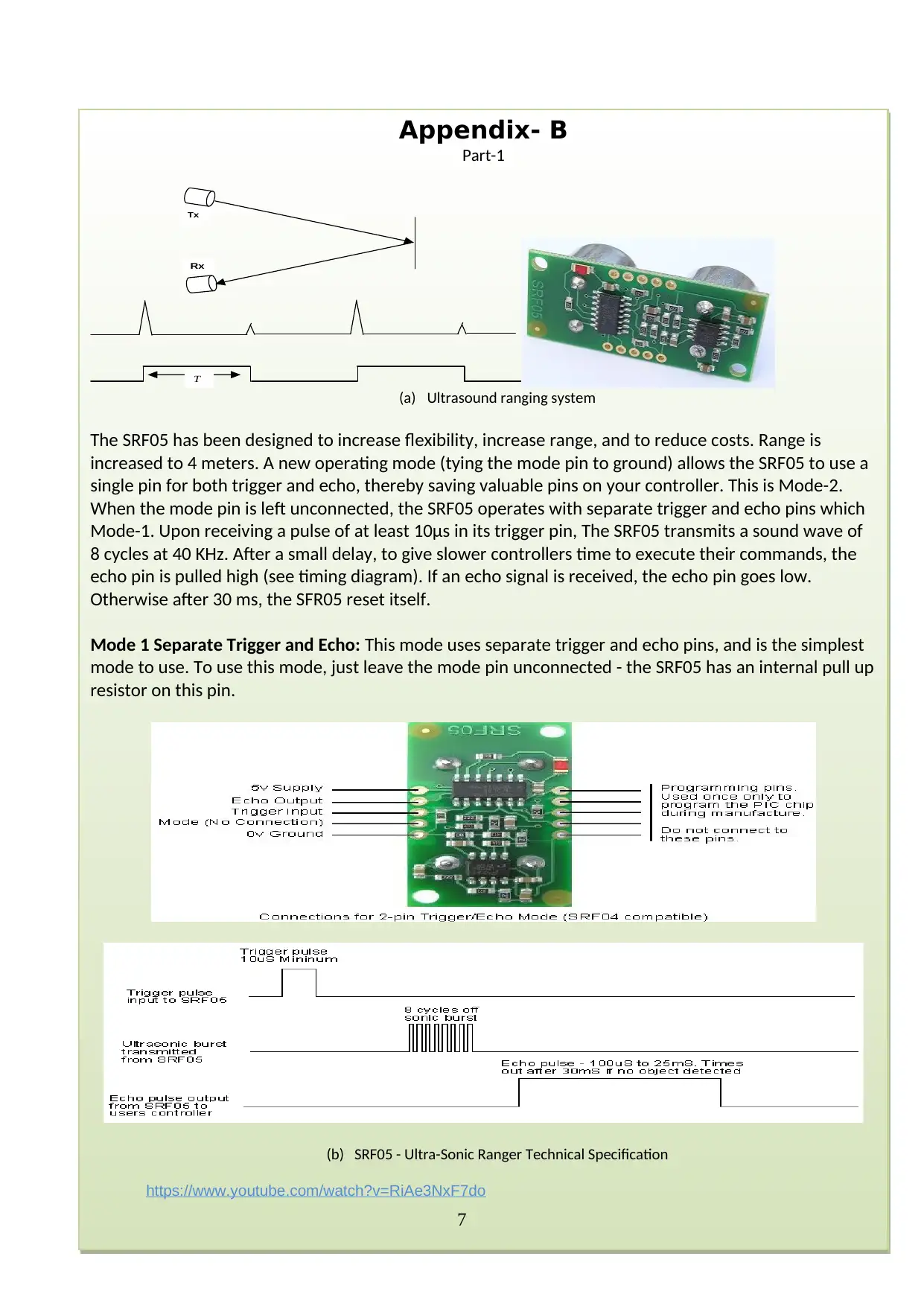
Appendix- B
Part-1
T
Tx
Rx
(a) Ultrasound ranging system
The SRF05 has been designed to increase flexibility, increase range, and to reduce costs. Range is
increased to 4 meters. A new operating mode (tying the mode pin to ground) allows the SRF05 to use a
single pin for both trigger and echo, thereby saving valuable pins on your controller. This is Mode-2.
When the mode pin is left unconnected, the SRF05 operates with separate trigger and echo pins which
Mode-1. Upon receiving a pulse of at least 10μs in its trigger pin, The SRF05 transmits a sound wave of
8 cycles at 40 KHz. After a small delay, to give slower controllers time to execute their commands, the
echo pin is pulled high (see timing diagram). If an echo signal is received, the echo pin goes low.
Otherwise after 30 ms, the SFR05 reset itself.
Mode 1 Separate Trigger and Echo: This mode uses separate trigger and echo pins, and is the simplest
mode to use. To use this mode, just leave the mode pin unconnected - the SRF05 has an internal pull up
resistor on this pin.
(b) SRF05 - Ultra-Sonic Ranger Technical Specification
https://www.youtube.com/watch?v=RiAe3NxF7do
7
Paraphrase This Document
Need a fresh take? Get an instant paraphrase of this document with our AI Paraphraser

8

HONEYWELL S&C - SS59ET - SENSOR, HALL EFFECT, LINEAR, TO-243AA
Links
http://garagelab.com/profiles/blogs/tutorial-how-to-use-the-hall-effect-sensor-with-
arduino
http://homepages.uel.ac.uk/C.Kanesalingam/kanesh.htm
http://www.authorstream.com/Presentation/MarieDigsPpt-1074744-building-a-better-
micromouse/
https://www.youtube.com/watch?v=RiAe3NxF7do
9
Links
http://garagelab.com/profiles/blogs/tutorial-how-to-use-the-hall-effect-sensor-with-
arduino
http://homepages.uel.ac.uk/C.Kanesalingam/kanesh.htm
http://www.authorstream.com/Presentation/MarieDigsPpt-1074744-building-a-better-
micromouse/
https://www.youtube.com/watch?v=RiAe3NxF7do
9
⊘ This is a preview!⊘
Do you want full access?
Subscribe today to unlock all pages.
Trusted by 1+ million students worldwide

Assignment Title: Case study: Set Tasks-
Part-2: Smart Autonomous Bot- Porting with RTOS - μCosIII or alike
Tasks: see attached
Learning Outcomes- http://icis.southwales.ac.uk
LO1. The student will be able to apply formal design methodologies in the development of embedded solutions
LO2: The student will be able to critically analyse an embedded system problem and select the appropriate
design methodology to implement a software solution.
For this assignment, the following learning outcomes supplements should also be taken into account:
LO3.Critically evaluate a User Requirement Specification and identify the appropriate design methodology
required to provide solutions meeting the functionality and requirements defined.
LO4.Will be able to design complex embedded solutions using a pre-emptive RTOS that provide reliable
applications meeting measured hard real time constraints.
Marking Scheme Marks
Awarded
Marks
Available
Task-4-Background search & Design with RTOS μCosIII. Identify the:
(a) Porting features
1. CPU components
2. Libraries components
3. RTOS core components
4. Ports e.g. Renesas processor(s)
5. Source core code components
6. Creating tasks
7. Scheduling and resource management
8. Tasks communications
(b) Board Support Package (BSP) for specific development boards
(Evalboards)
http://micrium.com/rtos/ucosiii/overview/
10
Task-5: Consider the autonomous Bot application developed previously or
similar, using the YRDKRX63N featuring the RX63N microcontroller.
(a) Discuss the disadvantages of such linear/sequential infinite loop approach.
For this, it is advisable to carry out a new analysis of the URS in view of
producing a multitasking system. Inter-task communication should be
considered when required.
(b) In light of the arguments in Task-5, state the advantages of introducing RTOS
in embedded systems
(c) Draw a block diagram/flow diagram showing the changes you intend to
implement to the solution of Part-1 or similar
https://www.youtube.com/watch?v=EmLIHhfEEm4
10
Task-6- Implement the changes (Code in RTOS)
For this code, specify clearly:
Creation of tasks
Organisation of tasks
Communication between tasks
The role of RTOS in the overall control of the application 15
Task-7: Full Report
Write a Full Report 15
Total 100
10
Paraphrase This Document
Need a fresh take? Get an instant paraphrase of this document with our AI Paraphraser

PLEASE NOTE ASPECTS OF YOUR REPORT
Very Well Well Adequately Poorly Very Poorly
Introduction
Methods
Quality of artefact (H/W) and code (S/W)
Analysis, conclusions etc.
Conclusion
Section C : Marker’s Feedback
Lecturer’s Comments:
………………………………………………………………………………………………………………………
………………………………………………………………………………………………………………………
………………………………………………………………………………………………………………………
Areas to concentrate on next time:
Report structure Research Content Team work
Referencing Presentation
Lecturer’s signature: Date: Mark awarded:
All marks are subject to confirmation by the Board of Examiners
11

Attachment
Task-1-Background search & Design with RTOS μCosIII (see Appendix).
Identify:
(a) The Porting features
1. CPU components
2. Libraries components
3. RTOS core components
Ports e.g. Renesas processor(s)
Source core code components
(b) Board Support Package (BSP) for specific development boards (Evalboards)
http://micrium.com/rtos/ucosiii/overview/
(c) General features from the RX 63N microcontroller for porting purposes including:
Initialisations
Creating tasks
Scheduling and resource management
Tasks communications
Advantages and disadvantages of Creating/porting applications with RTOS
Task-2-
Consider the autonomous Bot application developed in Part-1 using the YRDKRX63N
featuring the RX63N microcontroller’
(a) Discuss the disadvantages of such linear/sequential infinite loop approach. For this, it
is advisable to carry out a new analysis of the URS in view of producing a
multitasking system. Inter-task communication should be considered when required.
(b) In light of the arguments in Task-1, state the advantages of introducing RTOS in
embedded systems
(c) Draw a block diagram/flow diagram showing the changes you intend to implement to
the solution Bot application or similar. https://www.youtube.com/watch?
v=EmLIHhfEEm4
Task-3- Implement the changes (Code in RTOS)
For this code, specify clearly:
The Creation of each task
The Organisation of tasks
The Communication between tasks
The role of RTOS in the overall control of the application
Task-4- Write a full report
Advice and details will be explained in meetings.
12
⊘ This is a preview!⊘
Do you want full access?
Subscribe today to unlock all pages.
Trusted by 1+ million students worldwide
1 out of 16
Related Documents


Your All-in-One AI-Powered Toolkit for Academic Success.
+13062052269
info@desklib.com
Available 24*7 on WhatsApp / Email
![[object Object]](/_next/static/media/star-bottom.7253800d.svg)
Unlock your academic potential
Copyright © 2020–2026 A2Z Services. All Rights Reserved. Developed and managed by ZUCOL.