logo

Network Systems Assignment 2017 - VLSM Subnetting Scheme and Network Design

Design and build a network for a new building, considering the number of devices per department and the need for a spare network for HR personnel.

7 Pages1170 Words298 Views
   

Added on  2023-06-16

About This Document

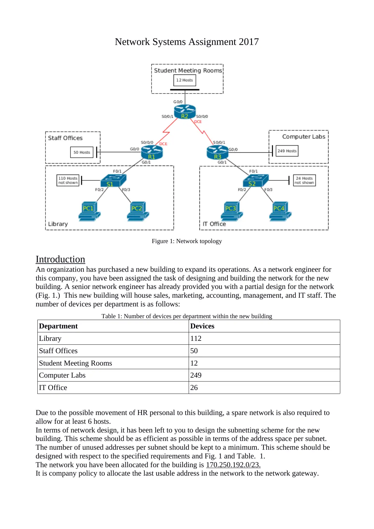
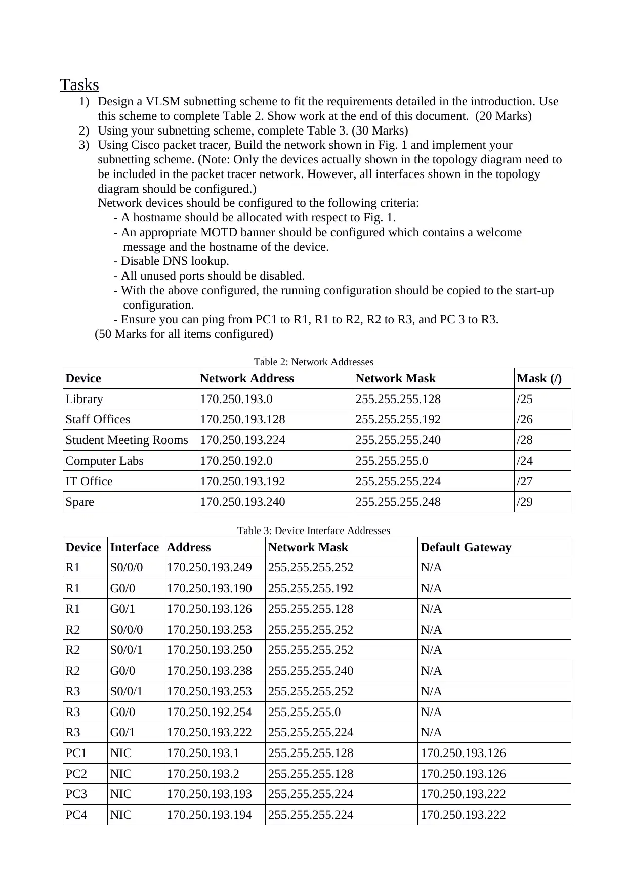
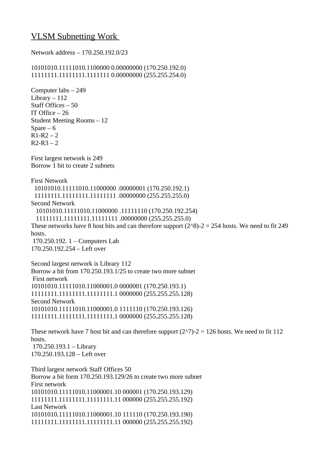
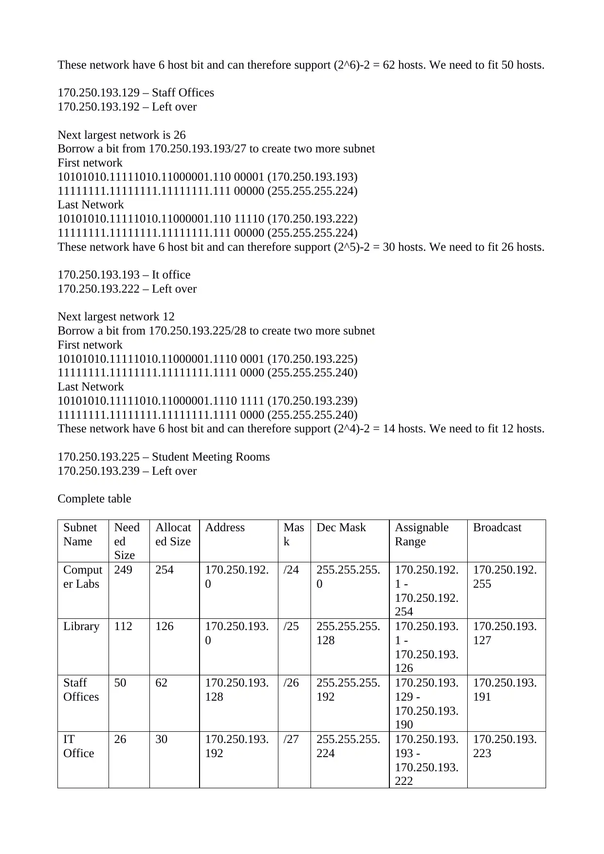
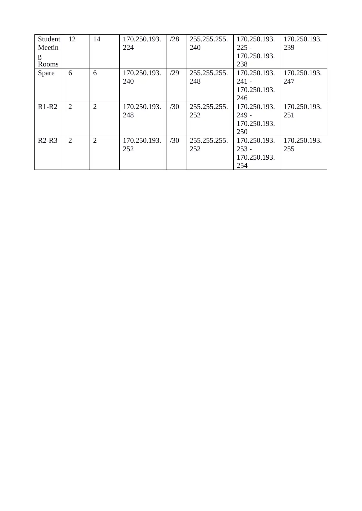
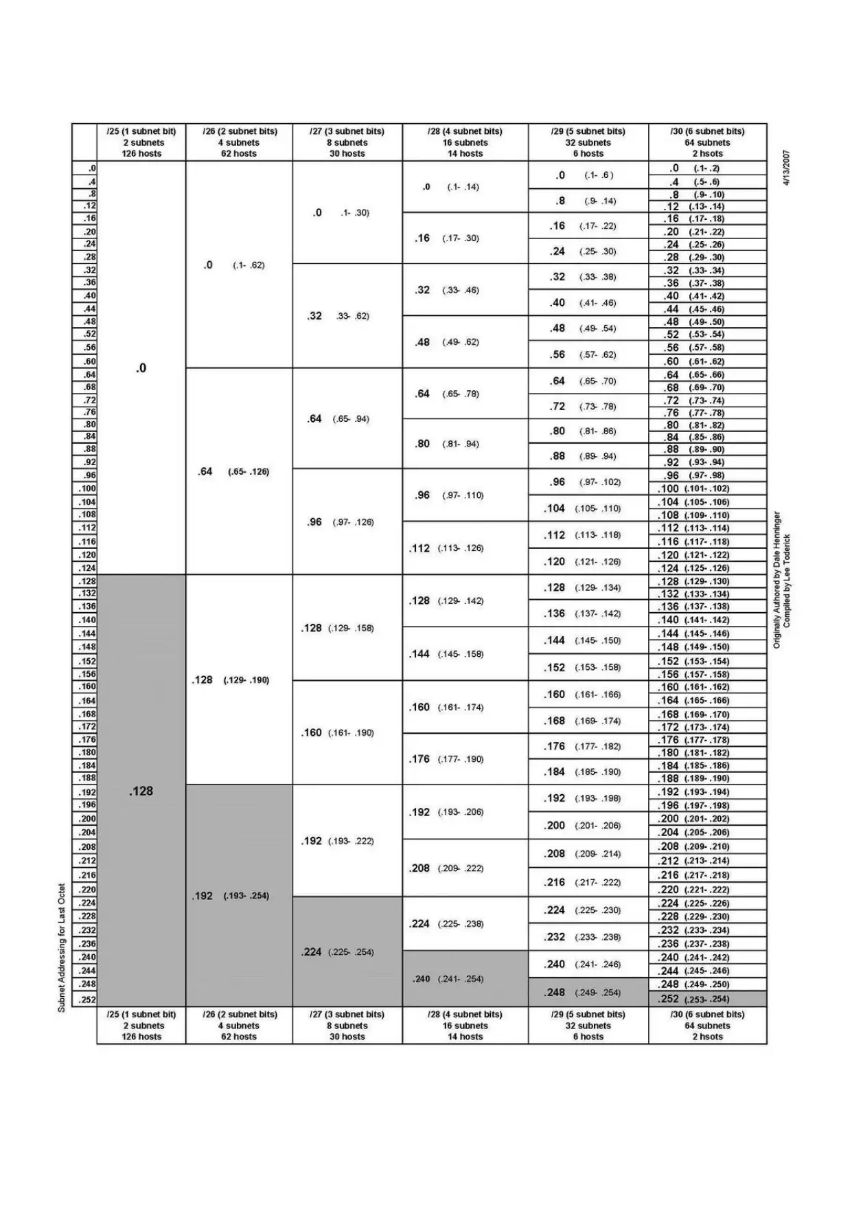
This article discusses the Network Systems Assignment 2017, which involves designing a VLSM subnetting scheme to fit the requirements of a new building and implementing it using Cisco Packet Tracer. The article includes a detailed explanation of the VLSM subnetting work, network addresses, device interface addresses, and tasks involved in building the network. The assignment requires designing a subnetting scheme to fit the requirements of the new building, completing tables with network addresses and device interface addresses, and building the network using Cisco Packet Tracer.

Network Systems Assignment 2017 - VLSM Subnetting Scheme and Network Design

Design and build a network for a new building, considering the number of devices per department and the need for a spare network for HR personnel.

   Added on 2023-06-16

ShareRelated Documents
Network Systems Assignment 2017
Figure 1: Network topology
Introduction
An organization has purchased a new building to expand its operations. As a network engineer for
this company, you have been assigned the task of designing and building the network for the new
building. A senior network engineer has already provided you with a partial design for the network
(Fig. 1.) This new building will house sales, marketing, accounting, management, and IT staff. The
number of devices per department is as follows:
Table 1: Number of devices per department within the new building
Department Devices
Library 112
Staff Offices 50
Student Meeting Rooms 12
Computer Labs 249
IT Office 26
Due to the possible movement of HR personal to this building, a spare network is also required to
allow for at least 6 hosts.
In terms of network design, it has been left to you to design the subnetting scheme for the new
building. This scheme should be as efficient as possible in terms of the address space per subnet.
The number of unused addresses per subnet should be kept to a minimum. This scheme should be
designed with respect to the specified requirements and Fig. 1 and Table. 1.
The network you have been allocated for the building is 170.250.192.0/23.
It is company policy to allocate the last usable address in the network to the network gateway.
Network Systems Assignment 2017 - VLSM Subnetting Scheme and Network Design_1
Tasks
1) Design a VLSM subnetting scheme to fit the requirements detailed in the introduction. Use
this scheme to complete Table 2. Show work at the end of this document. (20 Marks)
2) Using your subnetting scheme, complete Table 3. (30 Marks)
3) Using Cisco packet tracer, Build the network shown in Fig. 1 and implement your
subnetting scheme. (Note: Only the devices actually shown in the topology diagram need to
be included in the packet tracer network. However, all interfaces shown in the topology
diagram should be configured.)
Network devices should be configured to the following criteria:
- A hostname should be allocated with respect to Fig. 1.
- An appropriate MOTD banner should be configured which contains a welcome
message and the hostname of the device.
- Disable DNS lookup.
- All unused ports should be disabled.
- With the above configured, the running configuration should be copied to the start-up
configuration.
- Ensure you can ping from PC1 to R1, R1 to R2, R2 to R3, and PC 3 to R3.
(50 Marks for all items configured)
Table 2: Network Addresses
Device Network Address Network Mask Mask (/)
Library 170.250.193.0 255.255.255.128 /25
Staff Offices 170.250.193.128 255.255.255.192 /26
Student Meeting Rooms 170.250.193.224 255.255.255.240 /28
Computer Labs 170.250.192.0 255.255.255.0 /24
IT Office 170.250.193.192 255.255.255.224 /27
Spare 170.250.193.240 255.255.255.248 /29
Table 3: Device Interface Addresses
Device Interface Address Network Mask Default Gateway
R1 S0/0/0 170.250.193.249 255.255.255.252 N/A
R1 G0/0 170.250.193.190 255.255.255.192 N/A
R1 G0/1 170.250.193.126 255.255.255.128 N/A
R2 S0/0/0 170.250.193.253 255.255.255.252 N/A
R2 S0/0/1 170.250.193.250 255.255.255.252 N/A
R2 G0/0 170.250.193.238 255.255.255.240 N/A
R3 S0/0/1 170.250.193.253 255.255.255.252 N/A
R3 G0/0 170.250.192.254 255.255.255.0 N/A
R3 G0/1 170.250.193.222 255.255.255.224 N/A
PC1 NIC 170.250.193.1 255.255.255.128 170.250.193.126
PC2 NIC 170.250.193.2 255.255.255.128 170.250.193.126
PC3 NIC 170.250.193.193 255.255.255.224 170.250.193.222
PC4 NIC 170.250.193.194 255.255.255.224 170.250.193.222
Network Systems Assignment 2017 - VLSM Subnetting Scheme and Network Design_2
VLSM Subnetting Work
Network address – 170.250.192.0/23
10101010.11111010.1100000 0.00000000 (170.250.192.0)
11111111.11111111.1111111 0.00000000 (255.255.254.0)
Computer labs – 249
Library – 112
Staff Offices – 50
IT Office – 26
Student Meeting Rooms – 12
Spare – 6
R1-R2 – 2
R2-R3 – 2
First largest network is 249
Borrow 1 bit to create 2 subnets
First Network
10101010.11111010.11000000 .00000001 (170.250.192.1)
11111111.11111111.11111111 .00000000 (255.255.255.0)
Second Network
10101010.11111010.11000000 .11111110 (170.250.192.254)
11111111.11111111.11111111 .00000000 (255.255.255.0)
These networks have 8 host bits and can therefore support (2^8)-2 = 254 hosts. We need to fit 249
hosts.
170.250.192. 1 – Computers Lab
170.250.192.254 – Left over
Second largest network is Library 112
Borrow a bit from 170.250.193.1/25 to create two more subnet
First network
10101010.11111010.11000001.0 0000001 (170.250.193.1)
11111111.11111111.11111111.1 0000000 (255.255.255.128)
Second Network
10101010.11111010.11000001.0 1111110 (170.250.193.126)
11111111.11111111.11111111.1 0000000 (255.255.255.128)
These network have 7 host bit and can therefore support (2^7)-2 = 126 hosts. We need to fit 112
hosts.
170.250.193.1 – Library
170.250.193.128 – Left over
Third largest network Staff Offices 50
Borrow a bit form 170.250.193.129/26 to create two more subnet
First network
10101010.11111010.11000001.10 000001 (170.250.193.129)
11111111.11111111.11111111.11 000000 (255.255.255.192)
Last Network
10101010.11111010.11000001.10 111110 (170.250.193.190)
11111111.11111111.11111111.11 000000 (255.255.255.192)
Network Systems Assignment 2017 - VLSM Subnetting Scheme and Network Design_3

End of preview

Want to access all the pages? Upload your documents or become a member.

Related Documents
CCE3060 Lab Test 4
|6
|1242
|97

Lab: Configuring BGP Routing
|2
|627
|393

Primary School Network Design with Guest Network
|16
|1462
|361

Addressing Scheme and Basic Configuration for Campus Network
|14
|1001
|394

Network Review for SEC 6040: Web and Data Security
|5
|753
|488

Designing Primary School Network with DHCP, Access List and Server Configuration
|17
|1280
|346