IEEE Report on Power Amplifier PAE: Components, Classification & Apps
VerifiedAdded on 2023/06/15
|6
|3234
|53
Report
AI Summary
This report provides an overview of Power Amplifiers (PAs), focusing on Power Added Efficiency (PAE), components, and classification. It details different classes of power amplifiers, including Class A, B, AB, C, D, E, F, G, and H, highlighting their characteristics, advantages, disadvantages, and applications. The report covers conduction angles, linearity, efficiency, and distortion levels for each class. Class A amplifiers offer high linearity but low efficiency, while Class B amplifiers improve efficiency but introduce distortion. Class AB amplifiers combine aspects of both, and Class C amplifiers are suitable for radio frequency applications. Switching amplifiers like Class D and E are also discussed. The report includes waveform comparisons and schematics to illustrate the operation of each class, emphasizing the trade-offs between efficiency and linearity in power amplifier design. Desklib offers a platform for students to access this and other solved assignments.
Abstract – This paper represents a brief concept of Power Amplifier its components, classification from type Class A, B, AB,
C, D along with additional type E, F and G, H. Amplifier that amplifies the current signal in order to drive output. It draws
electric power from source that is a power supply in order to increase amplitude of disturb signal. There are certain classes;
those are differentiated by passing current through a time period. The classes in power amplifier are A, B, C along with AB
are specially designed for analog applications, while classes of power amplifier D along with E,F serve the purpose as
switching device. PAE have multiple states as they are in cascade system, the sole purpose is to increase gain.
Index Terms— CMOS, RF, PWM, PAE. ADS, Tx, Rx, BJT, FET, APRL
I. INTRODUCTION1
MPLIFIER circuit are the basis of the mainly
electronics systems, as they use to drive output by
producing high power[1]. An amplifier uses electric power
to increase amplitude of the signal. It gains it from power
supply. The amplification performed by the amplifier is
measured by gain considering ratio of output to given i/p
input this could be voltage or current. Dc amplifier uses
control system of electronics also needed power to drive
actuators or motors. Power Amplifier is distinguished by a
higher power at least greater than one. An amplifier
modulates output result property on the basis of given
input signal property. Amplifiers are usually comes in
every electronic devices [17]. Amplifier is further
classified into different types. Frequency enhancements or
improvement is the first one. The second one is an audio
amplifier that amplifies the signal in less than 20 KHz
while a RF amplifier amplifies in between a range of 20
KHz to 300 KHz [2]. The last one is a Power Amplifier
PAE for improving quality of current or voltage. Power
amplifier are being divided into these types A, B, C, along
with C that are use for improving analog design. D and E,
F are used for switching designs. Conduction Cycle is the
proportion of each input cycle occurs when an input signal
passes current through an amplifying device.
A
II.CLASSIFICATION OF POWER AMPLIFIER
A. Class A
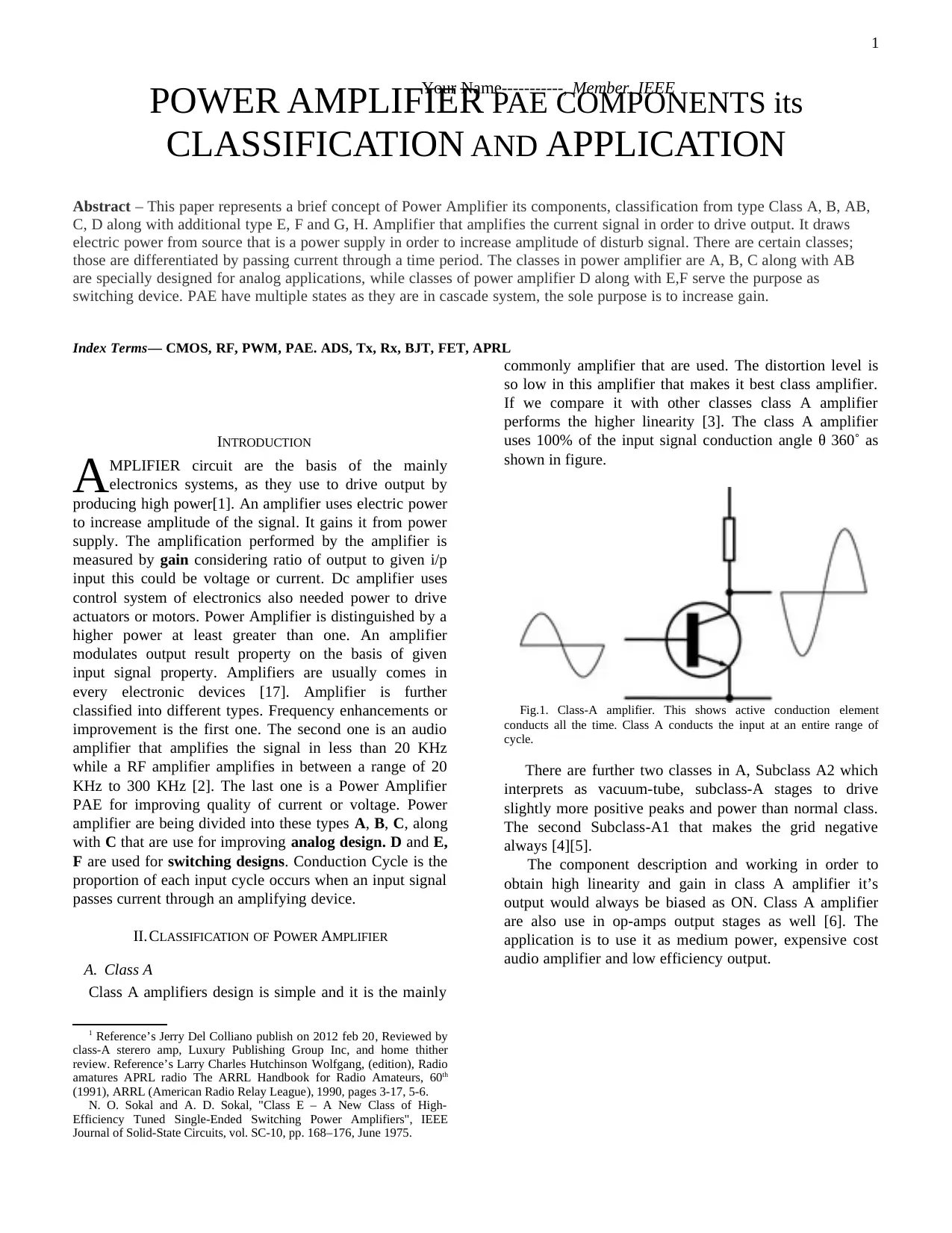
Class A amplifiers design is simple and it is the mainly
1 Reference’s Jerry Del Colliano publish on 2012 feb 20, Reviewed by
class-A sterero amp, Luxury Publishing Group Inc, and home thither
review. Reference’s Larry Charles Hutchinson Wolfgang, (edition), Radio
amatures APRL radio The ARRL Handbook for Radio Amateurs, 60th
(1991), ARRL (American Radio Relay League), 1990, pages 3-17, 5-6.
N. O. Sokal and A. D. Sokal, "Class E – A New Class of High-
Efficiency Tuned Single-Ended Switching Power Amplifiers", IEEE
Journal of Solid-State Circuits, vol. SC-10, pp. 168–176, June 1975.
commonly amplifier that are used. The distortion level is
so low in this amplifier that makes it best class amplifier.
If we compare it with other classes class A amplifier
performs the higher linearity [3]. The class A amplifier
uses 100% of the input signal conduction angle θ 360˚ as
shown in figure.
Fig.1. Class-A amplifier. This shows active conduction element
conducts all the time. Class A conducts the input at an entire range of
cycle.
There are further two classes in A, Subclass A2 which
interprets as vacuum-tube, subclass-A stages to drive
slightly more positive peaks and power than normal class.
The second Subclass-A1 that makes the grid negative
always [4][5].
The component description and working in order to
obtain high linearity and gain in class A amplifier it’s
output would always be biased as ON. Class A amplifier
are also use in op-amps output stages as well [6]. The
application is to use it as medium power, expensive cost
audio amplifier and low efficiency output.
POWER AMPLIFIER PAE COMPONENTS its
CLASSIFICATION AND APPLICATION
Your Name-----------, Member, IEEE
1
Paraphrase This Document
Need a fresh take? Get an instant paraphrase of this document with our AI Paraphraser
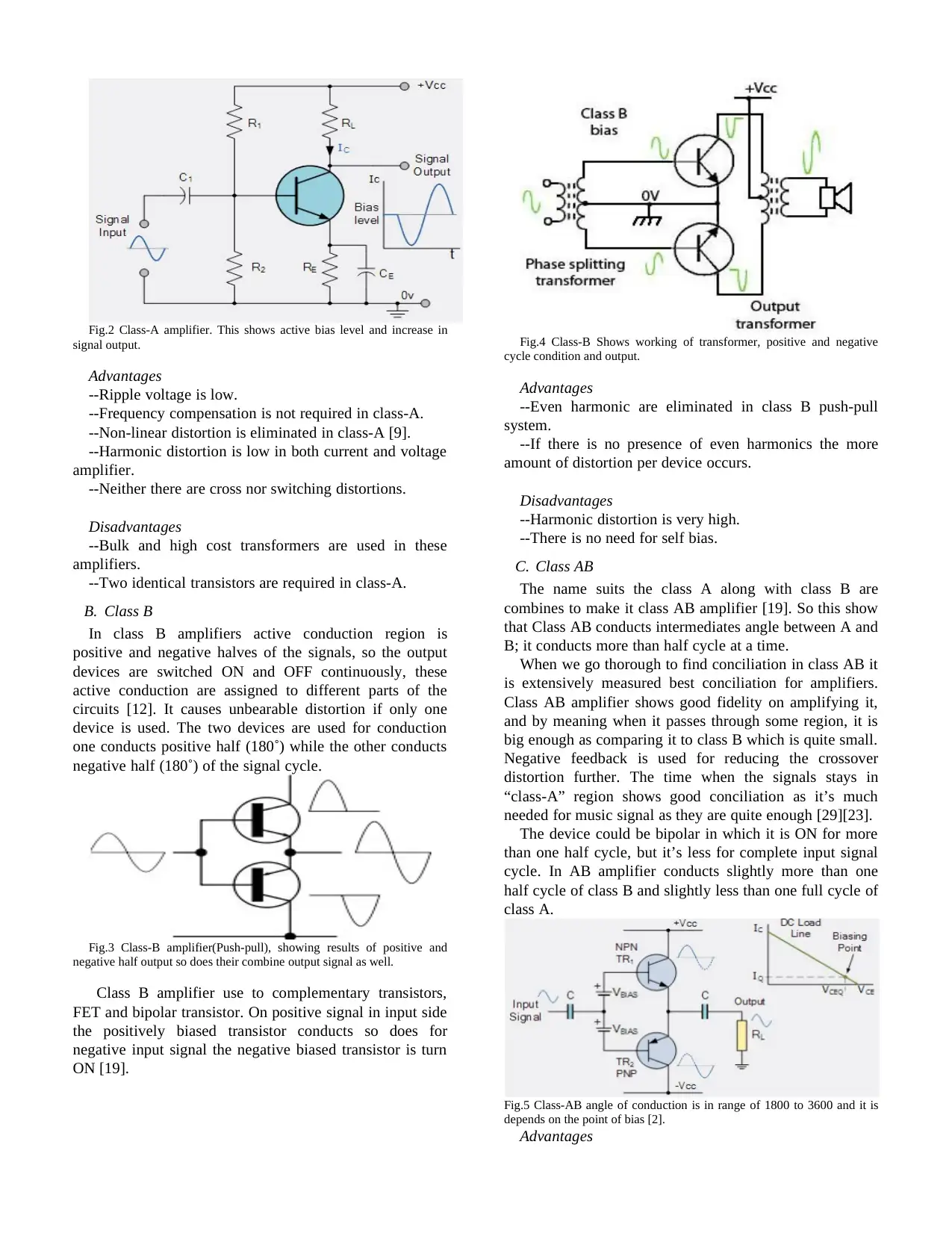
Fig.2 Class-A amplifier. This shows active bias level and increase in
signal output.
Advantages
--Ripple voltage is low.
--Frequency compensation is not required in class-A.
--Non-linear distortion is eliminated in class-A [9].
--Harmonic distortion is low in both current and voltage
amplifier.
--Neither there are cross nor switching distortions.
Disadvantages
--Bulk and high cost transformers are used in these
amplifiers.
--Two identical transistors are required in class-A.
B. Class B
In class B amplifiers active conduction region is
positive and negative halves of the signals, so the output
devices are switched ON and OFF continuously, these
active conduction are assigned to different parts of the
circuits [12]. It causes unbearable distortion if only one
device is used. The two devices are used for conduction
one conducts positive half (180˚) while the other conducts
negative half (180˚) of the signal cycle.
Fig.3 Class-B amplifier(Push-pull), showing results of positive and
negative half output so does their combine output signal as well.
Class B amplifier use to complementary transistors,
FET and bipolar transistor. On positive signal in input side
the positively biased transistor conducts so does for
negative input signal the negative biased transistor is turn
ON [19].
Fig.4 Class-B Shows working of transformer, positive and negative
cycle condition and output.
Advantages
--Even harmonic are eliminated in class B push-pull
system.
--If there is no presence of even harmonics the more
amount of distortion per device occurs.
Disadvantages
--Harmonic distortion is very high.
--There is no need for self bias.
C. Class AB
The name suits the class A along with class B are
combines to make it class AB amplifier [19]. So this show
that Class AB conducts intermediates angle between A and
B; it conducts more than half cycle at a time.
When we go thorough to find conciliation in class AB it
is extensively measured best conciliation for amplifiers.
Class AB amplifier shows good fidelity on amplifying it,
and by meaning when it passes through some region, it is
big enough as comparing it to class B which is quite small.
Negative feedback is used for reducing the crossover
distortion further. The time when the signals stays in
“class-A” region shows good conciliation as it’s much
needed for music signal as they are quite enough [29][23].
The device could be bipolar in which it is ON for more
than one half cycle, but it’s less for complete input signal
cycle. In AB amplifier conducts slightly more than one
half cycle of class B and slightly less than one full cycle of
class A.
Fig.5 Class-AB angle of conduction is in range of 1800 to 3600 and it is
depends on the point of bias [2].
Advantages
--It has linear behavior.
--It has a simple design.
--The distortion is approximately negligible.
--High quality sound is produce.
Disadvantages
--PAE generates massive amount of heat it requires heat
sink for heat dissipation.
--Efficiency is 50% less.
D. Class C
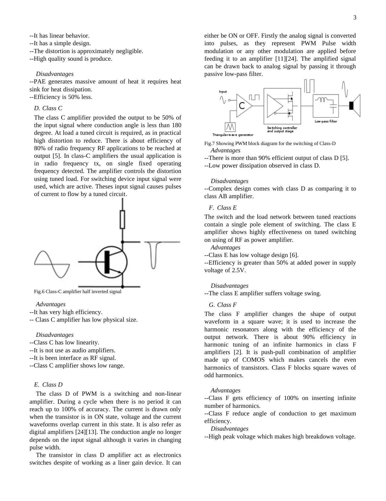
The class C amplifier provided the output to be 50% of
the input signal where conduction angle is less than 180
degree. At load a tuned circuit is required, as in practical
high distortion to reduce. There is about efficiency of
80% of radio frequency RF applications to be reached at
output [5]. In class-C amplifiers the usual application is
in radio frequency tx, on single fixed operating
frequency detected. The amplifier controls the distortion
using tuned load. For switching device input signal were
used, which are active. Theses input signal causes pulses
of current to flow by a tuned circuit.
Fig.6 Class-C amplifier half inverted signal
Advantages
--It has very high efficiency.
-- Class C amplifier has low physical size.
Disadvantages
--Class C has low linearity.
--It is not use as audio amplifiers.
--It is been interface as RF signal.
--Class C amplifier shows low range.
E. Class D
The class D of PWM is a switching and non-linear
amplifier. During a cycle when there is no period it can
reach up to 100% of accuracy. The current is drawn only
when the transistor is in ON state, voltage and the current
waveforms overlap current in this state. It is also refer as
digital amplifiers [24][13]. The conduction angle no longer
depends on the input signal although it varies in changing
pulse width.
The transistor in class D amplifier act as electronics
switches despite of working as a liner gain device. It can
either be ON or OFF. Firstly the analog signal is converted
into pulses, as they represent PWM Pulse width
modulation or any other modulation are applied before
feeding it to an amplifier [11][24]. The amplified signal
can be drawn back to analog signal by passing it through
passive low-pass filter.
Fig.7 Showing PWM block diagram for the switching of Class-D
Advantages
--There is more than 90% efficient output of class D [5].
--Low power dissipation observed in class D.
Disadvantages
--Complex design comes with class D as comparing it to
class AB amplifier.
F. Class E
The switch and the load network between tuned reactions
contain a single pole element of switching. The class E
amplifier shows highly effectiveness on tuned switching
on using of RF as power amplifier.
Advantages
--Class E has low voltage design [6].
--Efficiency is greater than 50% at added power in supply
voltage of 2.5V.
Disadvantages
--The class E amplifier suffers voltage swing.
G. Class F
The class F amplifier changes the shape of output
waveform in a square wave; it is used to increase the
harmonic resonators along with the efficiency of the
output network. There is about 90% efficiency in
harmonic tuning of an infinite harmonics in class F
amplifiers [2]. It is push-pull combination of amplifier
made up of COMOS which makes cancels the even
harmonics of transistors. Class F blocks square waves of
odd harmonics.
Advantages
--Class F gets efficiency of 100% on inserting infinite
number of harmonics.
--Class F reduce angle of conduction to get maximum
efficiency.
Disadvantages
--High peak voltage which makes high breakdown voltage.
3
⊘ This is a preview!⊘
Do you want full access?
Subscribe today to unlock all pages.

Trusted by 1+ million students worldwide
III. POWER AMPLIFIERS CLASSES
Power amplifiers badly designed of the following classes
require power transistor of large size, heat sinks require for
heat dissipation. Furthermore illustration can be seen in
table. They also require power supply with large size to
drive the amplifier with extra amount of power especially
in class A [17]. If this amplifier does uses heat sink power
converted back to transistor, causes loss in efficiency.
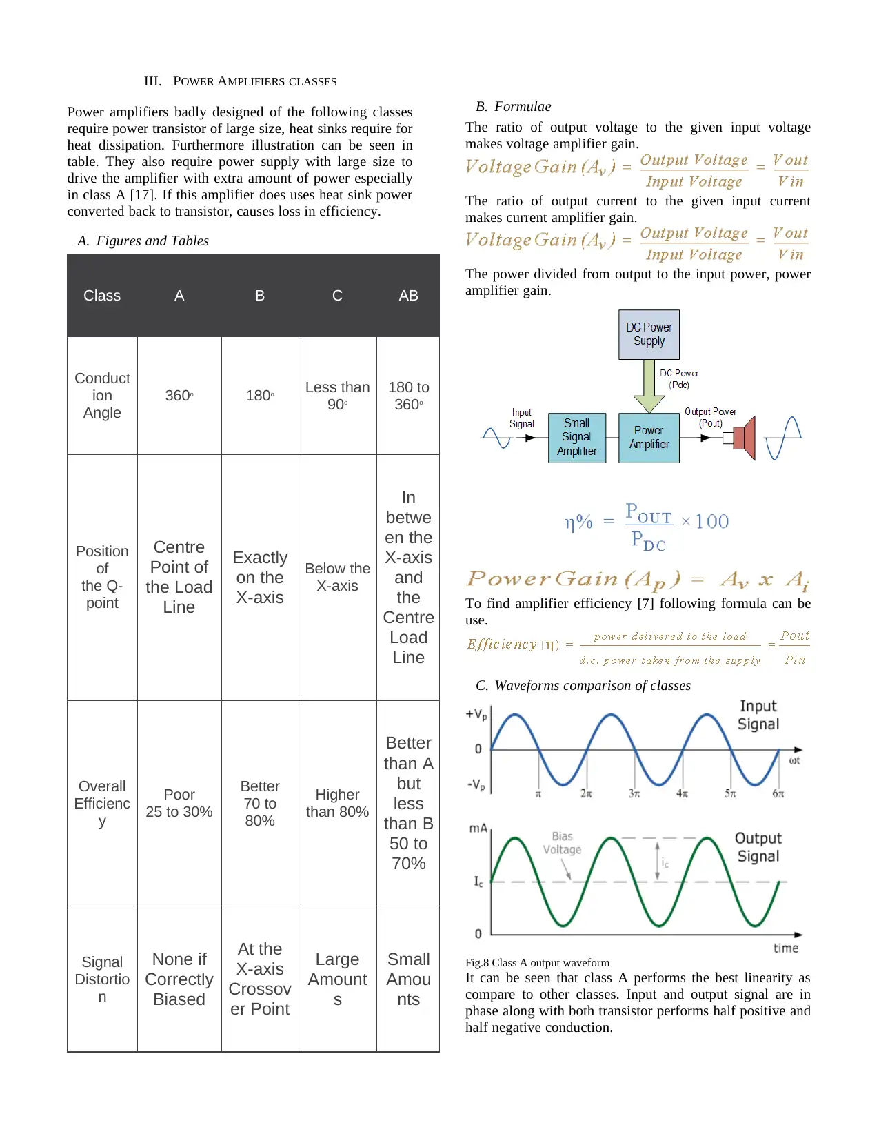
A. Figures and Tables
Class A B C AB
Conduct
ion
Angle
360o 180o Less than
90o
180 to
360o
Position
of
the Q-
point
Centre
Point of
the Load
Line
Exactly
on the
X-axis
Below the
X-axis
In
betwe
en the
X-axis
and
the
Centre
Load
Line
Overall
Efficienc
y
Poor
25 to 30%
Better
70 to
80%
Higher
than 80%
Better
than A
but
less
than B
50 to
70%
Signal
Distortio
n
None if
Correctly
Biased
At the
X-axis
Crossov
er Point
Large
Amount
s
Small
Amou
nts
B. Formulae
The ratio of output voltage to the given input voltage
makes voltage amplifier gain.
The ratio of output current to the given input current
makes current amplifier gain.
The power divided from output to the input power, power
amplifier gain.
To find amplifier efficiency [7] following formula can be
use.
C. Waveforms comparison of classes
Fig.8 Class A output waveform
It can be seen that class A performs the best linearity as
compare to other classes. Input and output signal are in
phase along with both transistor performs half positive and
half negative conduction.
Paraphrase This Document
Need a fresh take? Get an instant paraphrase of this document with our AI Paraphraser
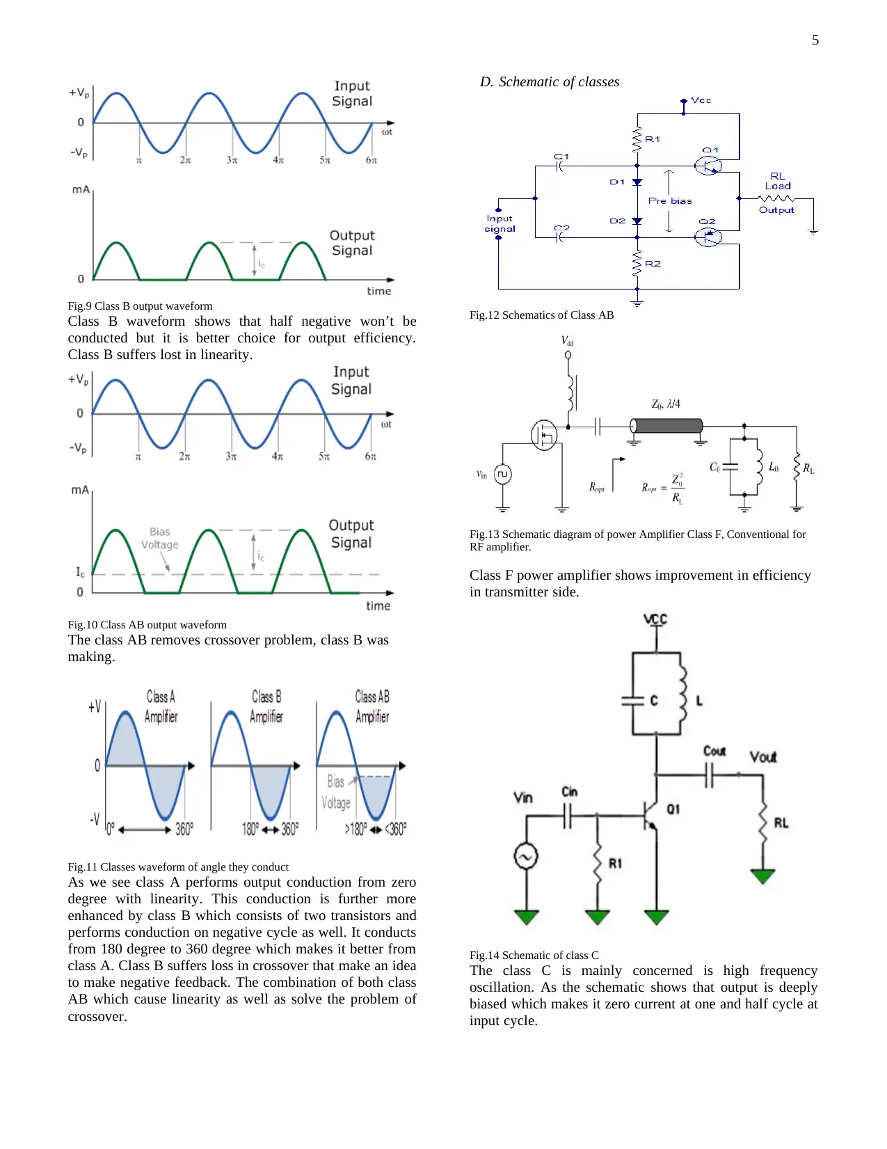
Fig.9 Class B output waveform
Class B waveform shows that half negative won’t be
conducted but it is better choice for output efficiency.
Class B suffers lost in linearity.
Fig.10 Class AB output waveform
The class AB removes crossover problem, class B was
making.
Fig.11 Classes waveform of angle they conduct
As we see class A performs output conduction from zero
degree with linearity. This conduction is further more
enhanced by class B which consists of two transistors and
performs conduction on negative cycle as well. It conducts
from 180 degree to 360 degree which makes it better from
class A. Class B suffers loss in crossover that make an idea
to make negative feedback. The combination of both class
AB which cause linearity as well as solve the problem of
crossover.
D. Schematic of classes
Fig.12 Schematics of Class AB
Fig.13 Schematic diagram of power Amplifier Class F, Conventional for
RF amplifier.
Class F power amplifier shows improvement in efficiency
in transmitter side.
Fig.14 Schematic of class C
The class C is mainly concerned is high frequency
oscillation. As the schematic shows that output is deeply
biased which makes it zero current at one and half cycle at
input cycle.
5
IV. CONCLUSION
Amplifier are preferably used in every electronics
circuits in order to remove power dissipation along with
amplify sound, current, voltage as required. Transistors
were assume to be identical this makes reduction in even
harmonics many times there was none-harmonic. Every
class has its own unique property which makes it to use for
special applications. As it can be seen class B was found to
be more efficient than class A, but loses its linearity. Class
B amplifier makes crossover distortion which leads it to
class AB amplifier.
REFERENCES
[1] http://www.learnabout-electronics.org/Amplifiers/amplifiers50.php
[2] https://www.elprocus.com/classification-of-amplifiers-classes-its-
applications/
[3] ARRL Handbook, 1968; page 65
[4] "Amplifier classes". www.duncanamps.com. Retrieved 2016-06-20.
[5] "Class D Amplifiers: Fundamentals of Operation and Recent
Developments - Application Note - Maxim".
www.maximintegrated.com. Retrieved 2016-06-20.
[6] IEEE Journal of Solid-State Circuits ( Volume: 30, Issue: 10, Oct
1995 )
[7] https://www.electronics-tutorials.ws/amplifier/amp_1.html
[8] https://www.electronics-tutorials.ws/amplifier/amp_1.html
[9] https://www.researchgate.net/publication/
224238647_Remote_laboratory_exercise_for_class_BAB_power_a
mplifier.
[10] https://www.electronics-tutorials.ws/amplifier/amp_1.html
[11] Jerry Del Colliano (20 February 2012), Pass Labs XA30.5 Class-A
Stereo Amp Reviewed, Home Theater Review, Luxury Publishing
Group Inc.
[12] Larry Wolfgang, Charles Hutchinson (ed), The ARRL Handbook for
Radio Amateurs, Sixty-Eighth Edition (1991), American Radio Relay
League, 1990, ISBN 0-87259-168-9, pages 3-17, 5-6,
[13] "Class B Amplifier - Class-B Transistor Amplifier Electronic
Amplifier Tutorial". Basic Electronics Tutorials. 2013-07-25.
Retrieved 2016-06-20.
[14] Tuite, Don (March 21, 2012). "Understanding Amplifier Classes".
Electronic Design (March, 2012).
[15] "Class AB Power Amplifiers". www.learnabout-electronics.org.
Retrieved 2016-06-20.
[16] "Class C power amplifier circuit diagram and theory. Output
characteristics DC load line". www.circuitstoday.com. Retrieved
2016-06-20.
[17] N. O. Sokal and A. D. Sokal, "Class E – A New Class of High-
Efficiency Tuned Single-Ended Switching Power Amplifiers", IEEE
Journal of Solid-State Circuits, vol. SC-10, pp. 168–176, June 1975.
[18] S. P. Bingulac, “On the compatibility of adaptive controllers
(Published Conference Proceedings style),” in Proc. 4th Annu.
Allerton Conf. Circuits and Systems Theory, New York, 1994, pp. 8–
16.
[19] http://projekter.aau.dk/projekter/files/16485128/
rapport_pa_modifie__v9.pdf
[20] http://citeseerx.ist.psu.edu/viewdoc/download?
doi=10.1.1.184.4037&rep=rep1&type=pdf.
[21] https://www.researchgate.net/publication/
224238647_Remote_laboratory_exercise_for_class_BAB_power_a
mplifier
[22] Mihai Albulet, RF Power Amplifiers, SciTech Publishing, 2001,
ISBN 1884932126 pages 216-220
[23] N. O. Sokal and A. D. Sokal, "Class E – A New Class of High-
Efficiency Tuned Single-Ended Switching Power Amplifiers", IEEE
Journal of Solid-State Circuits, vol. SC-10, pp. 168–176, June 1975.
[24] Patronis, Gene (1987). "Amplifiers". In Glen Ballou. Handbook for
Sound Engineers: The New Audio Cyclopedia. Howard W. Sams &
Co. p. 493. ISBN 0-672-21983-2.
[25] De Forest, Lee (January 1906). "The Audion; A New Receiver for
Wireless Telegraphy". Trans. of the AIEE. American Institute of
Electrical and Electronic Engineers. 25: 735–763. doi:10.1109/t-
aiee.1906.4764762. Retrieved January 7, 2013. The link is to a
reprint of the paper in the Scientific American Supplement, No.
1665, November 30, 1907, p.348-350, copied on Thomas H. White's
United States Early Radio History website
[26] Crecraft, David; Gorham, David (2003). Electronics, 2nd Ed. CRC
Press. p. 168. ISBN 0748770364.
[27] Agarwal, Anant; Lang, Jeffrey (2005). Foundations of Analog and
Digital Electronic Circuits. Morgan Kaufmann. p. 331. ISBN
008050681X.
[28] Glisson, Tildon H. (2011). Introduction to Circuit Analysis and
Design. Springer Science and Business Media. ISBN 9048194431.
[29] Harper, Douglas (2001). "Amplify". Online Etymology Dictionary.
Etymonline.com. Retrieved July 10, 2015.
[30] Albert A.L., Electrical Communication, 3rd edition, Wiley (1954),
p.13
⊘ This is a preview!⊘
Do you want full access?
Subscribe today to unlock all pages.

Trusted by 1+ million students worldwide
1 out of 6
Related Documents
Your All-in-One AI-Powered Toolkit for Academic Success.
+13062052269
info@desklib.com
Available 24*7 on WhatsApp / Email
![[object Object]](/_next/static/media/star-bottom.7253800d.svg)
Unlock your academic potential
Copyright © 2020–2026 A2Z Services. All Rights Reserved. Developed and managed by ZUCOL.


