Transfer Function of First Order Control Systems

Verified

Added on  2022/10/11

|5
|910
|97
AI Summary
This article explains the transfer function of first order control systems and its significance in determining the type and order of a control system. It also covers the process of drawing frequency response, Nyquist, Root locus, Nichols and bode plots using the transfer function. The article also discusses the effect of increasing b on the stability of the system.

Contribute Materials

Your contribution can guide someone’s learning journey. Share your documents today.
Document Page
Question one
Equation 2 is the transfer function of first order control systems. A transfer function describes the
relationship between the input and the output. In equation 2, X(s) is the input to the system and
Y(s) is the output. A transfer function helps in determining the type and the order of a control
system. Furthermore, frequency response of the control system, Nyquist, Root locus, Nichols and
bode plots can be drawn using the transfer function. The plots provide information that is useful
in study and analysis of control systems, for example information on stability of the system. The
denominator of the transfer function gives the characteristic equation, it is from the characteristic
equation that the roots of the system is derived.
Question two
First order transfer function of the system, T(s) is given by
T(s) = Y ( s)
X (s) = c
ds+1 ……………………………2
Y (s) = T (s) * X (s), but T(s) = c
ds+1 thus
= c
ds+1 * X (s)………………………..….3
Since the input is the unit step function, X(s) = 1/s. substituting for X (s) in equation 3 we get
Y(s) =
1
s c
(ds +1)
……………………………….4
Rearranging equation 4 we get
Y(s) =
1
s c
d(s +1/d )
Y(s) =
1
s c /d
( s+1/d )
………………………………..5
Decomposing equation 5 using partial fraction gives
Y (s) = c / d
s (s +1/d ) ¿ A
s + B
s+1/d ……………………6
A = c /d
s (s +1/d )s=¿ { c /d
( s+1 /d ) } s=0 = c

Secure Best Marks with AI Grader

Need help grading? Try our AI Grader for instant feedback on your assignments.
Document Page
B = c /d
s (s +1/d )( s+1/d )={ c /d
s }s=-1/d= -c
Y (s) = c
s c
s+1/ d = c { 1
s 1
s+ 1
d
}………….……...7
Taking inverse Laplace transform of equation 7 we get
y(t) = c – c * exp{-(1/d)t},
y (t) = c{1-e-(1/d)t} …………………..………8
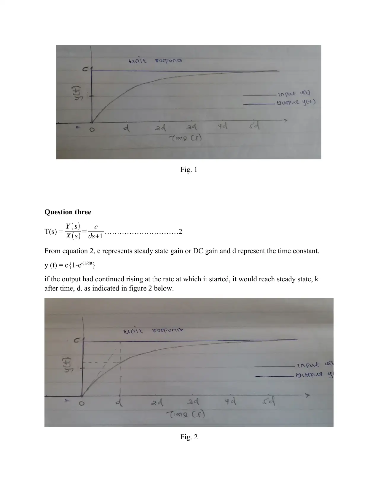
when t = 0, y (t) = c{1-e-0} = 0
when t = 1d, y(t) = c{1-e-1} = 0.632c
when t = 2d, y (t) = c{1-e-2} = 0.864c
when t = 3d, y (t) = c{1-e-3} = 0.950c
when t = 4d, y (t) = c{1-e-4} = 0.982c
when t = 5d, y (t) = c{1-e-5} = 0.993c
when t = , y (t) = c{1-e-} = c
y (t) is explicitly zero when t is less than 1
Tabulating the information above:
t y(t)
0 0
1d 0.632c
2d 0.864c
3d 0.950c
4d 0.982c
5d 0.993c
c
Table 1
u (t) = 1 when t is equal or greater than 1
u (t) = 0 when t is less than 1
Document Page
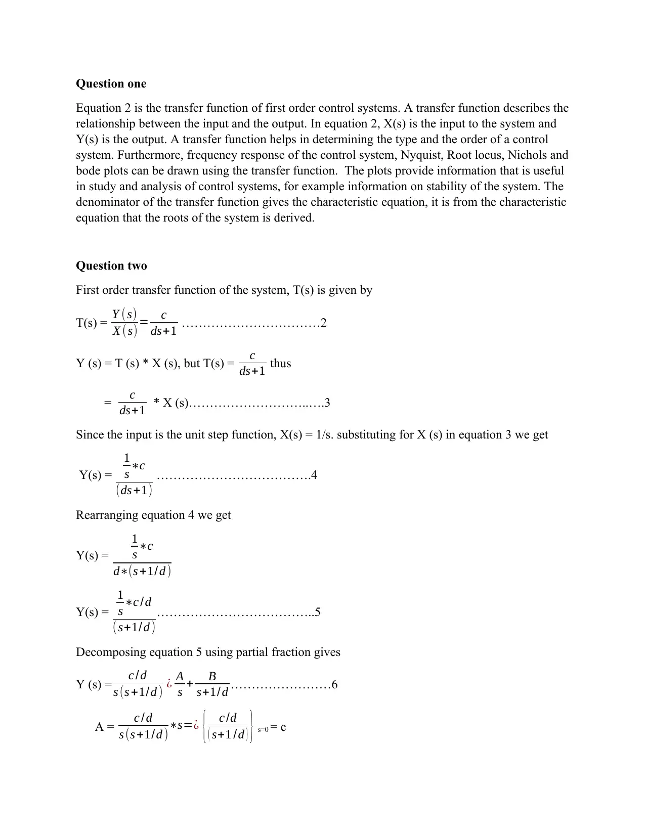
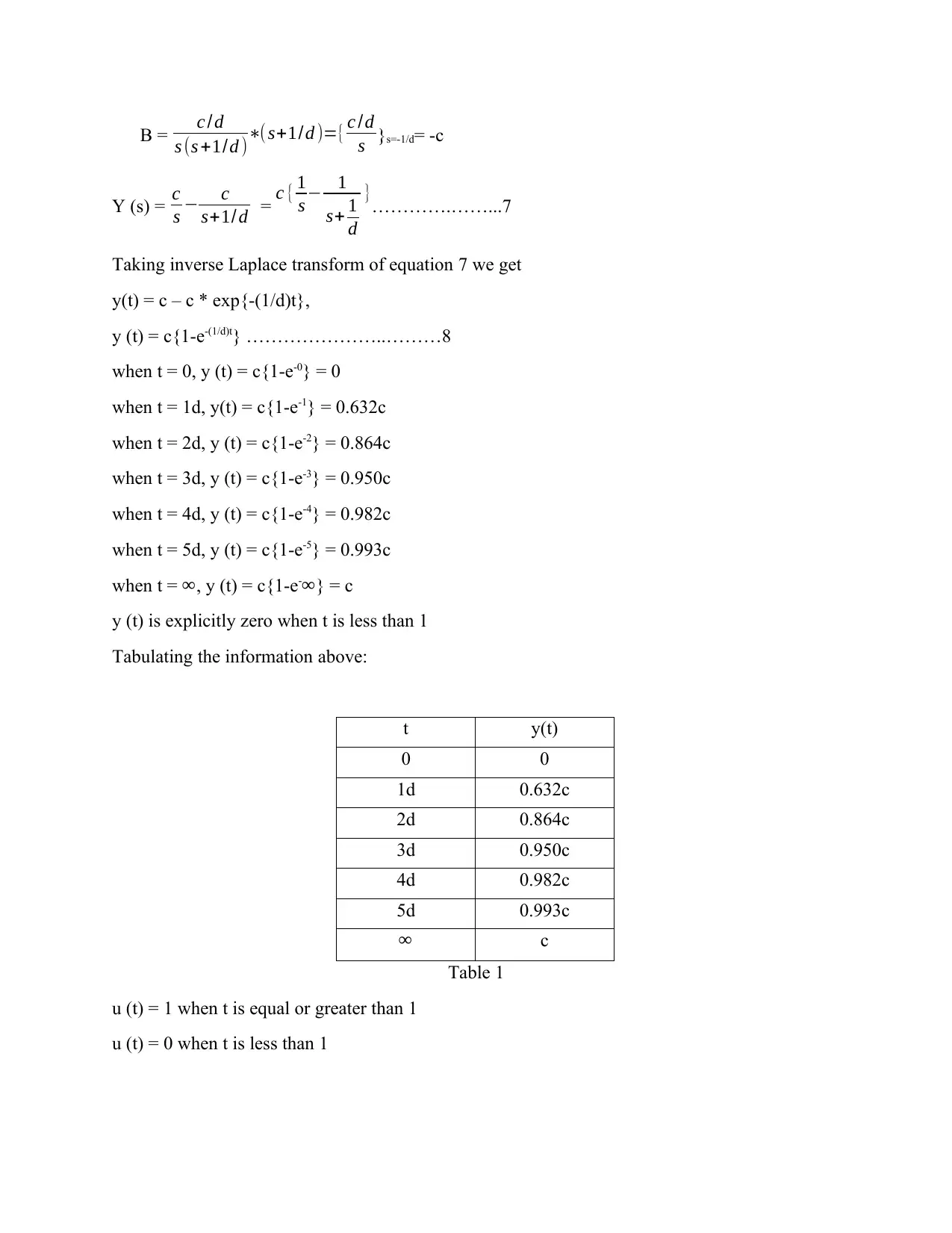
Fig. 1
Question three
T(s) = Y ( s)
X (s) = c
ds+1 …………………………2
From equation 2, c represents steady state gain or DC gain and d represent the time constant.
y (t) = c{1-e-(1/d)t}
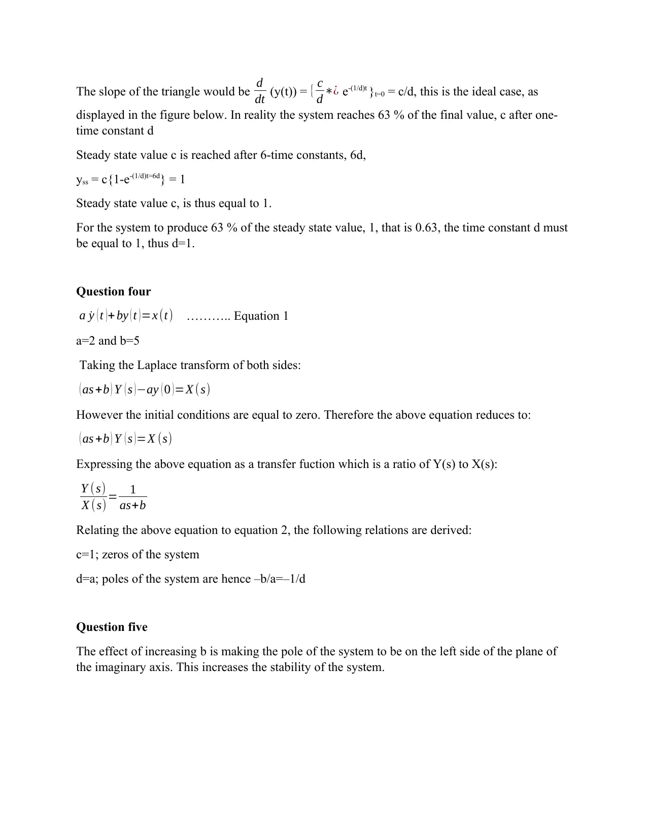
if the output had continued rising at the rate at which it started, it would reach steady state, k
after time, d. as indicated in figure 2 below.
Fig. 2
Document Page
The slope of the triangle would be d
dt (y(t)) = { c
d ¿ e-(1/d)t }t=0 = c/d, this is the ideal case, as
displayed in the figure below. In reality the system reaches 63 % of the final value, c after one-
time constant d
Steady state value c is reached after 6-time constants, 6d,
yss = c{1-e-(1/d)t=6d} = 1
Steady state value c, is thus equal to 1.
For the system to produce 63 % of the steady state value, 1, that is 0.63, the time constant d must
be equal to 1, thus d=1.
Question four
a ˙y ( t ) + by ( t ) =x (t) ……….. Equation 1
a=2 and b=5
Taking the Laplace transform of both sides:
( as +b ) Y ( s ) ay ( 0 ) =X (s)
However the initial conditions are equal to zero. Therefore the above equation reduces to:
( as +b ) Y ( s ) =X (s)
Expressing the above equation as a transfer fuction which is a ratio of Y(s) to X(s):
Y ( s)
X (s) = 1
as+b
Relating the above equation to equation 2, the following relations are derived:
c=1; zeros of the system
d=a; poles of the system are hence –b/a=–1/d
Question five
The effect of increasing b is making the pole of the system to be on the left side of the plane of
the imaginary axis. This increases the stability of the system.

Secure Best Marks with AI Grader

Need help grading? Try our AI Grader for instant feedback on your assignments.
Document Page
REFERENCES
Dorf, R.C. and Bishop, R.H., Modern control systems. 12th ed. New York: Pearson, 2011.
Levine, W.S., ed. The Control Handbook (three volume set). 2nd ed. New York: CRC press,
2018.
Rantzer, A., 2015. Scalable control of positive systems. European Journal of Control, 24, pp.72-
80.
Rossiter, J.A., Model-based predictive control: a practical approach. 2nd ed. New York: CRC
press, 2017
1 out of 5
circle_padding
hide_on_mobile
zoom_out_icon
[object Object]

Your All-in-One AI-Powered Toolkit for Academic Success.

Available 24*7 on WhatsApp / Email

[object Object]