This software design document provides an overview of a peer mentoring system, including its purpose, structure, and technology used. It also includes conceptual models, design view points, and a traceability matrix.
Contribute Materials
Your contribution can guide someone’s learning journey. Share your
documents today.
Software Design Document 1
Secure Best Marks with AI Grader
Need help grading? Try our AI Grader for instant feedback on your assignments.
1. EXECUTIVE SUMMARY It has summarised that project is based on the peer mentoring system that will help for sending emails to student, who are candidates to be participants in the program. It has been included various type of options and provide facilities to check feedback through online system. it is connected with the database that will gain necessary information about student and their results. Furthermore, it has supported the large number of student where they can easily share or check the review of mentors. The project should be addressed the various problem that will maintain the efficiency by reducing time and also save work load. 2
2. INTRODUCTION Background of project: Australian institute of higher education is the biggest ambitious that recognised as an innovator for developing a new system. So, as they were creating an effective relationship between student and providing the better services related teaching or learning. Ain is to develop an efficient system that will help for organization send email and invite for student to participant in the peer mentoring program. Purpose: The primary aim of project is to build the system which is automatically send email to the student, who are participants in the mentorship program (Acharjee, 2019). The system is helping for mentees and mentor to check online feedback. The project become useful for creating effective work environment that will achieve business goals and objectives. Structure: The overall structure can be represented through work break down in detailed manner. It should be categorised the different task where every participants role for development an efficient peer mentoring system. It mainly includes developer, tester, programmer for gathering necessary information’s. 3. Conceptual Model Technology used: There are different type of computer programming language used for system design and development. It mainly involves HTML, CSS, JavaScript and Node.js Overviewof system: The Peer Mentoring system will be performed the different functionality. 1.Student can use system to choose option of different mentee categories and finding the review of particular mentor (Panda, Acharya and Mohapatra, 2019). 2.The system should be contained the large number of datasheets within standard format. It become easier for student to access details through system. 3.Student can use login id, password to import the database file in the system. 4
Paraphrase This Document
Need a fresh take? Get an instant paraphrase of this document with our AI Paraphraser
Architectural Pattern: Figure1Architectural design/Block diagram The diagram is representing the overall functionality of peer mentoring system where how overall system works in proper manner. It can be categorized into two types: mentor-tutor and mentor-coach. They are different roles for participants to establish the coordination with students. 4. Design View Points Logical Class Diagram Figure2Class Diagram 5
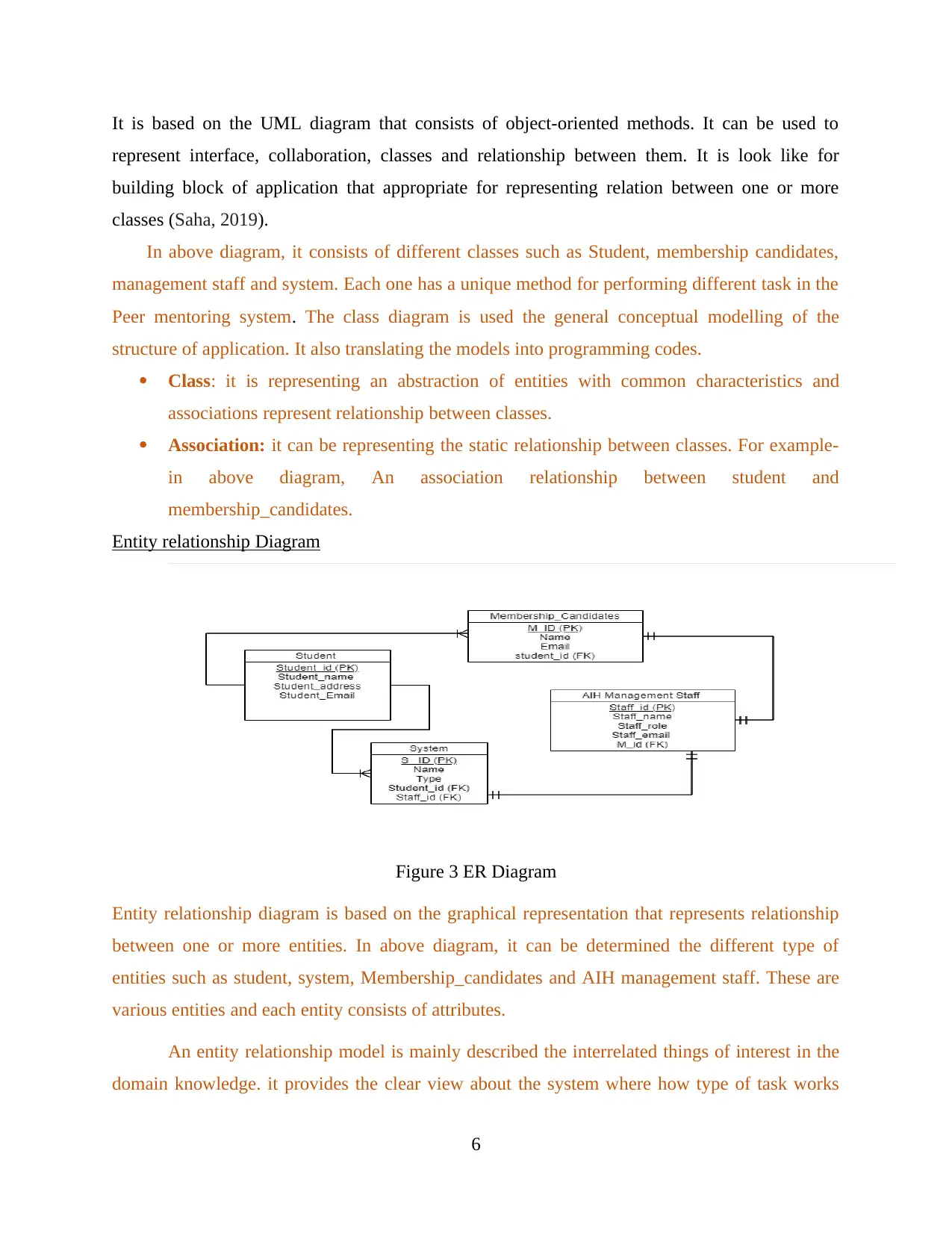
It is based on the UML diagram that consists of object-oriented methods. It can be used to represent interface, collaboration, classes and relationship between them. It is look like for building block of application that appropriate for representing relation between one or more classes (Saha, 2019). In above diagram, it consists of different classes such as Student, membership candidates, management staff and system. Each one has a unique method for performing different task in the Peer mentoring system.The class diagram is used the general conceptual modelling of the structure of application. It also translating the models into programming codes. Class: it is representing an abstraction of entities with common characteristics and associations represent relationship between classes. Association:it can be representing the static relationship between classes. For example- inabovediagram,Anassociationrelationshipbetweenstudentand membership_candidates. Entity relationship Diagram Figure3ER Diagram Entity relationship diagram is based on the graphical representation that represents relationship between one or more entities. In above diagram, it can be determined the different type of entities such as student, system, Membership_candidates and AIH management staff. These are various entities and each entity consists of attributes. An entity relationship model is mainly described the interrelated things of interest in the domain knowledge. it provides the clear view about the system where how type of task works 6
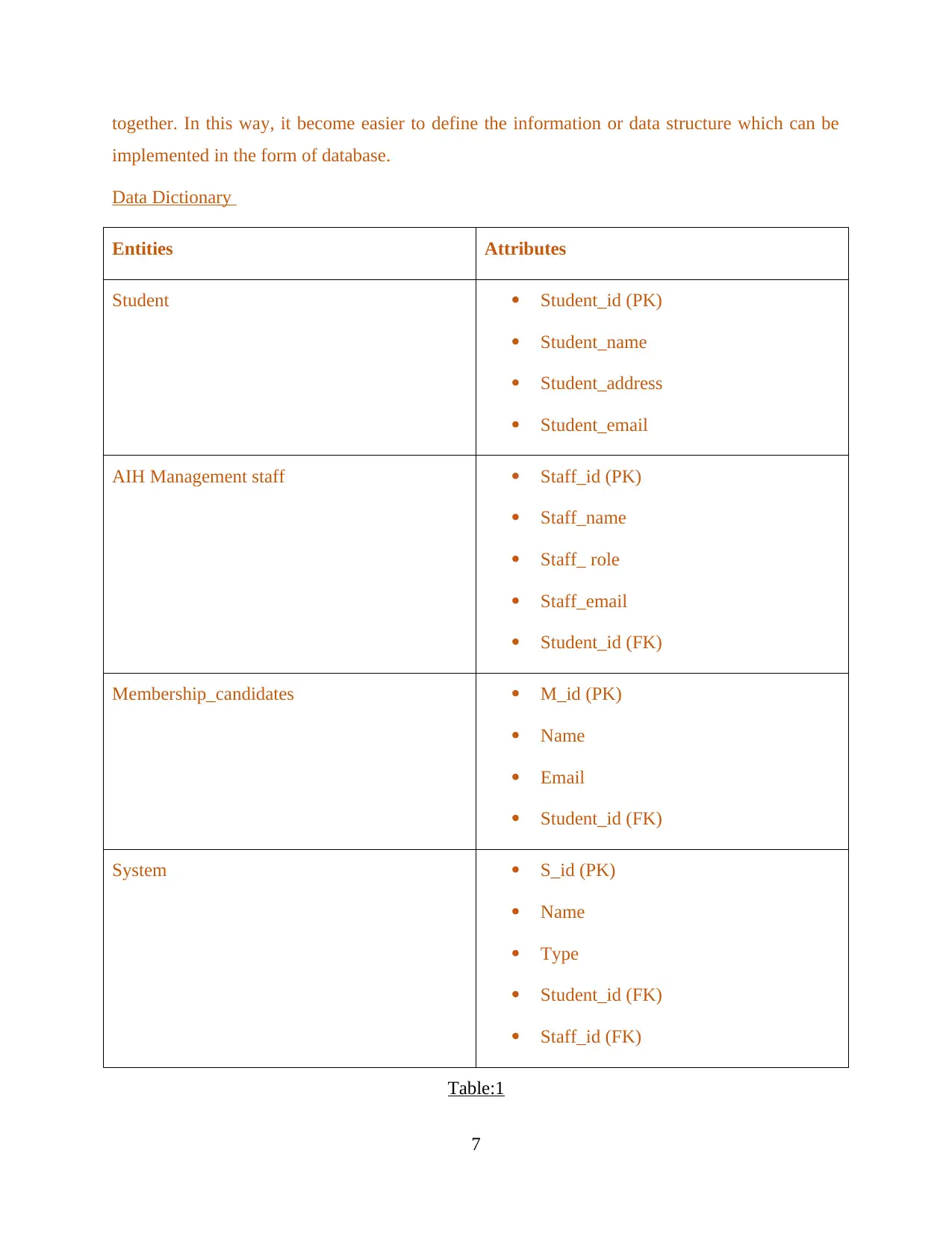
together. In this way, it become easier to define the information or data structure which can be implemented in the form of database. Data Dictionary EntitiesAttributes StudentStudent_id (PK) Student_name Student_address Student_email AIH Management staffStaff_id (PK) Staff_name Staff_ role Staff_email Student_id (FK) Membership_candidatesM_id (PK) Name Email Student_id (FK) SystemS_id (PK) Name Type Student_id (FK) Staff_id (FK) Table:1 7
Secure Best Marks with AI Grader
Need help grading? Try our AI Grader for instant feedback on your assignments.
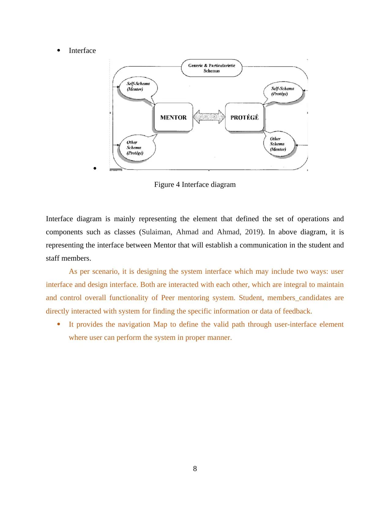
Interface Figure4Interface diagram Interface diagram is mainly representing the element that defined the set of operations and components such as classes (Sulaiman, Ahmad and Ahmad, 2019). In above diagram, it is representing the interface between Mentor that will establish a communication in the student and staff members. As per scenario, it is designing the system interface which may include two ways: user interface and design interface. Both are interacted with each other, which are integral to maintain and control overall functionality of Peer mentoring system. Student, members_candidates are directly interacted with system for finding the specific information or data of feedback. It provides the navigation Map to define the valid path through user-interface element where user can perform the system in proper manner. 8
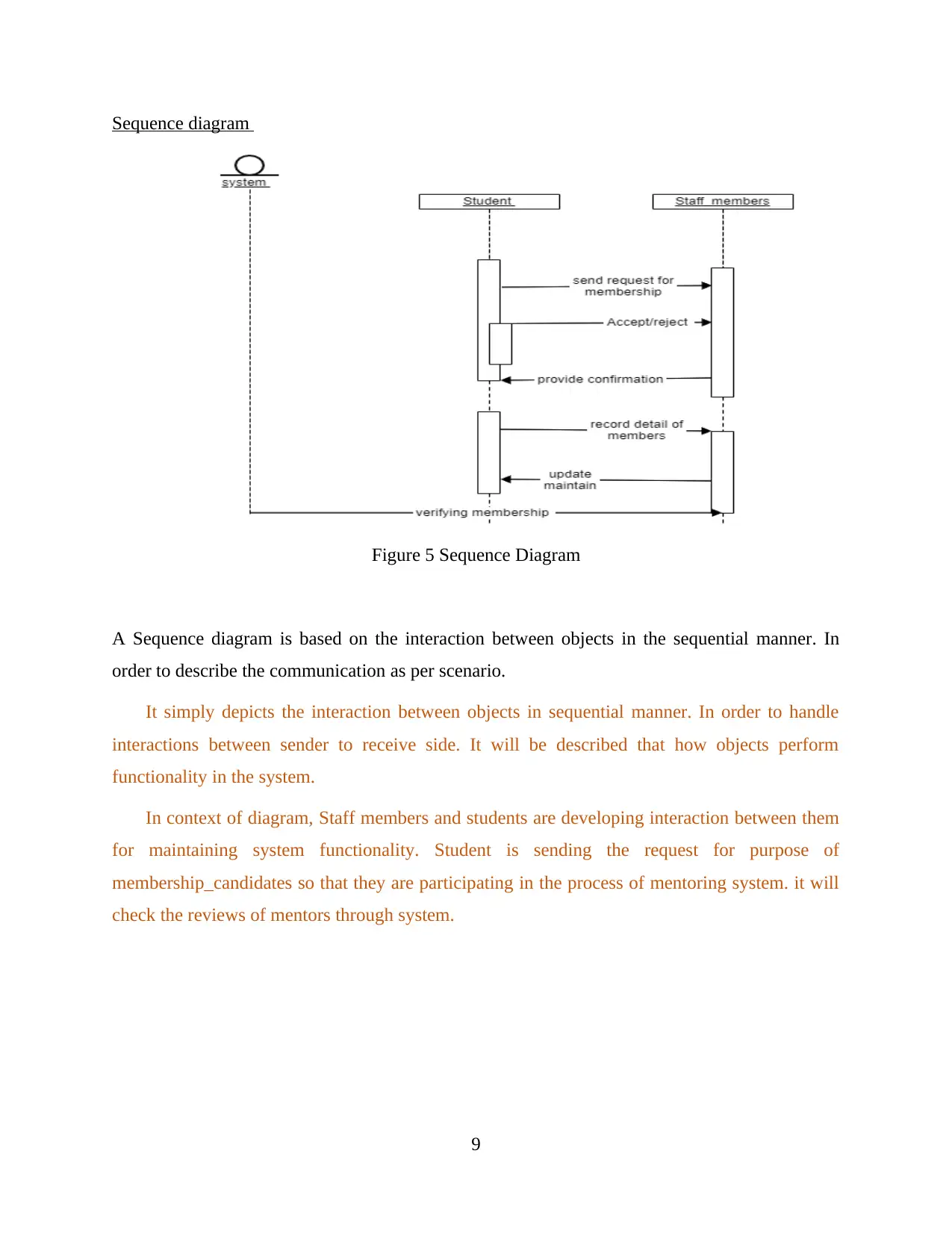
Sequence diagram Figure5Sequence Diagram A Sequence diagram is based on the interaction between objects in the sequential manner. In order to describe the communication as per scenario. It simply depicts the interaction between objects in sequential manner. In order to handle interactions between sender to receive side. It will be described that how objects perform functionality in the system. In context of diagram, Staff members and students are developing interaction between them formaintainingsystemfunctionality.Studentissendingtherequestforpurposeof membership_candidates so that they are participating in the process of mentoring system. it will check the reviews of mentors through system. 9
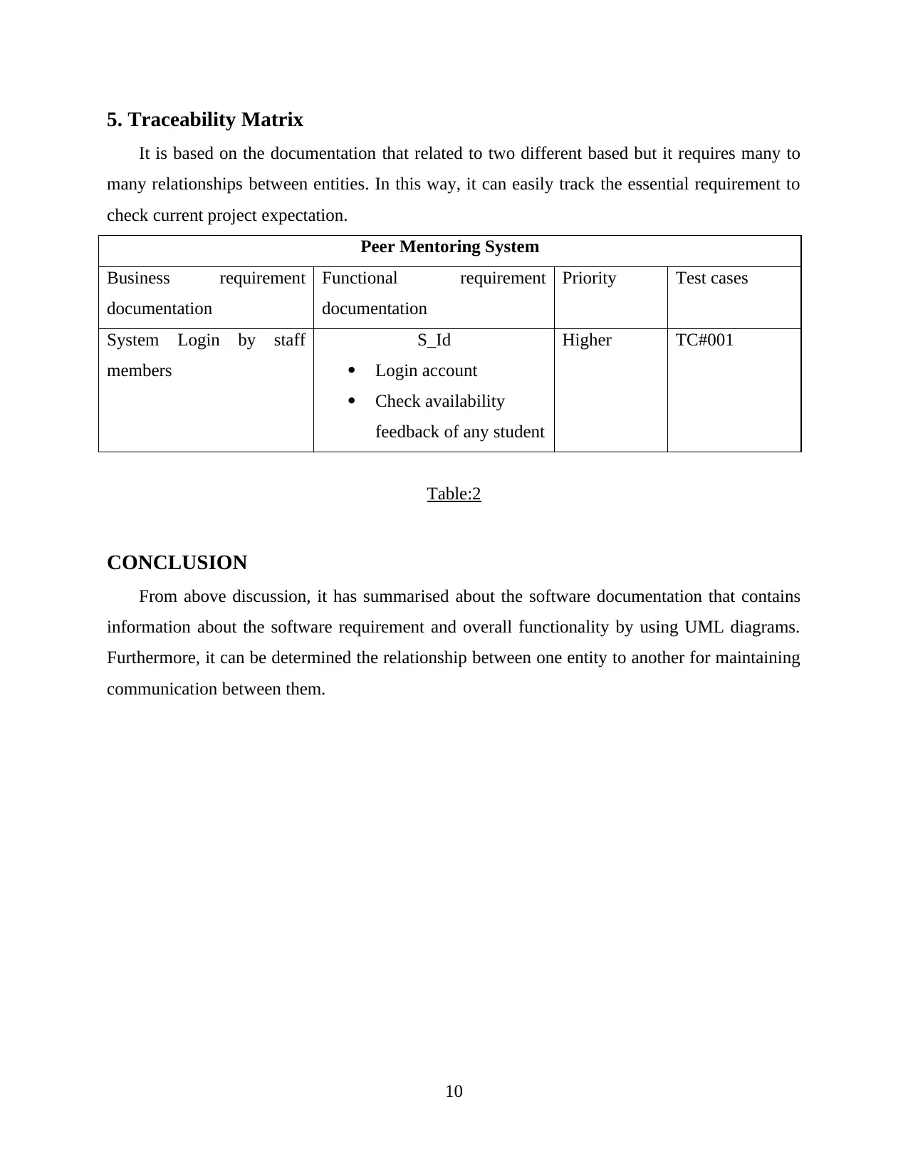
5. Traceability Matrix It is based on the documentation that related to two different based but it requires many to many relationships between entities. In this way, it can easily track the essential requirement to check current project expectation. Peer Mentoring System Businessrequirement documentation Functionalrequirement documentation PriorityTest cases SystemLoginbystaff members S_Id Login account Check availability feedback of any student HigherTC#001 Table:2 CONCLUSION From above discussion, it has summarised about the software documentation that contains information about the software requirement and overall functionality by using UML diagrams. Furthermore, it can be determined the relationship between one entity to another for maintaining communication between them. 10
Paraphrase This Document
Need a fresh take? Get an instant paraphrase of this document with our AI Paraphraser
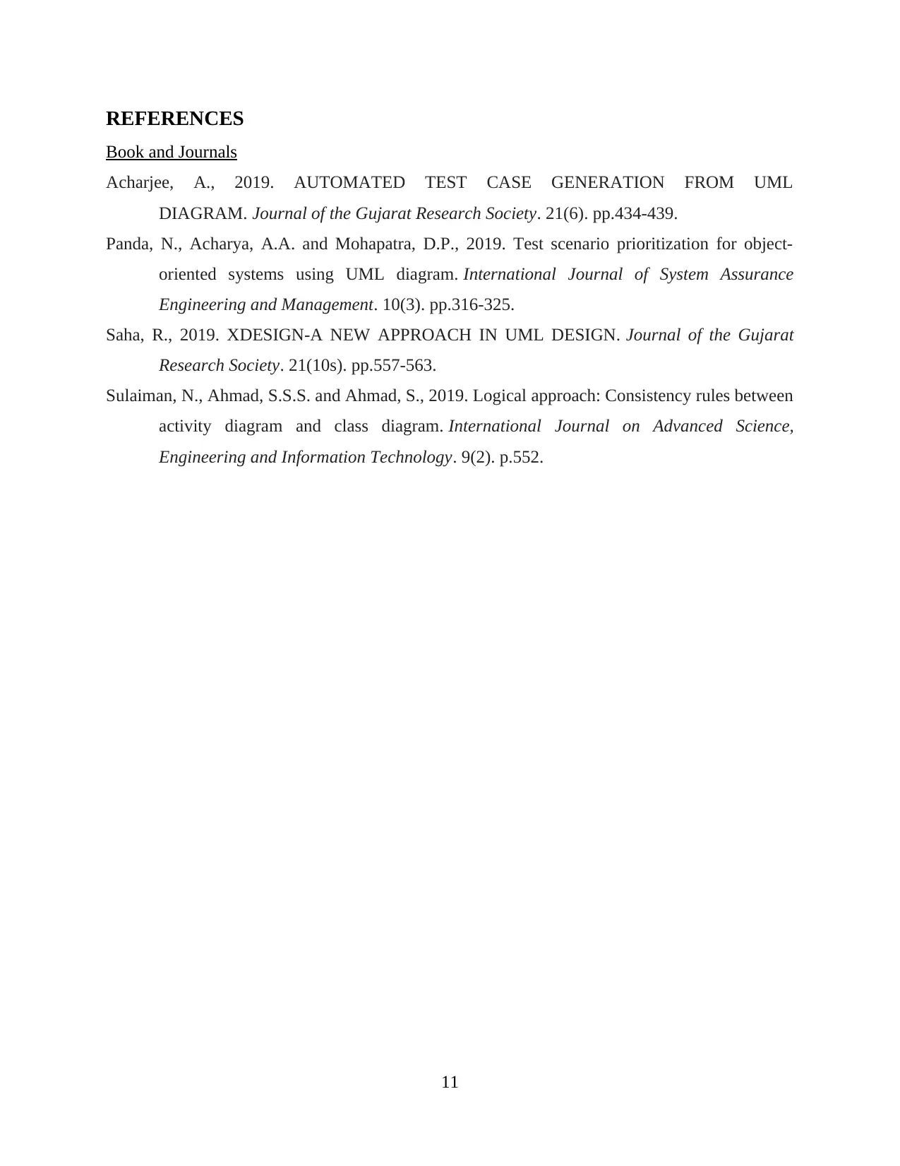
REFERENCES Book and Journals Acharjee,A.,2019.AUTOMATEDTESTCASEGENERATIONFROMUML DIAGRAM.Journal of the Gujarat Research Society. 21(6). pp.434-439. Panda, N., Acharya, A.A. and Mohapatra, D.P., 2019. Test scenario prioritization for object- orientedsystemsusingUMLdiagram.InternationalJournalofSystemAssurance Engineering and Management. 10(3). pp.316-325. Saha, R., 2019. XDESIGN-A NEW APPROACH IN UML DESIGN.Journal of the Gujarat Research Society.21(10s). pp.557-563. Sulaiman, N., Ahmad, S.S.S. and Ahmad, S., 2019. Logical approach: Consistency rules between activitydiagramandclassdiagram.InternationalJournalonAdvancedScience, Engineering and Information Technology.9(2). p.552. 11