The software design can be considered as the procedure for converting the requirements of the user into appropriate forms that assists the programmer in coding the software and developing the proposed system.
Contribute Materials
Your contribution can guide someone’s learning journey. Share your
documents today.
Running head:SOFTWARE DESIGN SPECIFICATION Software Design Specification Name of the Student Name of the University Author’s note:
Secure Best Marks with AI Grader
Need help grading? Try our AI Grader for instant feedback on your assignments.
1SOFTWARE DESIGN SPECIFICATION Table of Contents Introduction:....................................................................................................................................2 Purpose of SDS:...........................................................................................................................2 Scope:..........................................................................................................................................3 Objective:.....................................................................................................................................3 User Interfaces:................................................................................................................................3 UML Design Diagrams:..................................................................................................................4 Class Diagram:.............................................................................................................................4 Acceptance Test Cases:...............................................................................................................4 System Level State Chart Diagram:............................................................................................5 State Chart Diagram for the Main Controller Class:...................................................................5 Class protocol Test Cases:...........................................................................................................6 Implementation Constraints:............................................................................................................6 Definitions:......................................................................................................................................6 Conclusion:......................................................................................................................................7 References:......................................................................................................................................8
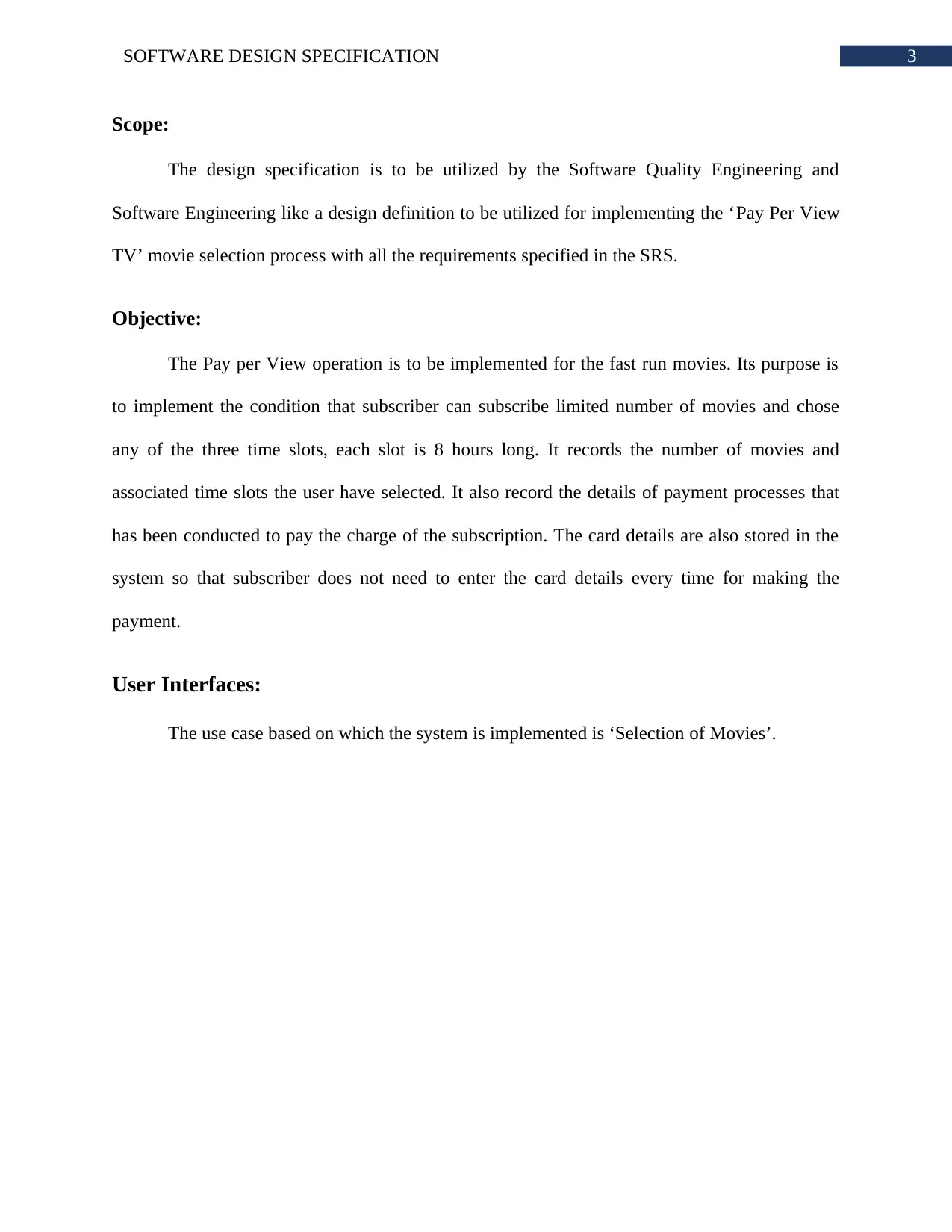
2SOFTWARE DESIGN SPECIFICATION Introduction: The software design can be considered as the procedure for converting the requirements of the user into appropriate forms that assists the programmer in coding the software and developing the proposed system. The SRS or software requirement specification document is used for documenting the analysis of the software by the analyst. The data presented in the SRS document are used for creating the design of the system. The design related information of the system is stored in the SDS document. The application design is considered as the initial phase for converting the concentration of the project from the concern domain to the solution domain. The document holds the information of system design and various testing cases. The system designs will be based on the case study ofPay Per View TV. A user interface will be given based on the use case of selecting the movies for broadcasting in the TV. There will be few conditions for selecting the movies which will be also mentioned in the interface through hints. Purpose of SDS: The document will be used for defining the design of thePay Per View TV’s movie broadcast selection process. This document consists of particular information regarding the suitable output, input, functions and classes. The document also holds the interface design to provide an idea of the navigation through out the system, the type of inputs and how the data is presented in the subscriber’s TV. It also shows the interaction among the classes to complete a process. The class diagrams and state chart diagrams will be provided within the document to provide an idea of the actual system design.
3SOFTWARE DESIGN SPECIFICATION Scope: The design specification is to be utilized by the Software Quality Engineering and Software Engineering like a design definition to be utilized for implementing the ‘Pay Per View TV’ movie selection process with all the requirements specified in the SRS. Objective: The Pay per View operation is to be implemented for the fast run movies. Its purpose is to implement the condition that subscriber can subscribe limited number of movies and chose any of the three time slots, each slot is 8 hours long. It records the number of movies and associated time slots the user have selected. It also record the details of payment processes that has been conducted to pay the charge of the subscription. The card details are also stored in the system so that subscriber does not need to enter the card details every time for making the payment. User Interfaces: The use case based on which the system is implemented is ‘Selection of Movies’.
Paraphrase This Document
Need a fresh take? Get an instant paraphrase of this document with our AI Paraphraser
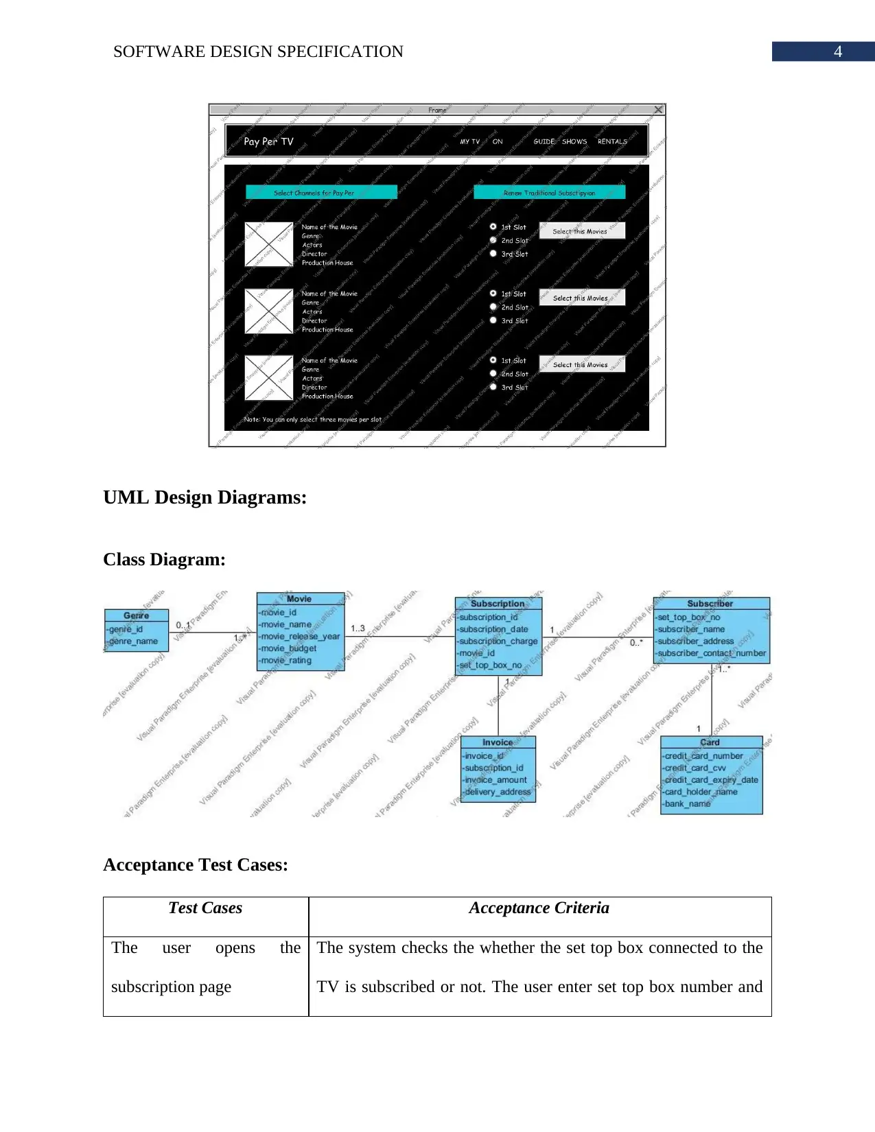
4SOFTWARE DESIGN SPECIFICATION UML Design Diagrams: Class Diagram: Acceptance Test Cases: Test CasesAcceptance Criteria Theuseropensthe subscription page The system checks the whether the set top box connected to the TV is subscribed or not. The user enter set top box number and
5SOFTWARE DESIGN SPECIFICATION system validates it. Only the authorized users are allowed to access the system Thesubscriberselects more than three movies in a time slot The system shows an alert message that no more than three movies for a time slot can be selected. The subscriber selects three or lessmovies in a time slot Thesystemauthorizestheselectionandconfirmsthe subscription. Redirect the user to payment section Theuserenterthecard details The system verify the format and length of the details. If the card details are wring, an error message is prompt on the screen and subscriber is asked to enter the details again. If the card details are right then an OTP is sent to the customer registered mobile number. Userselectsthepre- registered card The system sends an OTP is sent to the customer registered mobile number directly The user enter the OTPThe system verify the OTP and initiate the paymentdeduction from account. If account has sufficient balance then subscription is activated otherwise the subscription request is cancelled. In case of cancellation of subscription, the system gets a proper error message in the screen.
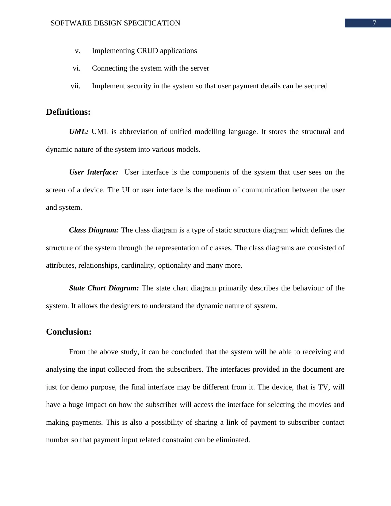
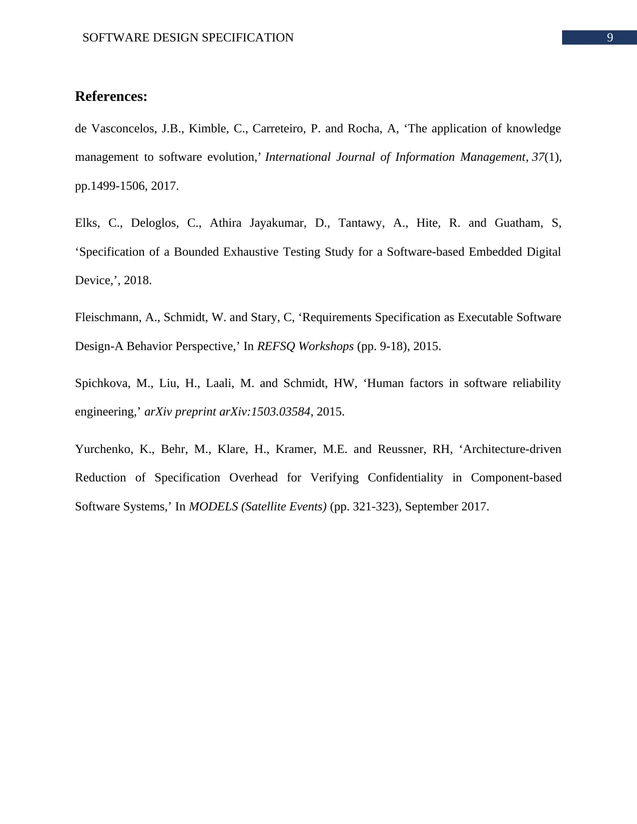
6SOFTWARE DESIGN SPECIFICATION System Level State Chart Diagram: State Chart Diagram for the Main Controller Class: Class protocol Test Cases: Implementation Constraints: The primary implementation constraints are as following. i.Integrating the interface into the set top box ii.Choosing the interaction medium between the subscriber and system iii.Implementing the user interface so that subscriber can easily interact with the system iv.Making the system available 24*7
Secure Best Marks with AI Grader
Need help grading? Try our AI Grader for instant feedback on your assignments.
7SOFTWARE DESIGN SPECIFICATION v.Implementing CRUD applications vi.Connecting the system with the server vii.Implement security in the system so that user payment details can be secured Definitions: UML:UML is abbreviation of unified modelling language. It stores the structural and dynamic nature of the system into various models. User Interface:User interface is the components of the system that user sees on the screen of a device. The UI or user interface is the medium of communication between the user and system. Class Diagram:The class diagram is a type of static structure diagram which defines the structure of the system through the representation of classes. The class diagrams are consisted of attributes, relationships, cardinality, optionality and many more. State Chart Diagram:The state chart diagram primarily describes the behaviour of the system. It allows the designers to understand the dynamic nature of system. Conclusion: From the above study, it can be concluded that the system will be able to receiving and analysing the input collected from the subscribers. The interfaces provided in the document are just for demo purpose, the final interface may be different from it. The device, that is TV, will have a huge impact on how the subscriber will access the interface for selecting the movies and making payments. This is also a possibility of sharing a link of payment to subscriber contact number so that payment input related constraint can be eliminated.
8SOFTWARE DESIGN SPECIFICATION
9SOFTWARE DESIGN SPECIFICATION References: de Vasconcelos, J.B., Kimble, C., Carreteiro, P. and Rocha, A, ‘The application of knowledge management to software evolution,’International Journal of Information Management,37(1), pp.1499-1506, 2017. Elks,C.,Deloglos,C.,AthiraJayakumar,D.,Tantawy,A.,Hite,R.andGuatham,S, ‘Specification of a Bounded Exhaustive Testing Study for a Software-based Embedded Digital Device,’, 2018. Fleischmann, A., Schmidt, W. and Stary, C, ‘Requirements Specification as Executable Software Design-A Behavior Perspective,’ InREFSQ Workshops(pp. 9-18), 2015. Spichkova, M., Liu, H., Laali, M. and Schmidt, HW, ‘Human factors in software reliability engineering,’arXiv preprint arXiv:1503.03584, 2015. Yurchenko, K., Behr, M., Klare, H., Kramer, M.E. and Reussner, RH, ‘Architecture-driven ReductionofSpecificationOverheadforVerifyingConfidentialityinComponent-based Software Systems,’ InMODELS (Satellite Events)(pp. 321-323), September 2017.