ProductsLogo
LogoStudy Documents
LogoAI Grader
LogoAI Answer
LogoAI Code Checker
LogoPlagiarism Checker
LogoAI Paraphraser
LogoAI Quiz
LogoAI Detector
PricingBlogAbout Us
logo

Applying Structural Principles to Residential Low-Rise Constructions

Verified

Added on  2023/06/07

|8
|789
|479
AI Summary
This article discusses the process of applying structural principles to residential low-rise constructions. It covers the steps from site clearing and levelling to the finished slab, including excavation, placement of service pipes, sand bed placement, formwork setup, and concrete curing. The article emphasizes the importance of following appropriate guidelines and using qualified personnel for each step.

Contribute Materials

Your contribution can guide someone’s learning journey. Share your documents today.
Document Page
Apply Structural Principles 1
APPLY STRUCTURAL PRINCIPLES TO RESIDENTIAL LOW-RISE CONSTRUCTIONS
Name
Course
Professor
University
City/state
Date

Secure Best Marks with AI Grader

Need help grading? Try our AI Grader for instant feedback on your assignments.
Document Page
Apply Structural Principles 2
Apply Structural Principles to Residential Low-Rise Constructions
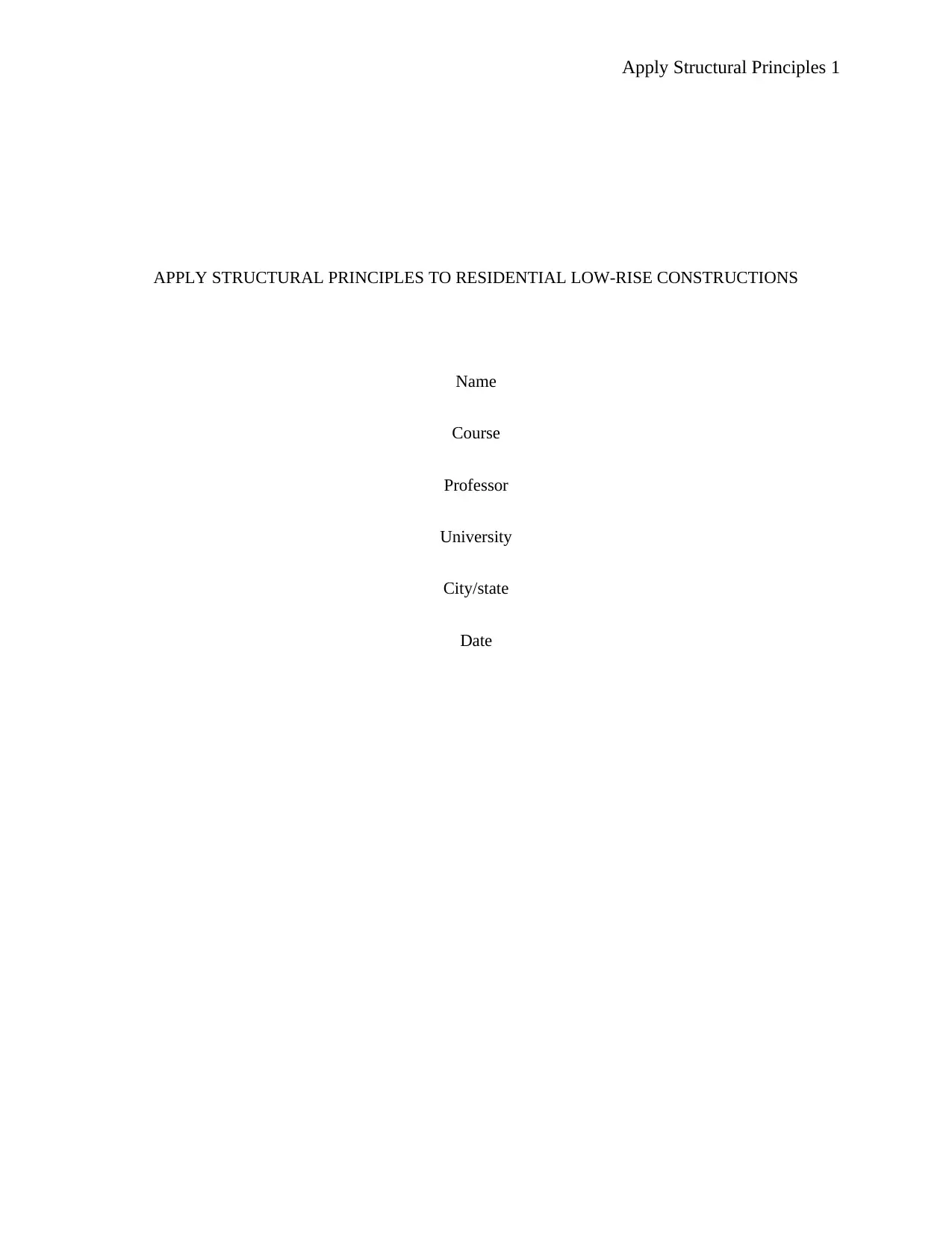
1. A vacant building site
Figure 1: Vacant building site
The vacant building site is as shown in Figure 1 above. The site is not level, has minimal vegetation (only
grass) and does not have any existing buildings to be demolished.
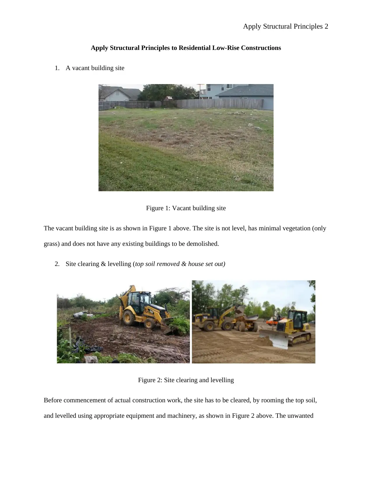
2. Site clearing & levelling (top soil removed & house set out)
Figure 2: Site clearing and levelling
Before commencement of actual construction work, the site has to be cleared, by rooming the top soil,
and levelled using appropriate equipment and machinery, as shown in Figure 2 above. The unwanted
Document Page
Apply Structural Principles 3
materials are also transported and removed from the site to allow more space for safe construction
activities.
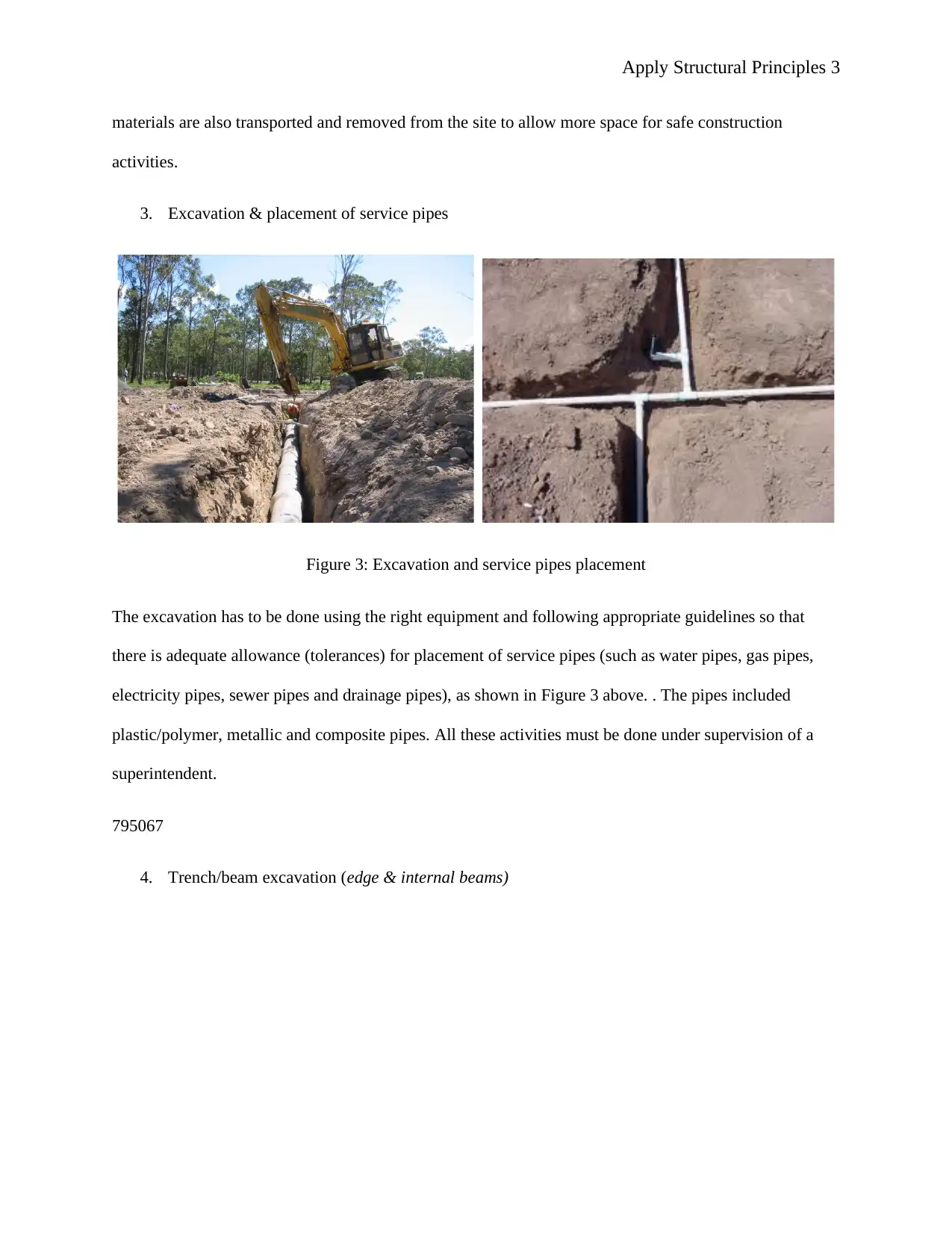
3. Excavation & placement of service pipes
Figure 3: Excavation and service pipes placement
The excavation has to be done using the right equipment and following appropriate guidelines so that
there is adequate allowance (tolerances) for placement of service pipes (such as water pipes, gas pipes,
electricity pipes, sewer pipes and drainage pipes), as shown in Figure 3 above. . The pipes included
plastic/polymer, metallic and composite pipes. All these activities must be done under supervision of a
superintendent.
795067
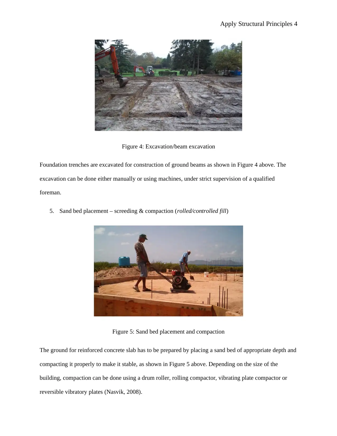
4. Trench/beam excavation (edge & internal beams)
Document Page
Apply Structural Principles 4
Figure 4: Excavation/beam excavation
Foundation trenches are excavated for construction of ground beams as shown in Figure 4 above. The
excavation can be done either manually or using machines, under strict supervision of a qualified
foreman.
5. Sand bed placement – screeding & compaction (rolled/controlled fill)
Figure 5: Sand bed placement and compaction
The ground for reinforced concrete slab has to be prepared by placing a sand bed of appropriate depth and
compacting it properly to make it stable, as shown in Figure 5 above. Depending on the size of the
building, compaction can be done using a drum roller, rolling compactor, vibrating plate compactor or
reversible vibratory plates (Nasvik, 2008).

Paraphrase This Document

Need a fresh take? Get an instant paraphrase of this document with our AI Paraphraser
Document Page
Apply Structural Principles 5
6. Formwork setup and laying of vapour barrier/damp-proof membrane
Figure 6: Formwork setup and damp-proof membrane laying
The damp-proof membrane has to be laid on a smooth horizontal sand bed just before laying the concrete
floor and should span the entire floor area, as shown in Figure 6 above. Any joins of the damp-proof
membrane have to be properly lapped and taped using water-resistant adhesive tape.
7. Position of all steel reinforcement service penetrations, termite measures used
Figure 7: Steel reinforcement positioned on the damp-proof membrane
Document Page
Apply Structural Principles 6
After laying the damp-proof membrane, steel reinforcement is installed on top of it before floor concrete
can be poured onto it, as shown in Figure 7 above.
8. The concrete pour (truck deliver & placement)
Figure 8: Concrete pour
Truck delivered concrete of required strength is poured onto the prepared steel-reinforced floor, as shown
in Figure 8 above.
9. Screeding the concrete & trowelling of surface (finishing & levelling)
Document Page
Apply Structural Principles 7
Figure 9: Concrete screeding and levelling
Once the concrete is laid, a wet screed is added on top of it and levelled to have a smooth and horizontal
floor. This has to be done using appropriate equipment and by a qualified concrete layer.
10. Concrete curing (still within formwork)
Figure 10: Concrete curing
The concrete has to be cured for seven consecutive days by ponding or flooding it with water, as shown in
Figure 10 above (Mishra, 2018). This helps the concrete to attain maximum strength within 28 days.
11. A finished slab (with formwork removed)
Figure 11: Finished slab

Secure Best Marks with AI Grader

Need help grading? Try our AI Grader for instant feedback on your assignments.
Document Page
Apply Structural Principles 8
The finished concrete floor slab should be smooth, level and aesthetically-pleasing, as shown in Figure 11
above.
References
Mishra, G., 2018. Concrete Curing Time and Duration - Right Time to Cure Concrete. [Online]
Available at: https://theconstructor.org/concrete/concrete-curing-time-duration/11119/
[Accessed 5 September 2018].
Nasvik, J., 2008. Site Preparation: Making a Proper Bed for Concrete. [Online]
Available at: https://www.concreteconstruction.net/how-to/site-prep/site-preparation-making-a-
proper-bed-for-concrete_o
[Accessed 4 September 2018].
1 out of 8
[object Object]

Your All-in-One AI-Powered Toolkit for Academic Success.

Available 24*7 on WhatsApp / Email

[object Object]