Design and Testing of Three-Phase Step-Down Transformers
VerifiedAdded on 2023/06/11
|8
|1416
|357
AI Summary
This article discusses the advantages of using three-phase transformers, their design and testing process, and the benefits of delta and star connections. It also includes test results for different transformer configurations.
Contribute Materials
Your contribution can guide someone’s learning journey. Share your
documents today.

NAME OF THE STUDENT
NAME OF THE PROFESSOR
CITY/STATE
DAY/MONTH/YEAR
NAME OF THE PROFESSOR
CITY/STATE
DAY/MONTH/YEAR
Secure Best Marks with AI Grader
Need help grading? Try our AI Grader for instant feedback on your assignments.
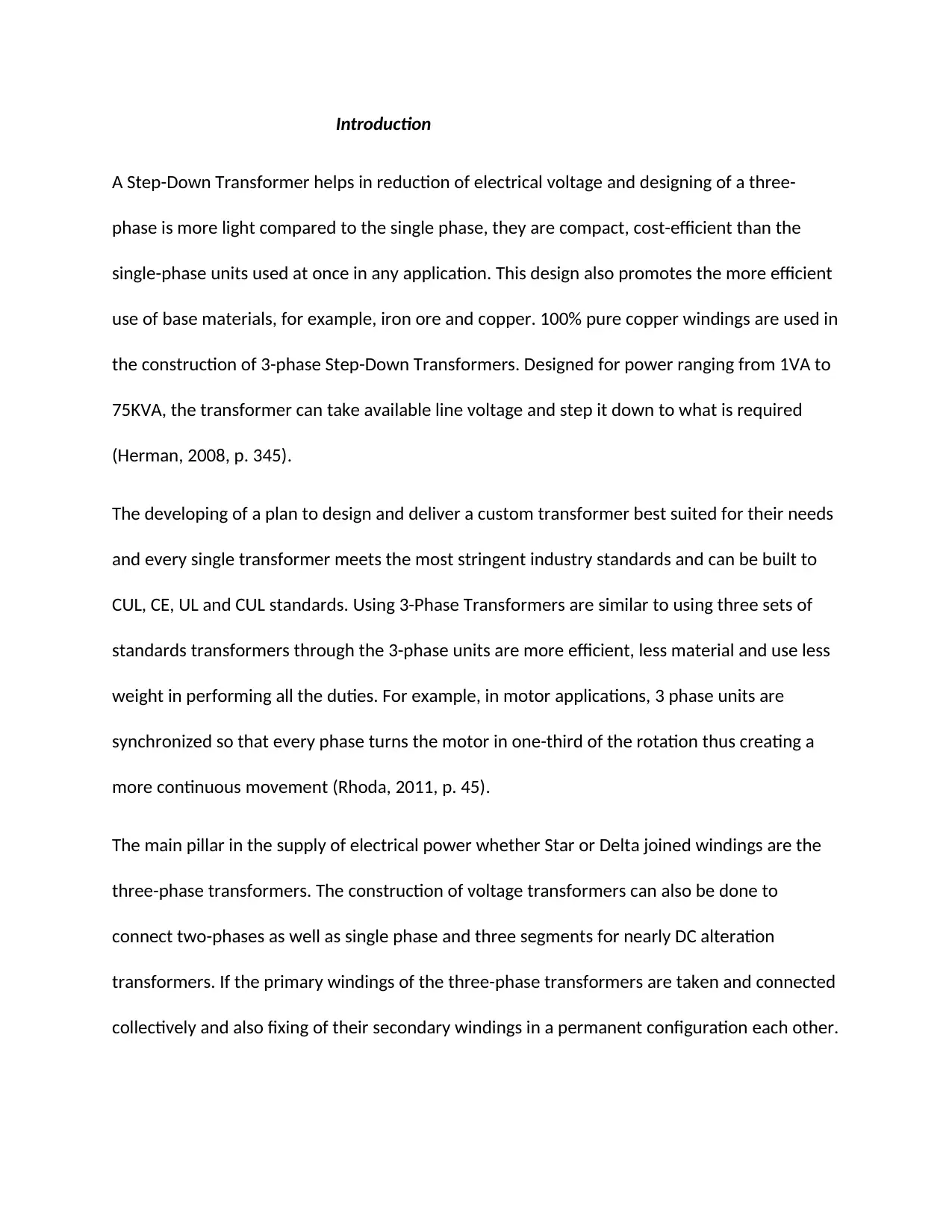
Introduction
A Step-Down Transformer helps in reduction of electrical voltage and designing of a three-
phase is more light compared to the single phase, they are compact, cost-efficient than the
single-phase units used at once in any application. This design also promotes the more efficient
use of base materials, for example, iron ore and copper. 100% pure copper windings are used in
the construction of 3-phase Step-Down Transformers. Designed for power ranging from 1VA to
75KVA, the transformer can take available line voltage and step it down to what is required
(Herman, 2008, p. 345).
The developing of a plan to design and deliver a custom transformer best suited for their needs
and every single transformer meets the most stringent industry standards and can be built to
CUL, CE, UL and CUL standards. Using 3-Phase Transformers are similar to using three sets of
standards transformers through the 3-phase units are more efficient, less material and use less
weight in performing all the duties. For example, in motor applications, 3 phase units are
synchronized so that every phase turns the motor in one-third of the rotation thus creating a
more continuous movement (Rhoda, 2011, p. 45).
The main pillar in the supply of electrical power whether Star or Delta joined windings are the
three-phase transformers. The construction of voltage transformers can also be done to
connect two-phases as well as single phase and three segments for nearly DC alteration
transformers. If the primary windings of the three-phase transformers are taken and connected
collectively and also fixing of their secondary windings in a permanent configuration each other.
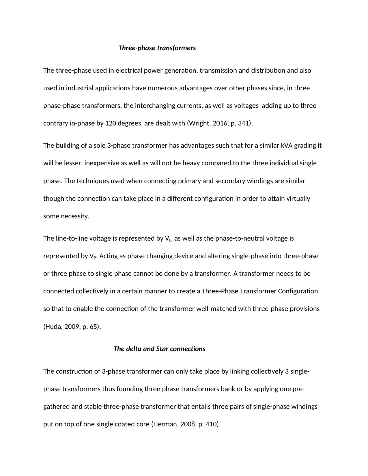
Three-phase transformers
The three-phase used in electrical power generation, transmission and distribution and also
used in industrial applications have numerous advantages over other phases since, in three
phase-phase transformers, the interchanging currents, as well as voltages adding up to three
contrary in-phase by 120 degrees, are dealt with (Wright, 2016, p. 341).
The building of a sole 3-phase transformer has advantages such that for a similar kVA grading it
will be lesser, inexpensive as well as will not be heavy compared to the three individual single
phase. The techniques used when connecting primary and secondary windings are similar
though the connection can take place in a different configuration in order to attain virtually
some necessity.
The line-to-line voltage is represented by VL, as well as the phase-to-neutral voltage is
represented by VP. Acting as phase changing device and altering single-phase into three-phase
or three phase to single phase cannot be done by a transformer. A transformer needs to be
connected collectively in a certain manner to create a Three-Phase Transformer Configuration
so that to enable the connection of the transformer well-matched with three-phase provisions
(Huda, 2009, p. 65).
The delta and Star connections
The construction of 3-phase transformer can only take place by linking collectively 3 single-
phase transformers thus founding three phase transformers bank or by applying one pre-
gathered and stable three-phase transformer that entails three pairs of single-phase windings
put on top of one single coated core (Herman, 2008, p. 410).
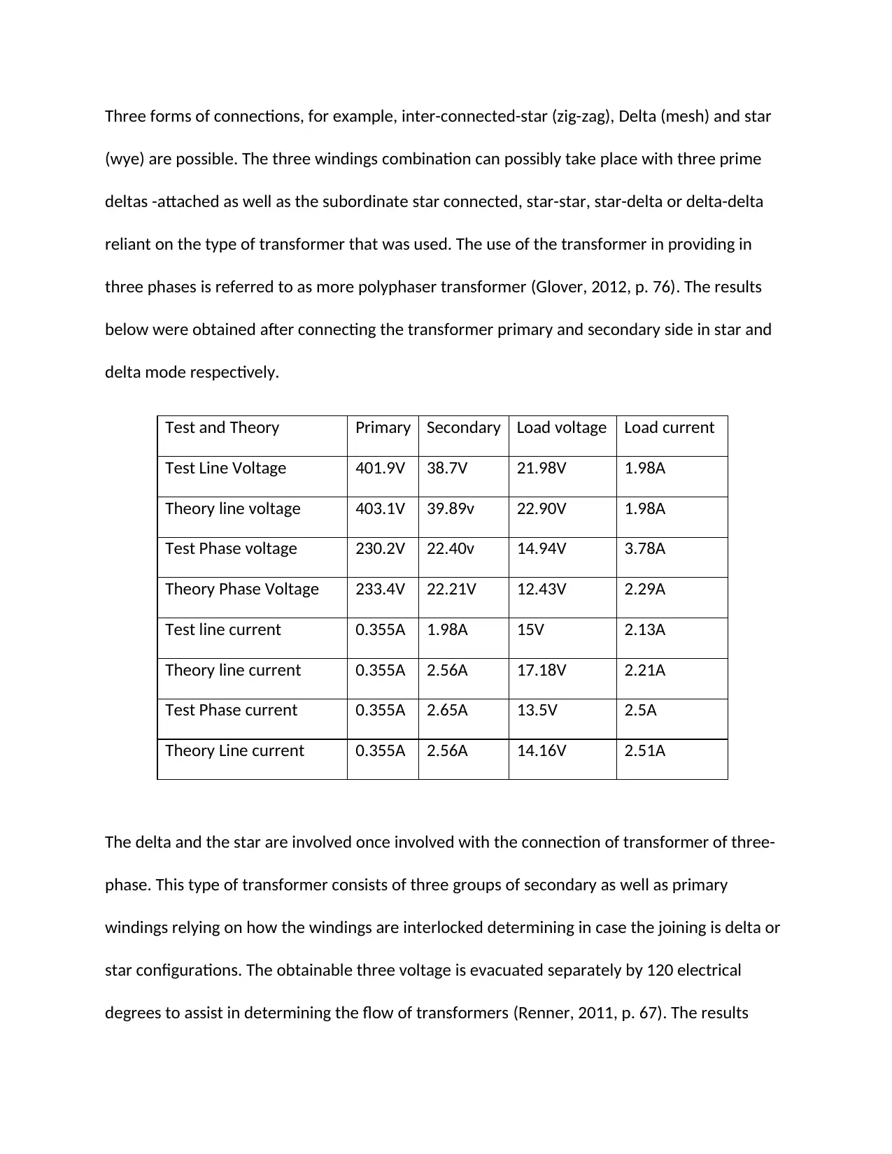
Three forms of connections, for example, inter-connected-star (zig-zag), Delta (mesh) and star
(wye) are possible. The three windings combination can possibly take place with three prime
deltas -attached as well as the subordinate star connected, star-star, star-delta or delta-delta
reliant on the type of transformer that was used. The use of the transformer in providing in
three phases is referred to as more polyphaser transformer (Glover, 2012, p. 76). The results
below were obtained after connecting the transformer primary and secondary side in star and
delta mode respectively.
Test and Theory Primary Secondary Load voltage Load current
Test Line Voltage 401.9V 38.7V 21.98V 1.98A
Theory line voltage 403.1V 39.89v 22.90V 1.98A
Test Phase voltage 230.2V 22.40v 14.94V 3.78A
Theory Phase Voltage 233.4V 22.21V 12.43V 2.29A
Test line current 0.355A 1.98A 15V 2.13A
Theory line current 0.355A 2.56A 17.18V 2.21A
Test Phase current 0.355A 2.65A 13.5V 2.5A
Theory Line current 0.355A 2.56A 14.16V 2.51A
The delta and the star are involved once involved with the connection of transformer of three-
phase. This type of transformer consists of three groups of secondary as well as primary
windings relying on how the windings are interlocked determining in case the joining is delta or
star configurations. The obtainable three voltage is evacuated separately by 120 electrical
degrees to assist in determining the flow of transformers (Renner, 2011, p. 67). The results
Secure Best Marks with AI Grader
Need help grading? Try our AI Grader for instant feedback on your assignments.
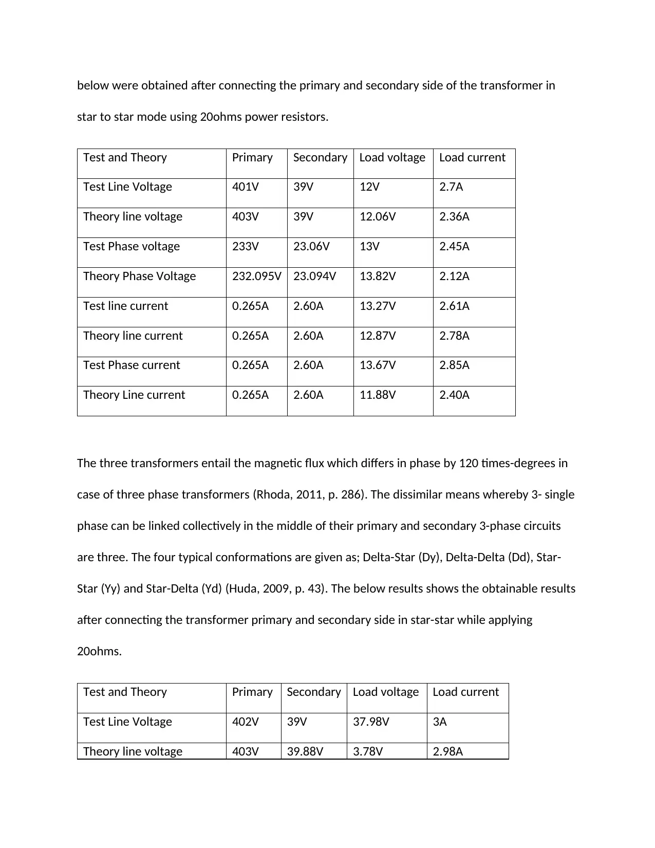
below were obtained after connecting the primary and secondary side of the transformer in
star to star mode using 20ohms power resistors.
Test and Theory Primary Secondary Load voltage Load current
Test Line Voltage 401V 39V 12V 2.7A
Theory line voltage 403V 39V 12.06V 2.36A
Test Phase voltage 233V 23.06V 13V 2.45A
Theory Phase Voltage 232.095V 23.094V 13.82V 2.12A
Test line current 0.265A 2.60A 13.27V 2.61A
Theory line current 0.265A 2.60A 12.87V 2.78A
Test Phase current 0.265A 2.60A 13.67V 2.85A
Theory Line current 0.265A 2.60A 11.88V 2.40A
The three transformers entail the magnetic flux which differs in phase by 120 times-degrees in
case of three phase transformers (Rhoda, 2011, p. 286). The dissimilar means whereby 3- single
phase can be linked collectively in the middle of their primary and secondary 3-phase circuits
are three. The four typical conformations are given as; Delta-Star (Dy), Delta-Delta (Dd), Star-
Star (Yy) and Star-Delta (Yd) (Huda, 2009, p. 43). The below results shows the obtainable results
after connecting the transformer primary and secondary side in star-star while applying
20ohms.
Test and Theory Primary Secondary Load voltage Load current
Test Line Voltage 402V 39V 37.98V 3A
Theory line voltage 403V 39.88V 3.78V 2.98A
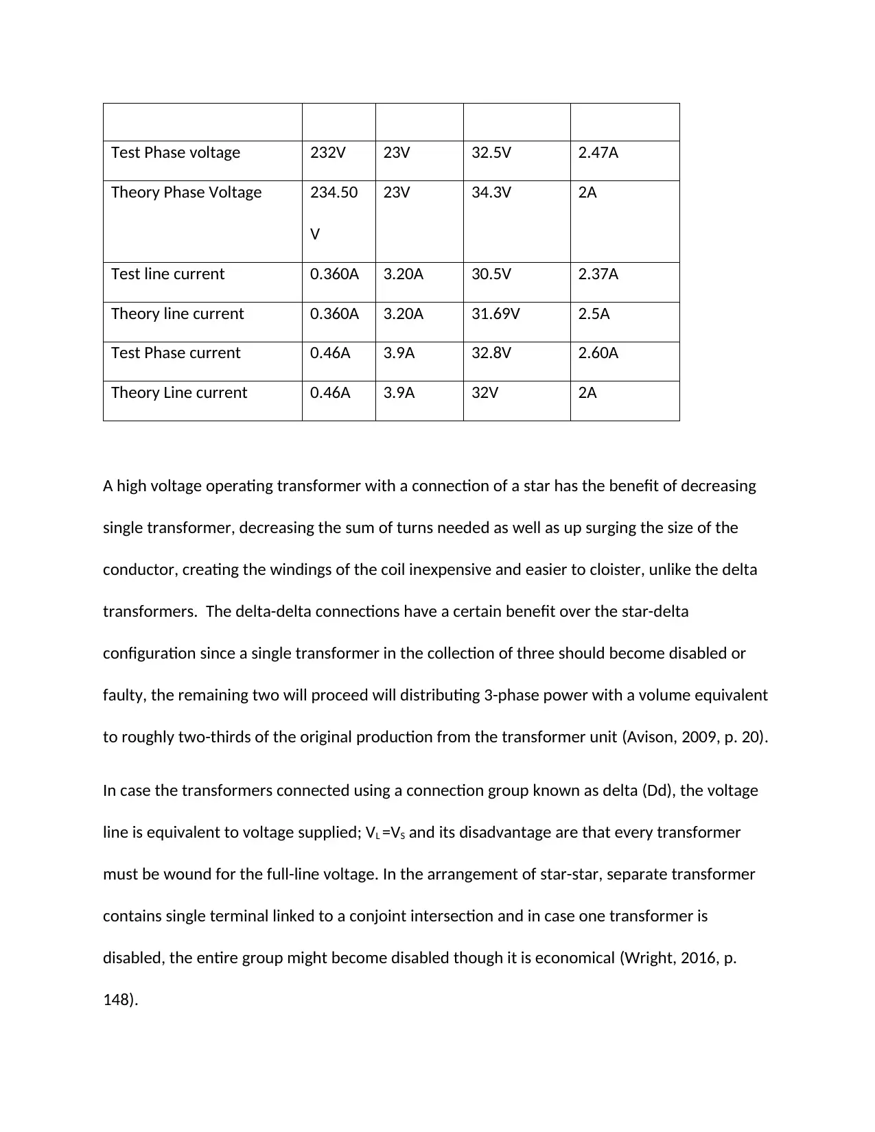
Test Phase voltage 232V 23V 32.5V 2.47A
Theory Phase Voltage 234.50
V
23V 34.3V 2A
Test line current 0.360A 3.20A 30.5V 2.37A
Theory line current 0.360A 3.20A 31.69V 2.5A
Test Phase current 0.46A 3.9A 32.8V 2.60A
Theory Line current 0.46A 3.9A 32V 2A
A high voltage operating transformer with a connection of a star has the benefit of decreasing
single transformer, decreasing the sum of turns needed as well as up surging the size of the
conductor, creating the windings of the coil inexpensive and easier to cloister, unlike the delta
transformers. The delta-delta connections have a certain benefit over the star-delta
configuration since a single transformer in the collection of three should become disabled or
faulty, the remaining two will proceed will distributing 3-phase power with a volume equivalent
to roughly two-thirds of the original production from the transformer unit (Avison, 2009, p. 20).
In case the transformers connected using a connection group known as delta (Dd), the voltage
line is equivalent to voltage supplied; VL =VS and its disadvantage are that every transformer
must be wound for the full-line voltage. In the arrangement of star-star, separate transformer
contains single terminal linked to a conjoint intersection and in case one transformer is
disabled, the entire group might become disabled though it is economical (Wright, 2016, p.
148).

References
Avison, R. (2009). The World of Physics. Chicago: Adventure Works Press.
Glover, D. (2012). Power Generation and Delivery. Boston: China Publishing Company.
Herman, S. (2008). Review of Radiologic Physics. Calgary: Pavilion Books.
Avison, R. (2009). The World of Physics. Chicago: Adventure Works Press.
Glover, D. (2012). Power Generation and Delivery. Boston: China Publishing Company.
Herman, S. (2008). Review of Radiologic Physics. Calgary: Pavilion Books.
Paraphrase This Document
Need a fresh take? Get an instant paraphrase of this document with our AI Paraphraser
Huda, W. (2009). Basic electrical power transformers. Ottawa: Andrews McMeel Publishing.
Renner, B. (2011). Hands On Water and Wastewater Equipment Maintenance. Brisbane: Baker Book
House.
Rhoda, J. (2011). Electrical Studies for Trades. Melbourne: OLMA Media Group.
Wright, C. (2016). Transmission Network Protection. Dallas: Book League of America.
Renner, B. (2011). Hands On Water and Wastewater Equipment Maintenance. Brisbane: Baker Book
House.
Rhoda, J. (2011). Electrical Studies for Trades. Melbourne: OLMA Media Group.
Wright, C. (2016). Transmission Network Protection. Dallas: Book League of America.
1 out of 8
Related Documents
Your All-in-One AI-Powered Toolkit for Academic Success.
+13062052269
info@desklib.com
Available 24*7 on WhatsApp / Email
![[object Object]](/_next/static/media/star-bottom.7253800d.svg)
Unlock your academic potential
© 2024 | Zucol Services PVT LTD | All rights reserved.


