Circuit Analysis I Lab: Function Generator and Oscilloscope Experiment
VerifiedAdded on 2021/10/01
|9
|906
|167
Practical Assignment
AI Summary
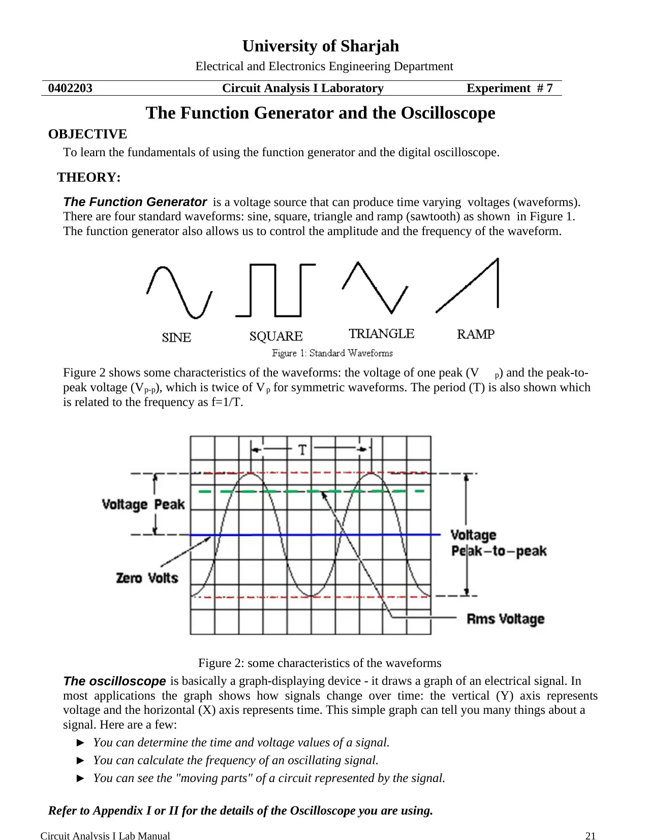
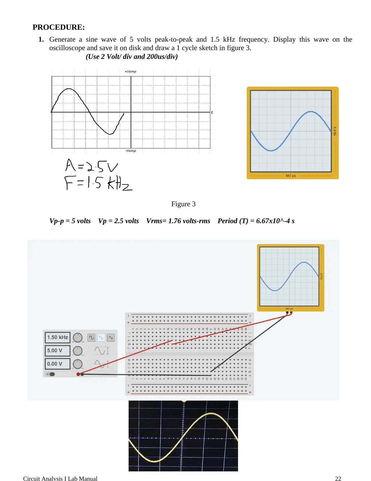
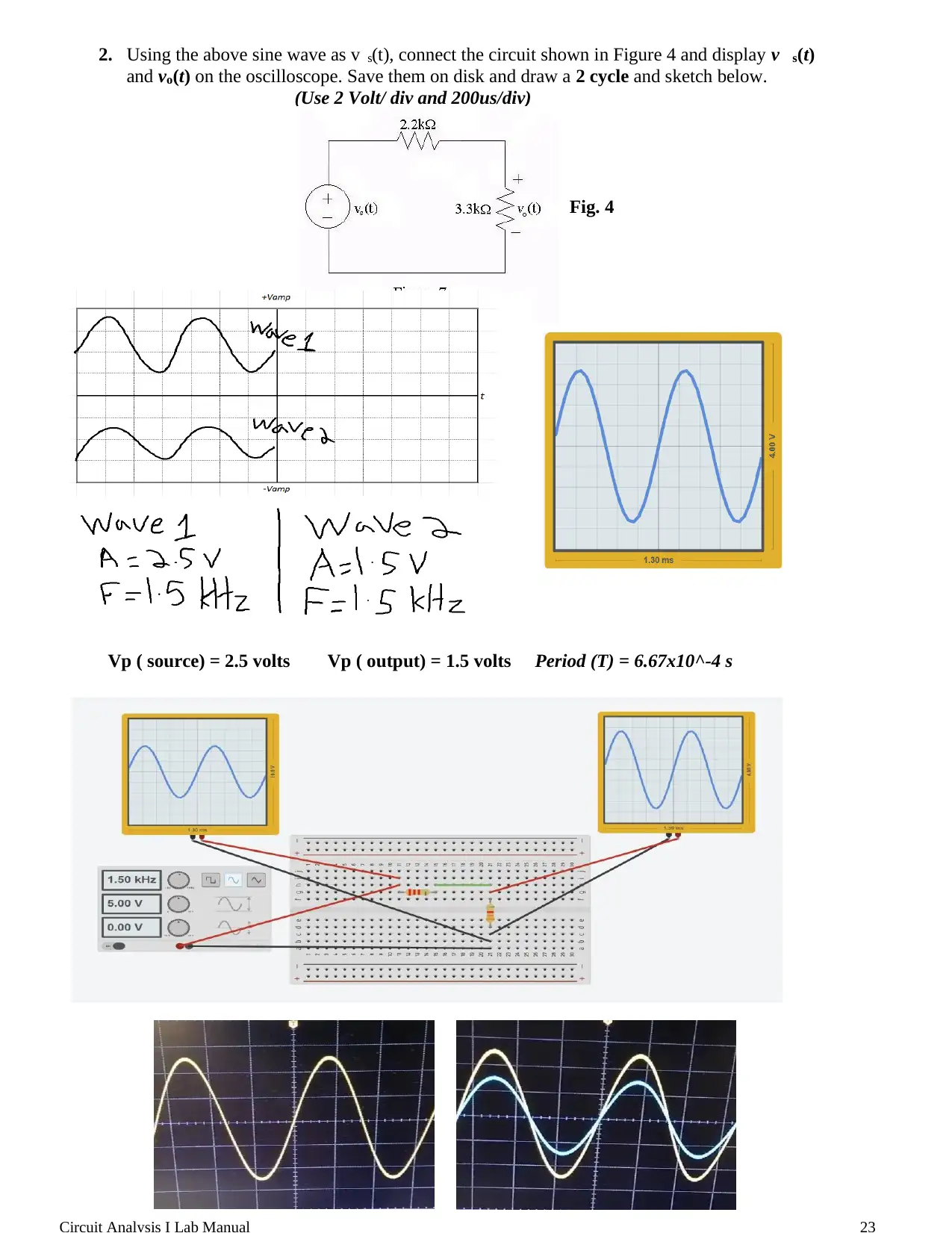
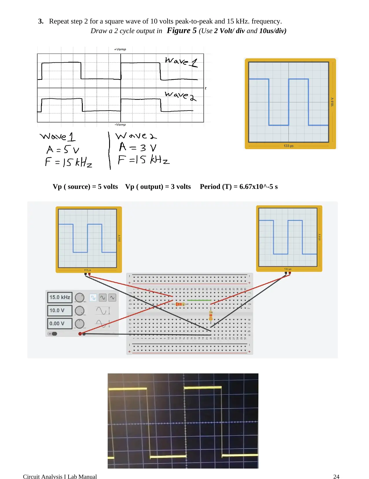
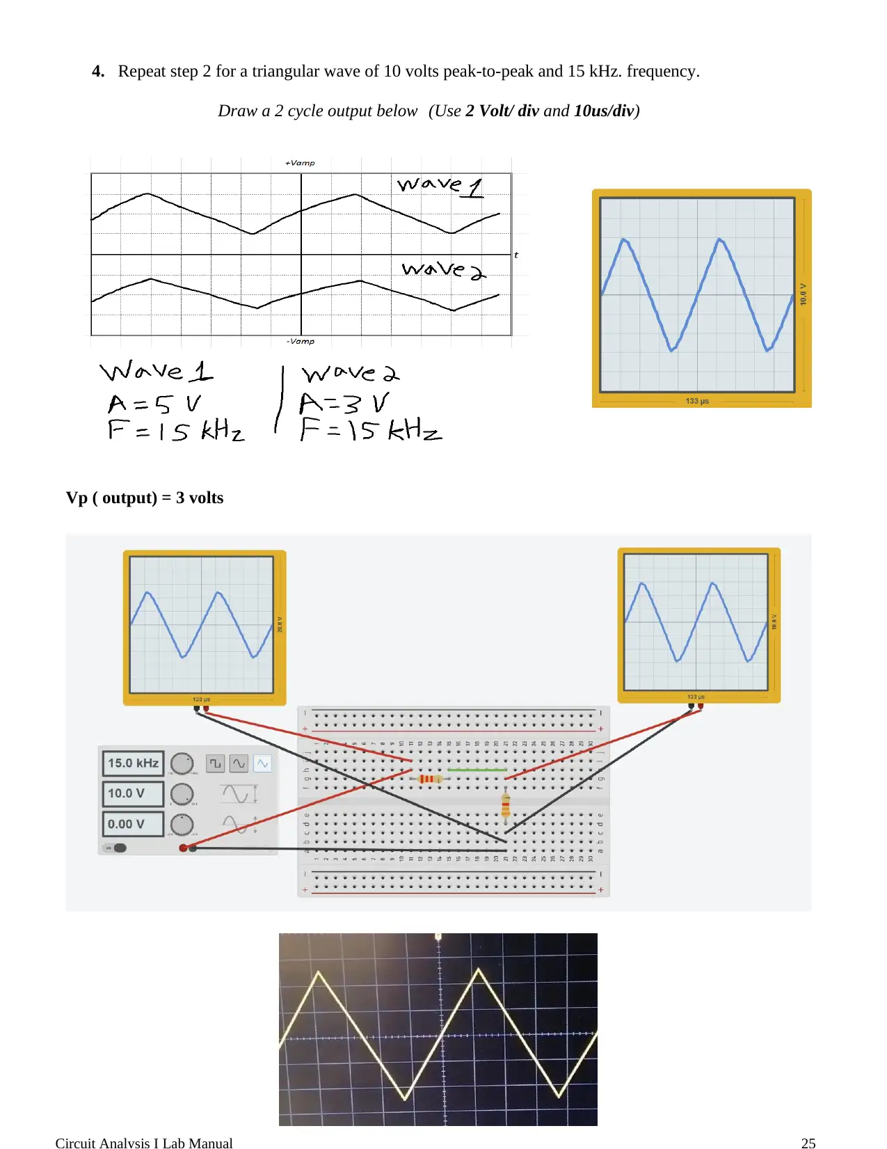
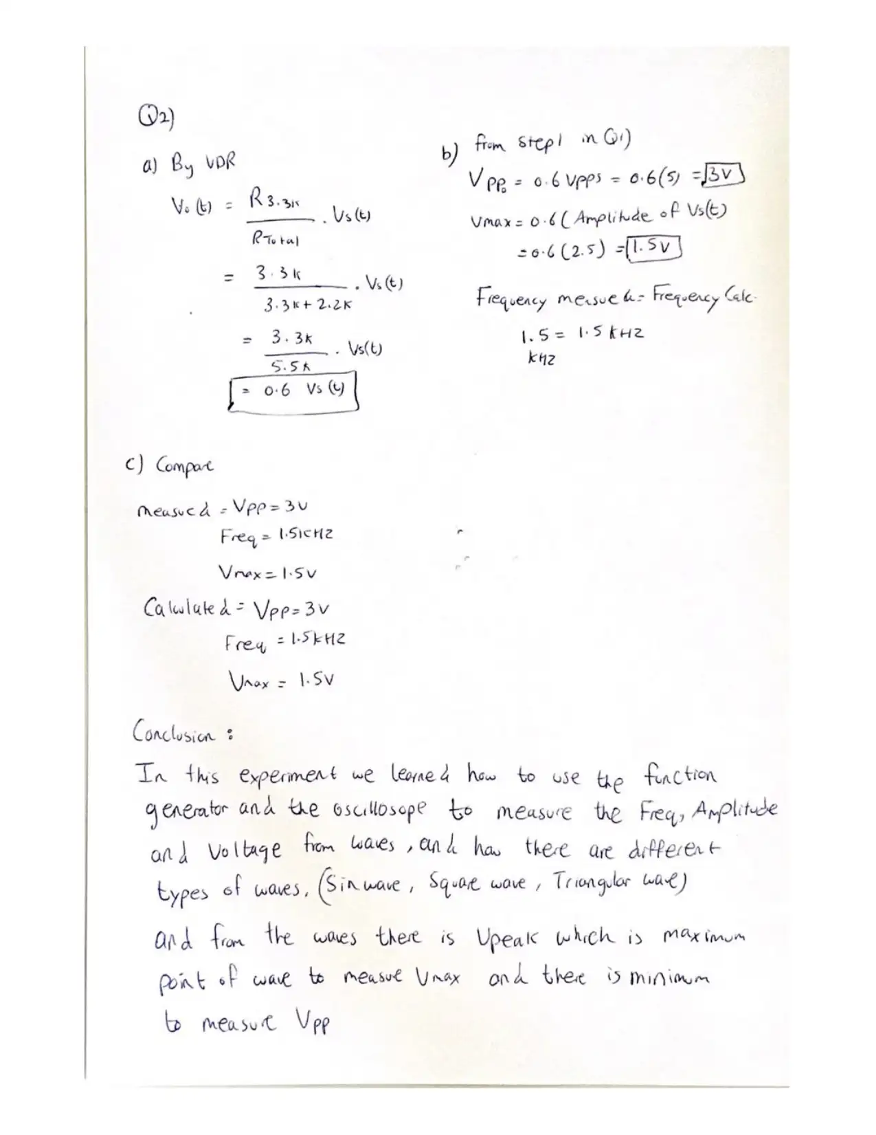
This document is a lab report from the Circuit Analysis I course at the University of Sharjah, focusing on an experiment involving a function generator and an oscilloscope. The objective of the lab was to learn the fundamentals of using a function generator to produce various waveforms (sine, square, and triangle) with controlled amplitude and frequency, and to use an oscilloscope to visualize and analyze these waveforms. The procedure involved generating sine, square, and triangular waves, measuring their characteristics (peak-to-peak voltage, frequency, and period), and observing the output of a simple circuit with a voltage divider. The results section includes plots of the recorded waveforms and a comparison of calculated and measured output voltages to demonstrate the applicability of the voltage divider rule for time-varying voltages. The report also includes a glossary of key terms related to waveforms and signal analysis.
1 out of 9
Related Documents


Your All-in-One AI-Powered Toolkit for Academic Success.
+13062052269
info@desklib.com
Available 24*7 on WhatsApp / Email
![[object Object]](/_next/static/media/star-bottom.7253800d.svg)
Copyright © 2020–2026 A2Z Services. All Rights Reserved. Developed and managed by ZUCOL.