DC Motor Speed Control with DSP: Gannon University Project 2019
VerifiedAdded on 2023/04/21
|18
|1305
|97
Project
AI Summary
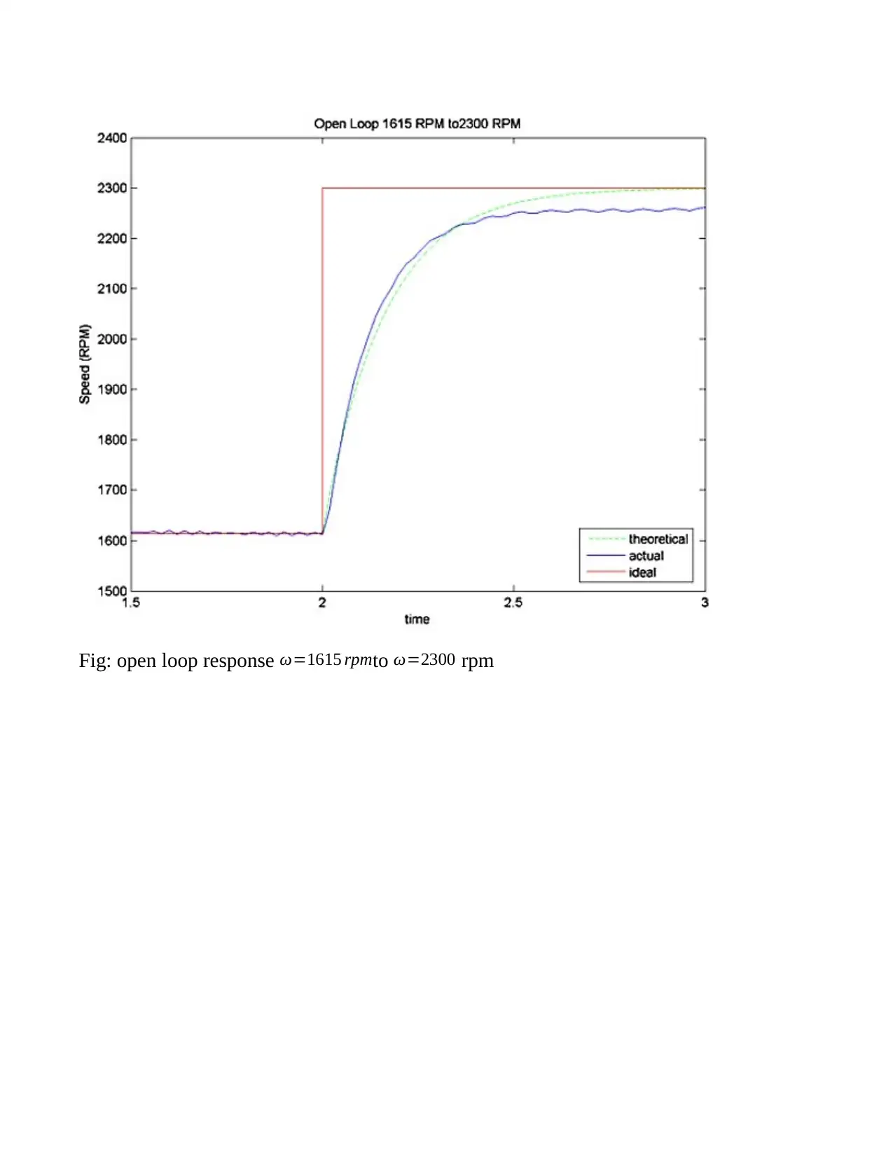
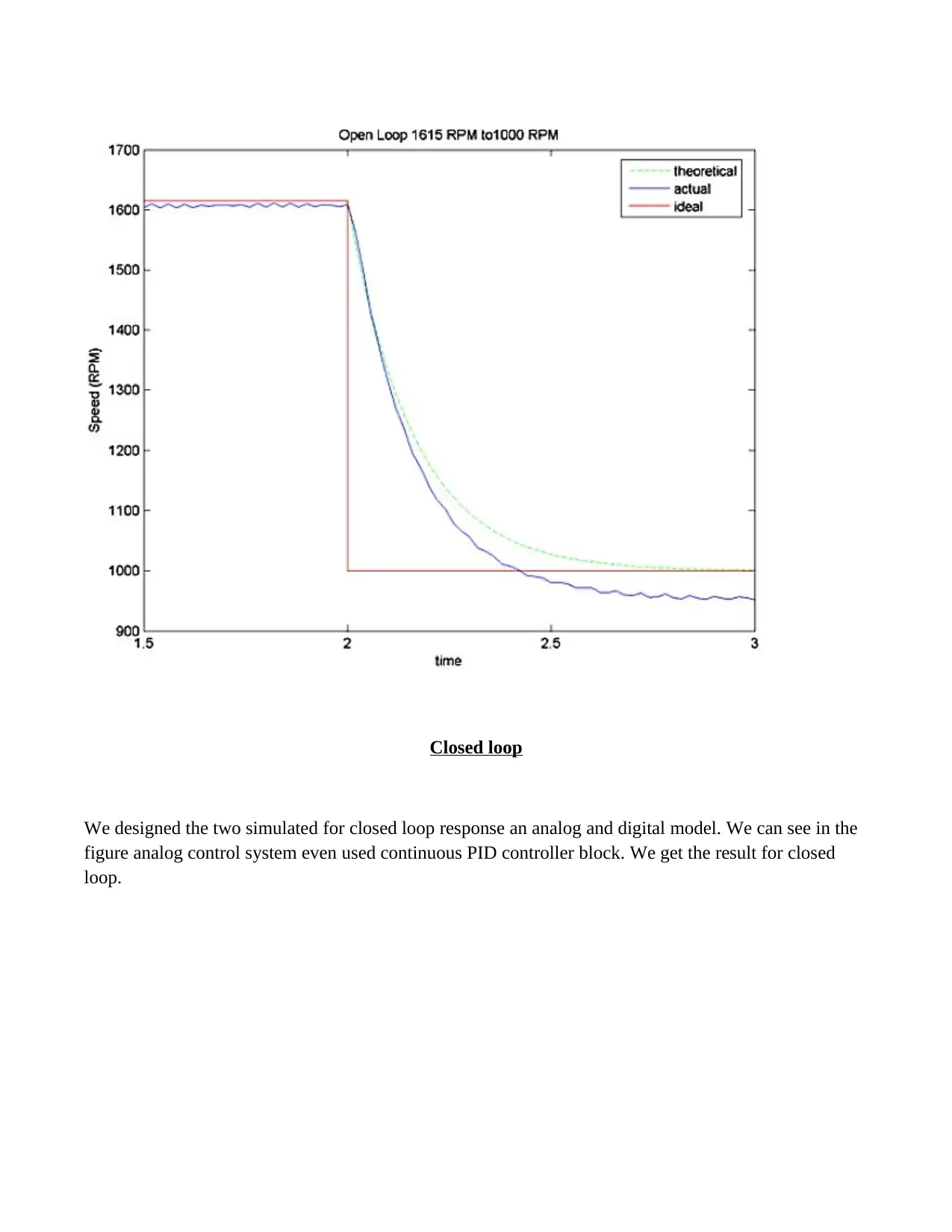
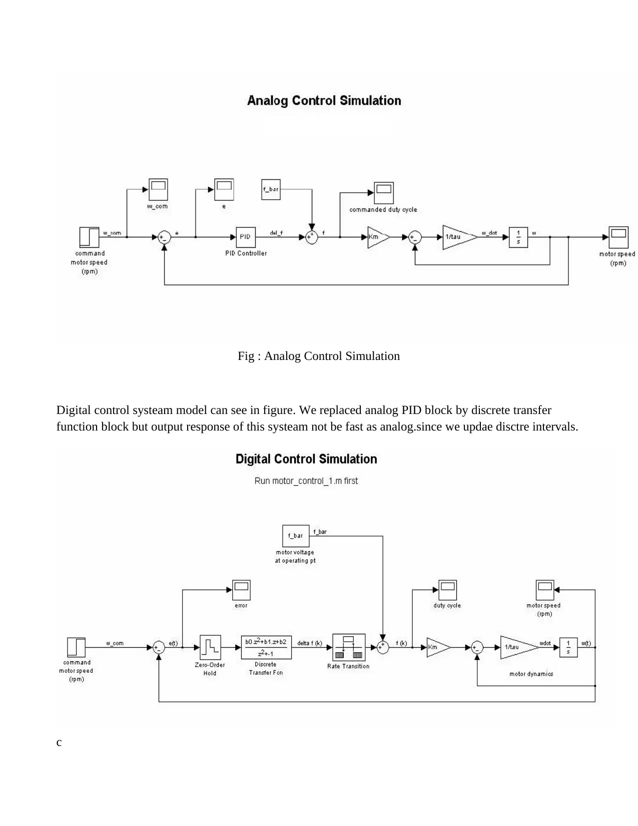
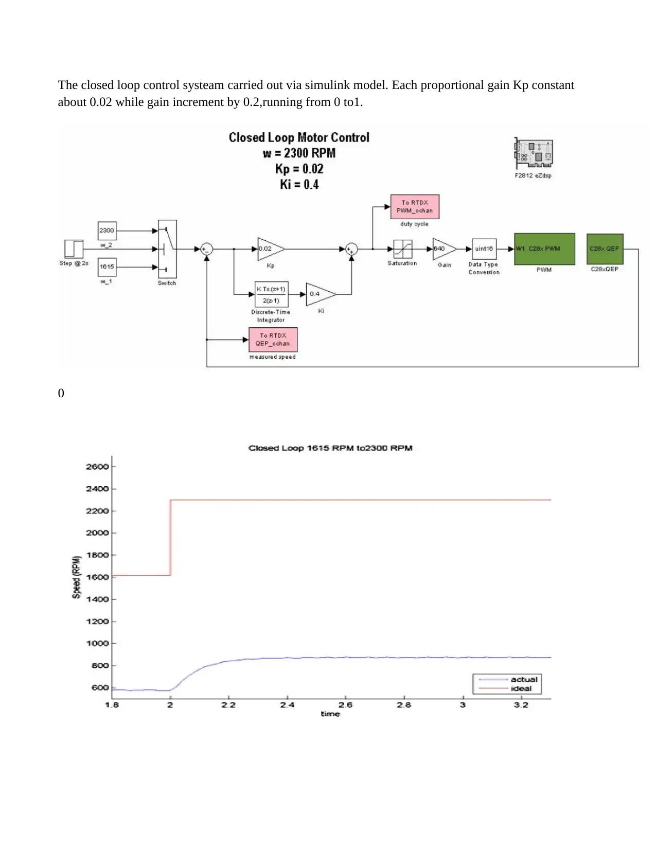
This engineering project, submitted to Gannon University, details the implementation of DC motor speed control using digital signal processing in MATLAB. It compares open-loop and closed-loop systems, applying command speed inputs and analyzing the motor's response. The project utilizes MATLAB and Simulink for system design and simulation, incorporating the Embedded Target for TI C2000 DSP for code generation and deployment. Open-loop control is evaluated with step changes in command speed, while closed-loop control is implemented using both analog and digital models. The results demonstrate the effectiveness of the designed control system, highlighting its quick response and minimal steady-state error. The project acknowledges the contributions of Sundaram Ramakrishna and other colleagues, emphasizing the importance of their guidance and expertise.
1 out of 18
Related Documents


Your All-in-One AI-Powered Toolkit for Academic Success.
+13062052269
info@desklib.com
Available 24*7 on WhatsApp / Email
![[object Object]](/_next/static/media/star-bottom.7253800d.svg)
Copyright © 2020–2026 A2Z Services. All Rights Reserved. Developed and managed by ZUCOL.