Automatic Identification of Welding Defects in Radiographic Images

Verified

Added on  2023/01/18

|8
|1851
|68
Report
AI Summary
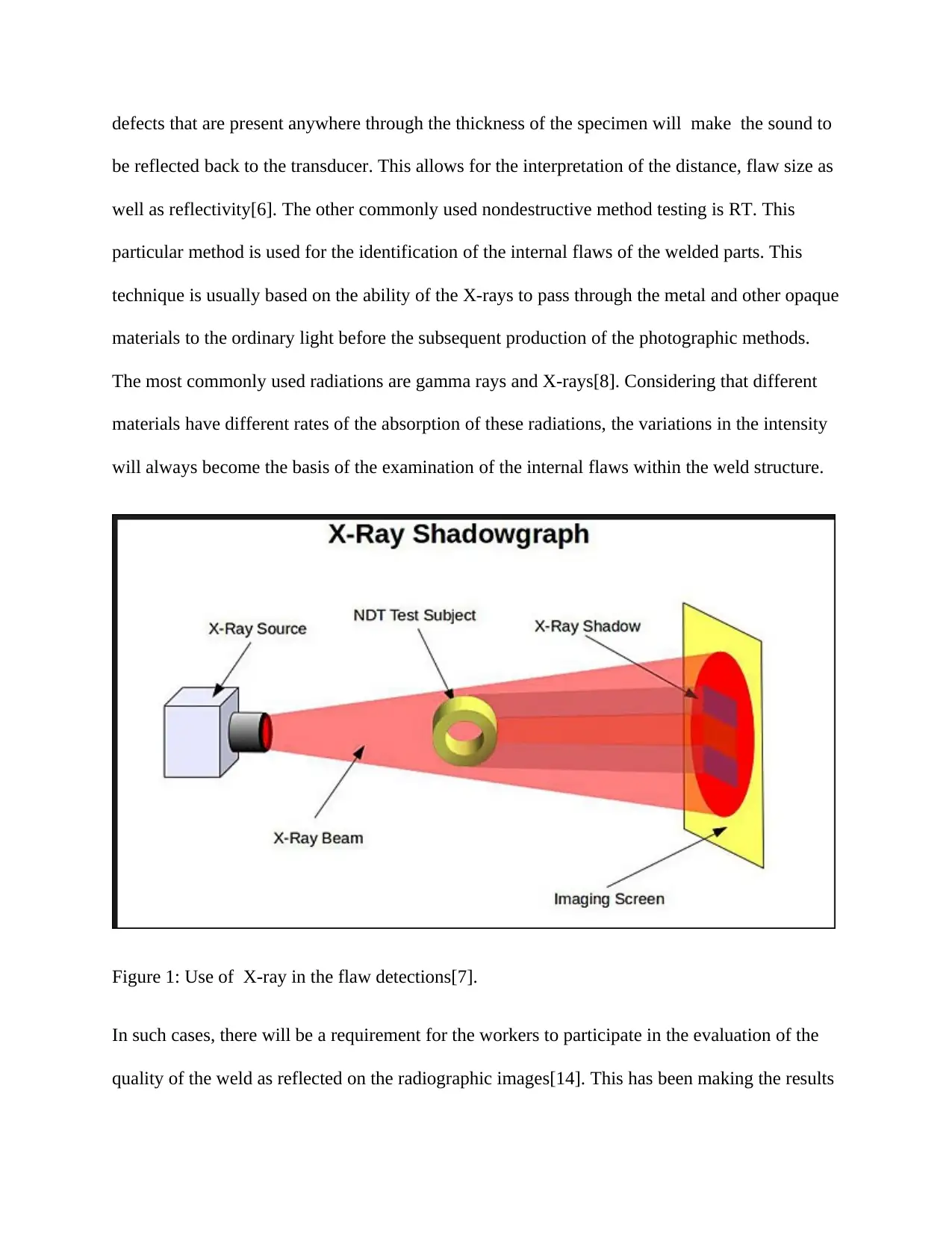
This report focuses on the automatic identification and classification of welding defects in radiographic images, a crucial aspect of ensuring the quality and safety of welded structures. The report begins by highlighting the importance of non-destructive testing (NDT) methods, such as radiographic testing (RT), in identifying internal flaws within welded components. It discusses the limitations of manual interpretation of radiographic images, which can be time-consuming, inconsistent, and subjective, and emphasizes the need for automated systems to improve consistency, objectivity, and efficiency. The report then reviews existing research efforts in this area, including weld segmentation, flawed segment identification, and defect classification. It points out the lack of commercially viable automated RT systems and outlines the key components of such a system: weld segmentation, flawed segment identification, and defect classification. The report also references various research papers and studies that have attempted to address the issue of automatic defect identification, including the use of image processing techniques, pattern recognition, and feature extraction. It concludes by presenting a system developed for the automatic identification and classification of welding defects in radiographic images, contributing to the ongoing research in this field.
Document Page
AUTOMATIC IDENTIFICATION OF DIFFERENT TYPES OF WELDING
DEFECTS IN RADIOGRAPHIC IMAGES
By Name
Course
Instructor
Institution
Location
Date
tabler-icon-diamond-filled.svg

Paraphrase This Document

Need a fresh take? Get an instant paraphrase of this document with our AI Paraphraser
Document Page
Inspection of the structures that have been welded is usually essential in ensuring that the quality
of weld are as per the requirements of the model used in designing as well as operations[1]. This
will assure the reliability and safety of the components. There are several non-destructive
methods available in the market that are being used in the inspection of the defects within the
welded components. The primary method of quality control programmes is visual inspections[2].
This method can be easily carried out and it is never expensive considering that it does not
require complex equipment apart from the magnifying lens, television camera systems or
boroscopes.
Such kind of the methods is preferred for use or evaluation of welded components where there is
a requirement of quick correction after detection of the flaws so as to save on the cost. For the
case of the critical welded structures including the high-pressure vessels the location, nature, and
magnitude of the flaws must be properly mapped in order to determine their acceptability by
other extra analysis methods[3]. In order to bring this kind of the situation to an end, more
complex non- destructive methods including the ultrasonic testing as well as the radiographic
testing are required. Both TR and UT methods have their limitations for example the defects on a
particular plain can be picked up on the specific material and not the other and the reverse is true.
These two techniques are usually known to complement each other and their application should
be concurrent where there are low prices[5].
The inspection involving ultrasonic uses the sound waves of very short wavelengths and high
frequency in the flaw detection. In most cases, a pulsed beam of high-frequency ultrasound is
used through a transducer that is put on the specimen. Any sound from the specific pulse that is
transmitted back to the transducer in the form an echo is reflected on the screen[4]. This will give
the amplitude of the generated pulse. The time taken for the wave to return is also recorded. The
Document Page
defects that are present anywhere through the thickness of the specimen will make the sound to
be reflected back to the transducer. This allows for the interpretation of the distance, flaw size as
well as reflectivity[6]. The other commonly used nondestructive method testing is RT. This
particular method is used for the identification of the internal flaws of the welded parts. This
technique is usually based on the ability of the X-rays to pass through the metal and other opaque
materials to the ordinary light before the subsequent production of the photographic methods.
The most commonly used radiations are gamma rays and X-rays[8]. Considering that different
materials have different rates of the absorption of these radiations, the variations in the intensity
will always become the basis of the examination of the internal flaws within the weld structure.
Figure 1: Use of X-ray in the flaw detections[7].
In such cases, there will be a requirement for the workers to participate in the evaluation of the
quality of the weld as reflected on the radiographic images[14]. This has been making the results
Document Page
to vary significantly depending on the competence and the operator’s experience. The process of
doing interpretation manually takes a lot of time and the result obtained appears to be
inconsistent, subjective and usually biased [9]. It is therefore desirable to come up with a system
that will increase the consistency, objectivity, and efficiency of the RT inspections. As far as this
particular research work is concerned, there are no commercially viable automated systems of
RT which are in existence today. This is because, as per the scientific requirement, an automated
system of RT can be functionally grouped into three: Weld segmentation from the background,
flawed segment identification and finally classification of the different types of the flaws. Such
kind of developments is known to rely primarily on the image processes using techniques,
pattern recognition, and feature extraction[10].
The information available from the literature sources points out some of the crucial attempts that
have been made by the scholars to address this particular issue. Ni and Liao proposed a
mechanism of the weld extraction from the images of digitized radiographic[11]. This particular
method has been based on the observation on the pixel intensities in the area of the weld which
are found to be more as compared to other parts of the images[13]. This particular method
proved to be effective in the segmentation of the linear welds only. There was the subsequent
application of the multi-layer perceptron of the neuron network commonly known MLP by the
use of the same procedure[12].
The method became successful for the case of the linear welds as well as the curved surfaces.
After the successful extraction of the weld, there was an interest to note the defective areas in the
weld. The proposed algorithm for segmentation by some of the researchers proved to be effective
other than considering the type of the defect. The process involved four distinct stages including
curve fitting, preprocessing, post-processing and finally profile anomaly detection. The results
tabler-icon-diamond-filled.svg

Paraphrase This Document

Need a fresh take? Get an instant paraphrase of this document with our AI Paraphraser
Document Page
indicated that the method was successful in higher rate identification. This identification was
however not automatic [15].
However, there is not much research done on the automatic identification of the type of defects
on the welds in radiographic images. Some researchers have done the classification of the types
of defects with a system of experts. The expert system involves the use of the feature such as the
intensity level of the defect pattern, shape and final position. The results that are obtained from
this particular method purely depend on the defect types[7]. While using the system of experts, it
is easy to detect the blow holes but the detection of the cracks is very difficult. In some cases, the
identification of the flaws has been done based on the interviews with inspectors who are the
experts. In this method, there has been the extraction of at least three features including location,
intensity, and shape. Such results have still not been considered satisfactory[16]. This particular
paper presents a system that has been developed for the automatic identification and
classification of the welding defects in radiographic images as a contribution to the ongoing
research on the subject matter..
Document Page
References
[1] D.W.Cho,W.H., Song, W.H., Cho and S.J Na.,. Analysis of the submerged arc welding
process by three-dimensional computational fluid dynamics simulations. Journal of Materials
Processing Technology, 2013; 213(12), pp.2278-2291.
[2] B.Fu, G. Qin, F. Li, X., Meng J., Zhang, and Wu,,. Friction stir welding process of dissimilar
metals of 6061-T6 aluminum alloy to AZ31B magnesium alloy. Journal of Materials Processing
Technology, 2015;218, pp.38-47.
[3] V.S.Gadakh V.B. Shinde, N.S and Khemnar Optimization of welding process parameters
using MOORA method. The International Journal of Advanced Manufacturing Technology, ,
2013;69(9-12), pp.2031-2039.
[4] B.T.Gibson,.D.H. Lammlein, T.J, Prater, W.R., Longhurst, C.D. Cox, M.C. Ball, K.J.
DharmarajG.E, Cook, . and A.M .Strauss, . Friction stir welding: Process, automation, and
control. Journal of Manufacturing Processes, 2014; 16(1), pp.56-73.
[5] E. Hillen, J Daniel, T. Matthews, and S. Peters,., Lincoln Global Inc,. System and method for
controlling a hybrid welding process. U.S. Patent 2015; 8,952,291.
[6] M.Islam, A. Buijk, M. Rais-Rohani, and K. Motoyama,. Simulation-based numerical
optimization of the arc welding process for reduced distortion in welded structures. Finite
Elements in Analysis and Design, 2014; 84, pp.54-64.
[7] S. Kanemaru T. Sasaki, T Sato, H Mishima, S, Tashiro, M and Tanaka, Study for TIG–MIG
hybrid welding process. Welding in the World, 2014; 58(1), pp.11-18.
Document Page
[8] J.Kreindl, and S.Glanseck, H. Fronius International Gmb,. Device and method for simulating
a welding process. U.S. Patent 2014;8,777,629.
[9] Y.Lu, S. Chen, Y Shi, X. Li, J, Chen, L. Kvidahl, Y and Y. Zhang. Double-electrode arc
welding process: principle, variants, control, and developments. Journal of Manufacturing
Processes, 2014;16(1), pp.93-108.
[10] J.Mazumder and S.H. Lee, University of MichiganMonitoring of a welding process. U.S.
Patent 8, , 2014. ;723,078.
[11] D.M. Neto and P.Neto. Numerical modeling of friction stir welding process: a literature
review. The International Journal of Advanced Manufacturing Technology, 2013;65(1-4),
pp.115-126.
[12] K.Panneerselvam and K. Lenin,. Joining of Nylon 6 plate by friction stir welding process
using a threaded pin profile. 2014;Materials & Design, 53, pp.302-307.
[13] B.Sardy, G.and Trauner,H. Fronius International Gmb, A welding method for carrying out a
welding process. U.S. Patent 2013.;8,389,897.
[14] W.Tan, Y.C.and Shin. Multi-scale modeling of solidification and microstructure
development in laser keyhole welding process for austenitic stainless steel. Computational
Materials Science, , 2015;98, pp.446-458.
[15] C.S Wu,L. Wang, W.J. Ren and X.Y. Zhang ;. Plasma arc welding: Process, sensing,
control, and modeling. Journal of manufacturing processes, 2014;16(1), pp.74-85.
tabler-icon-diamond-filled.svg

Paraphrase This Document

Need a fresh take? Get an instant paraphrase of this document with our AI Paraphraser
Document Page
[16] D.You, X. Gao and S. Katayama,. WPD-PCA-based laser welding process monitoring and
defects diagnosis by using FNN and SVM. IEEE Transactions on Industrial Electronics, 2015;
62(1), pp.628-636.
chevron_up_icon
1 out of 8
circle_padding
hide_on_mobile
zoom_out_icon
[object Object]